|
|
|
Porsche, and the Porsche crest are registered trademarks of Dr. Ing. h.c. F. Porsche AG.
This site is not affiliated with Porsche in any way. Its only purpose is to provide an online forum for car enthusiasts. All other trademarks are property of their respective owners. |
|
|


| byndbad914 |
 Oct 2 2006, 03:55 PM Oct 2 2006, 03:55 PM
Post
#1
|
|
shoehorn and some butter - it fits  Group: Members Posts: 1,547 Joined: 23-January 06 From: Broomfield, CO Member No.: 5,463 Region Association: None |
So, freakin' German cars. Really, I have little to say for "German Engineering". So, I am rewiring the car from scratch (more or less - using old harness as a guide) and upgrading to the "correct" way to fuse a circuit with a Painless Fuse block. Anyway, it is easy to just run new wires to the item being switched on and fuse the hot wire to the switch = say headlights for instance... I fuse the hot in, then "splice" the wires that were at the original fuse panel (not splicing, running all new wire, but that helps paint the picture hopefully).
Then I get to the hazard light switch. There is about 15 wires off of that one switch! I can figure out the stuff for the most part - EXCEPT FOR HOW THEY ARE RELAYING THE FLASHER. I can't tell if they are intermittently breaking power (12V switched) or intermittently breaking the ground. And the design seems to have this crazy kind of 12V looping going on (tho' won't go into that). Anyway, I need to easily pull that relay outta the system (as the new fuse panel has the 12V signal intermittent relayed) but am worried about how the grounding works. So, that paints the picture (hopefully), here is a straight-forward series of questions: 1. There is a black with green stripe and white swirl wire that is split - one goes from the switch to the steering column and the other from the switch to that freakin' relay. Does this carry 12V constant?? (I am assuming it is constant 12V to make the turn signals work by passing 12V from that wire to either the blk/wht or blk/green return to flash the lights.) a. If the wire inquestion is in fact 12V hot thru the switch, then I can figure the rest out from there. If not, if it somehow gets an intermittent 12V supplied from that funky relay, please let me know and I can work with that too. If it doesn't match anything above, then I will probably just take a hammer to the switch altogether, swear in the few German words I know, and just wire in my own switch. But I really want to keep the stock looking switch on the dash. Worst case I pull out the DMM tonight and swear under my breath while I figure that switch out, but any help is very appreciated. I have spent HOURS yesterday and was up 'til 3AM (no shit!!) reading thru the wire diagrams trying to figure out that relay and overall loop. And I can wire a car no problem... so this is just un-freakin-buleavabul. |
   |

 
|
  |
Replies
| jk76.914 |
Oct 2 2006, 04:52 PM
Post
#2
|
|
Senior Member Group: Members Posts: 809 Joined: 12-April 05 From: Massachusetts Member No.: 3,925 Region Association: North East States |
Take a look at this thread. I spend a long time figuring this out a couple of months ago-
http://www.914world.com/bbs2/index.php?show...c=47236&hl= Basically, the flasher relay connects to +12v, and then ANYTHING that needs to blink is connected to the flasher's output, and turned on by grounding that specific item. Turn signals get weird, though, because the circuit is designed to cause BOTH indicators to blink if an exterior bulb burns out. That's what is explained in the thread...... Understand how the flasher works, and you'll figure out the rest. I did, and I'm not that bright. (for proof of that- I put an hydraulic cam in my 914! (IMG:style_emoticons/default/wacko.gif) ) GOOD LUCK!! Jim |
|
|
|
| byndbad914 |
Oct 2 2006, 05:23 PM
Post
#3
|
|
shoehorn and some butter - it fits Group: Members Posts: 1,547 Joined: 23-January 06 From: Broomfield, CO Member No.: 5,463 Region Association: None |
QUOTE(jk76.914 @ Oct 2 2006, 03:52 PM)  Basically, the flasher relay connects to +12v, and then ANYTHING that needs to blink is connected to the flasher's output, and turned on by grounding that specific item. So I looked at your post (thanks btw) and saw your diagram below. 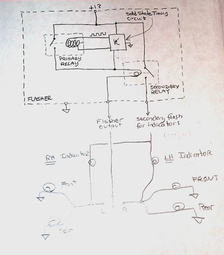 So, to verify, you have a 12V supplied wire (red wire, hot all the time), a ground wire (the brown one of course), then... 1. the black/grn/wht swirl has an intermittent 12V supplied by the relay? This makes sense to me... but do you agree it is intermittent 12V supplied back to the switch? 2. the blue/wht wire also has an intermittent 12V supplied by the relay?? This makes absolutely no sense to me and is the "circular thing" I mentioned earlier. Circular in that the indicator light has only two wires connected to it - either a blk/wht or blk/grn depending on L or R. THOSE WIRES WILL ALSO HAVE an intermittent 12V SUPPLIED TO THEM, right??? So that means the indicator light doesn't seem to have a ground, just 12v hitting it from both sides. The only ground I can figure out in that setup is at the flashing bulb. But current flow is the wrong direction and I can't see how that can work - I mean, it does apparently work but must be in a manner I don't understand. This is very typical German engineering - just do the craziest, over-thought thing you can and produce it v. a very simple setup. It is like they went to meetings and if the guy presenting couldn't explain the circuit clearly, but it worked, then they picked that one (IMG:style_emoticons/default/dry.gif) QUOTE Understand how the flasher works, and you'll figure out the rest. GOOD LUCK!! Jim for sure this is the hardest part of the system! Everything else I already have a plan for (tho' hard to say if it will all work (IMG:style_emoticons/default/biggrin.gif) ) |
|
|
|
Posts in this topic
 byndbad914 electrical gurus - how does the f'ing turn signal "loop" Oct 2 2006, 03:55 PM
 byndbad914 Further explanation of my confusion:
I think that... Oct 2 2006, 04:33 PM
byndbad914 Further explanation of my confusion:
I think that... Oct 2 2006, 04:33 PM
 byndbad914
 |
1 User(s) are reading this topic (1 Guests and 0 Anonymous Users)
0 Members:

|
Lo-Fi Version | Time is now: 4th July 2025 - 12:28 AM |
Invision Power Board
v9.1.4 © 2025 IPS, Inc.
| All rights reserved 914World.com © since 2002 |
|
914World.com is the fastest growing online 914 community! We have it all, classifieds, events, forums, vendors, parts, autocross, racing, technical articles, events calendar, newsletter, restoration, gallery, archives, history and more for your Porsche 914 ... |