|
|
|
Porsche, and the Porsche crest are registered trademarks of Dr. Ing. h.c. F. Porsche AG.
This site is not affiliated with Porsche in any way. Its only purpose is to provide an online forum for car enthusiasts. All other trademarks are property of their respective owners. |
|
|


| worn |
 Sep 9 2013, 09:33 AM Sep 9 2013, 09:33 AM
Post
#1
|
|
can't remember  Group: Members Posts: 3,162 Joined: 3-June 11 From: Madison, WI Member No.: 13,152 Region Association: Upper MidWest |
I thought I would show a few pics of the tool set I made to overcome the MPS tuning. Note I started with an inductance gauge and vacuum line to make graphs of the changes induced by vacuum. This served as baseline out of the car. Then when the car was running I used these with the MPS in place:
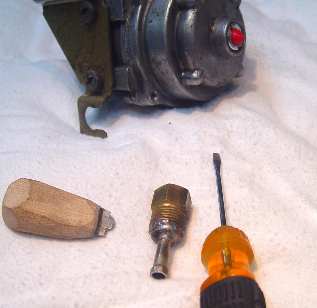 The kit has three pieces, plus an MPS mod through the cap (red plug). First there is a small screw driver for the main adjustment screw that alters rich vs lean. Second is a 7 mm nut ground to fit ito the hex of the aluminum diaphragm adjuster stop. The nut is soldered to a tube and a plumbing piece as a handle (I used stainless steel braze -orange$). The nut is drilled out to allow the screw driver access to the screw. Finally a scrap of 18 ga steel in a wood handle for the cap screw that adjusts where WOT ends up. There is a red plug in the aluminum cap. The cap has been drilled as can be seen here: 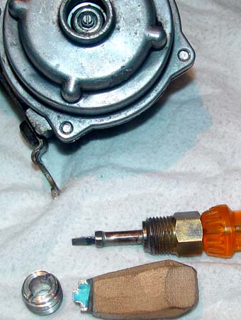 The shoulder is still on the plug, and in this MPS the hole does not make an air leak. It would be air tight with the simpler versions on Ca '69 type 3 and 4 models. Here is a shot showing the hex end and the screw inside it. Sort of like valve adjusters. 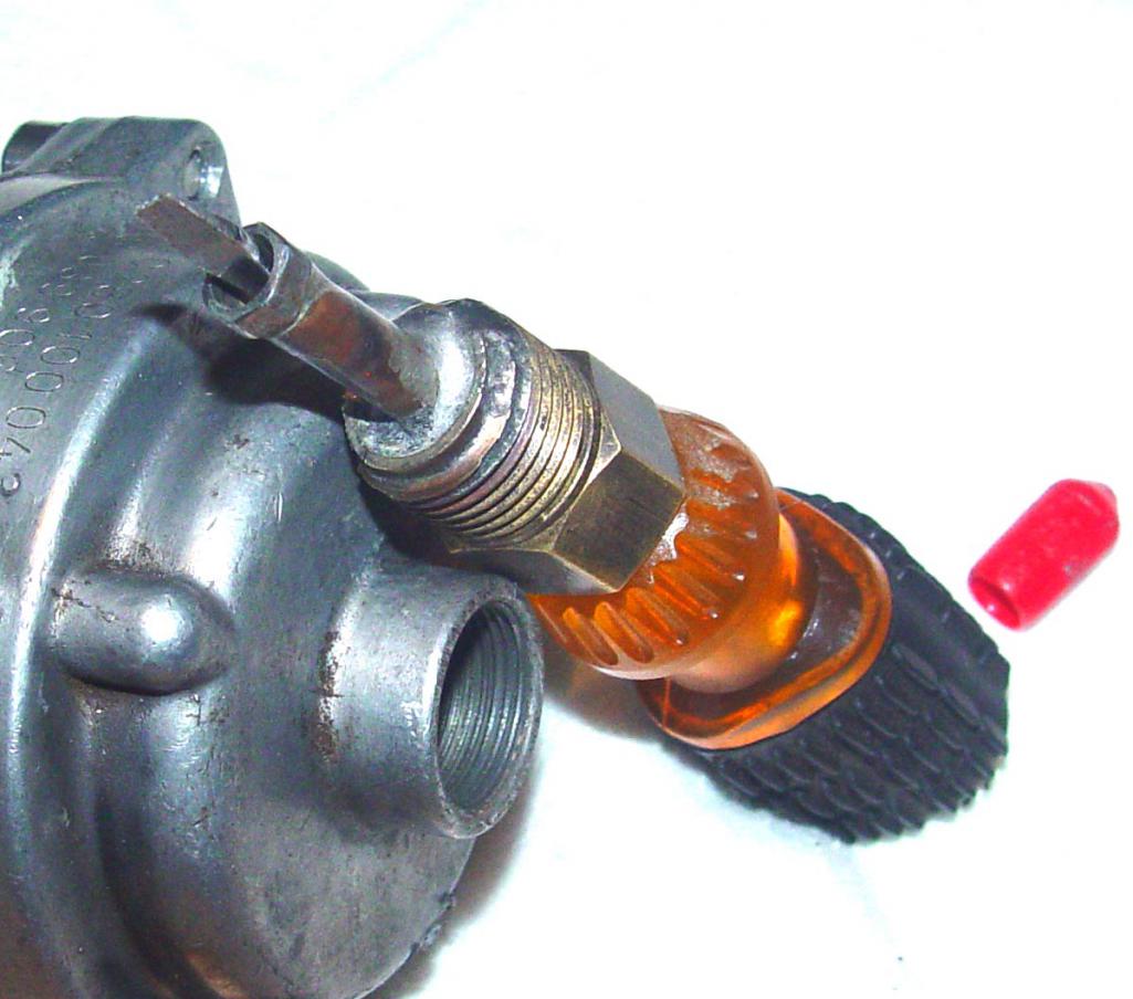 And here we go. Normally this would be a hot engine bay. It is important to have all three screws right, but I used the outer plug and the inner screw had the most impact. I found it very helpful to be able to make adjustments without disturbing the outer stop, so I needed to have a hole through it so any of the three screws can be moved without moving one of the others, and also in short increments as you pull over and try to find the right setting. You want to seat the hex first and then find the slot for the screw driver. I tried to make it so I could turn the small screw while holding the aluminum one still. I just bought a non-working type 3/4 on ebay without the secondary diaphragm that Racer Chris sells (thanks!). It can be fixed and I will give it a try. 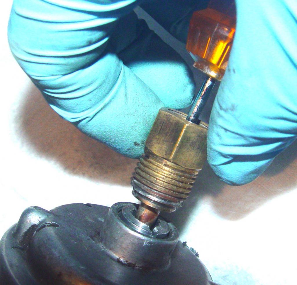 |
   |

 
|
Posts in this topic
 worn tools for the MPS Sep 9 2013, 09:33 AM
 Java2570 Please do post about the Type 3/4 MPS...I've g... Sep 9 2013, 09:49 AM
 worn
Please do post about the Type 3/4 MPS...I've ... Sep 9 2013, 10:22 AM worn
[quote name='Java2570' post='1923235' date='Sep 9... Sep 9 2013, 09:32 PM Jeff Bowlsby Creative! But why not just get the MPS tools... Sep 9 2013, 12:41 PM worn
Creative! But why not just get the MPS tool... Sep 9 2013, 12:55 PM Jeff Bowlsby Thats cool...you did it beacsue you could...[appla... Sep 9 2013, 01:32 PM worn
Ah, but that big hole in the WOT stop will be ha... Sep 9 2013, 01:58 PM Jeff Bowlsby
Ah, but that big hole in the WOT stop will be h... Sep 9 2013, 02:09 PM DBCooper You graphed the curves? Then wouldn't it be a... Sep 10 2013, 08:54 AM worn
You graphed the curves? Then wouldn't it be ... Sep 10 2013, 12:25 PM DBCooper I don't have an MPS so this isn't a concer... Sep 10 2013, 09:03 PM
worn
Please do post about the Type 3/4 MPS...I've ... Sep 9 2013, 10:22 AM worn
[quote name='Java2570' post='1923235' date='Sep 9... Sep 9 2013, 09:32 PM Jeff Bowlsby Creative! But why not just get the MPS tools... Sep 9 2013, 12:41 PM worn
Creative! But why not just get the MPS tool... Sep 9 2013, 12:55 PM Jeff Bowlsby Thats cool...you did it beacsue you could...[appla... Sep 9 2013, 01:32 PM worn
Ah, but that big hole in the WOT stop will be ha... Sep 9 2013, 01:58 PM Jeff Bowlsby
Ah, but that big hole in the WOT stop will be h... Sep 9 2013, 02:09 PM DBCooper You graphed the curves? Then wouldn't it be a... Sep 10 2013, 08:54 AM worn
You graphed the curves? Then wouldn't it be ... Sep 10 2013, 12:25 PM DBCooper I don't have an MPS so this isn't a concer... Sep 10 2013, 09:03 PM  |
1 User(s) are reading this topic (1 Guests and 0 Anonymous Users)
0 Members:

|
Lo-Fi Version | Time is now: 7th June 2024 - 01:23 PM |
Invision Power Board
v9.1.4 © 2024 IPS, Inc.