|
|
|
Porsche, and the Porsche crest are registered trademarks of Dr. Ing. h.c. F. Porsche AG.
This site is not affiliated with Porsche in any way. Its only purpose is to provide an online forum for car enthusiasts. All other trademarks are property of their respective owners. |
|
|


| BillC |
 Jan 15 2017, 05:07 PM Jan 15 2017, 05:07 PM
Post
#1
|
|
Senior Member  Group: Members Posts: 544 Joined: 24-April 15 From: Silver Spring, MD Member No.: 18,667 Region Association: MidAtlantic Region |
3-port Fuel Pump Necropsy (i.e., what's in there?)
Thanks to the generosity of a well-known, well-respected forum member, I ended up with a no-cost non-functioning 3-port fuel pump. Well, it did run, but it leaked out the electrical plug (same as my original pump). Since I figured that I probably wasn’t the only one curious about what’s inside one of these pumps, I decided to take pictures while disassembling it to see what’s in there. Figure 1 shows the “volunteer”. Figure 1: Fuel Pump 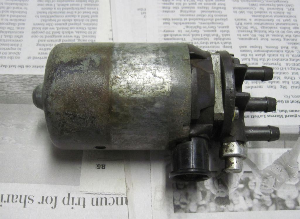 Figure 2: Fuel Pump ports 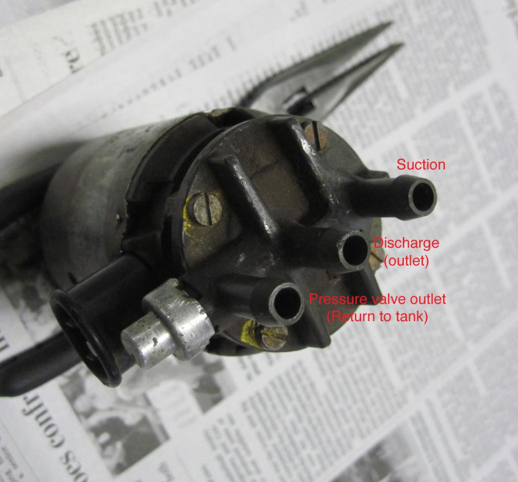 Figures 1 and 2 shows the three ports on the fuel pump. The top port is the suction, or inlet, port. The middle port is the discharge, or outlet, port. And the bottom port is the outlet from the pressure control valve. This port is normally tee’d into the return from the fuel injectors, and goes back to the fuel tank. The first step in our necropsy is to remove the cover with the ports and the check/pressure valve. The four screws shown in Figure 2 are removed and the plate pops off. See Figure 3 for the inside of the pump body. Figure 3: Inside of pump body 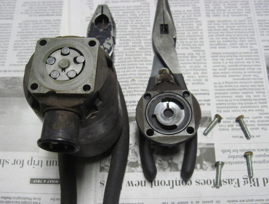 As can be seen, the pump is a rotary vane type pump, using steel rollers instead of sliding vanes. Figures 4 and 5 show the pump and its parts in more detail. Figure 4: Pump close up 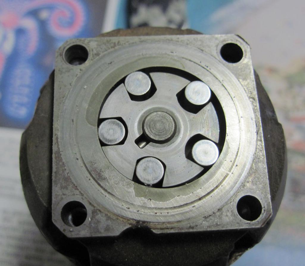 Figure 5: Pump parts 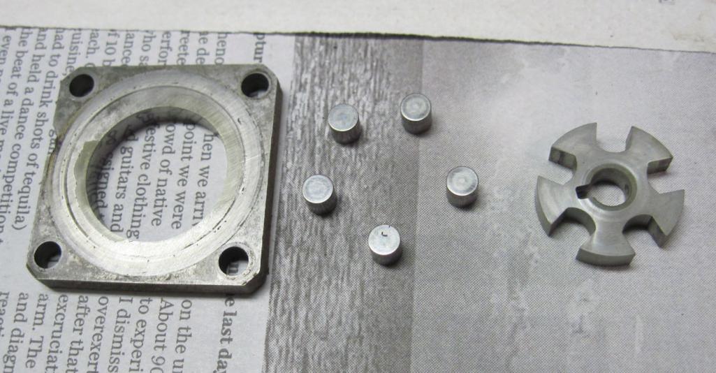 Figure 6: Pump face on pump body 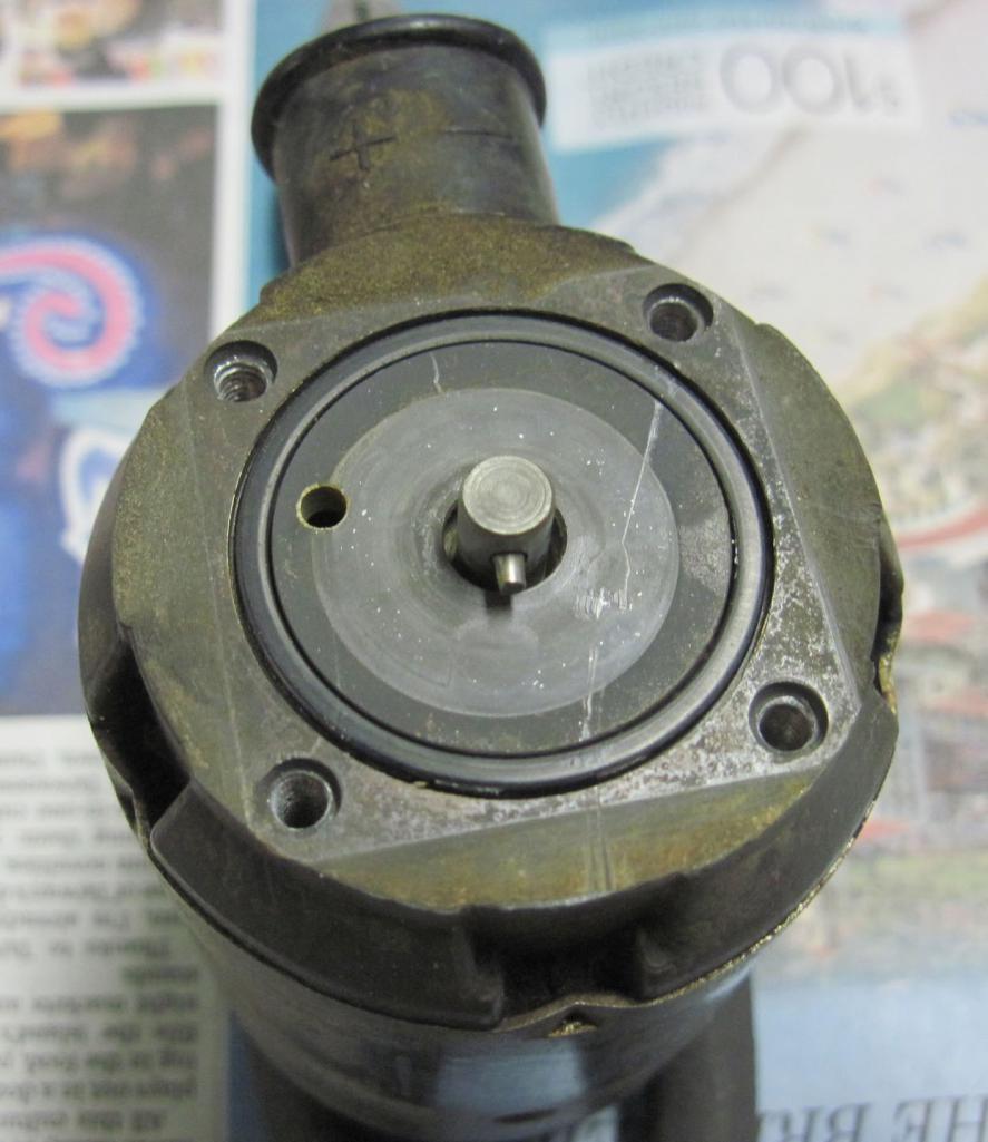 Figure 6 shows the face of the pump on the pump body. Note the small hole in the face near the rotor shaft, at approximately 9:30 – this hole lets fuel into the electric motor housing (in addition to that which seeps through the front bushing). Also note the “+” and “-“ markings on the electrical connector at the top of the picture. These electrical polarity markings are important, since the negative pole is actually grounded to the motor case (will show in more detail later). Returning to the pump cover, the next step is to remove the aluminum cap retaining the check/pressure valve parts. This valve performs two functions – it acts as a check valve on the discharge port, holding pressure when the pump is off; and it also as a pressure control valve, opening the return port whenever internal pressure is too high. Figure 7: Valve parts 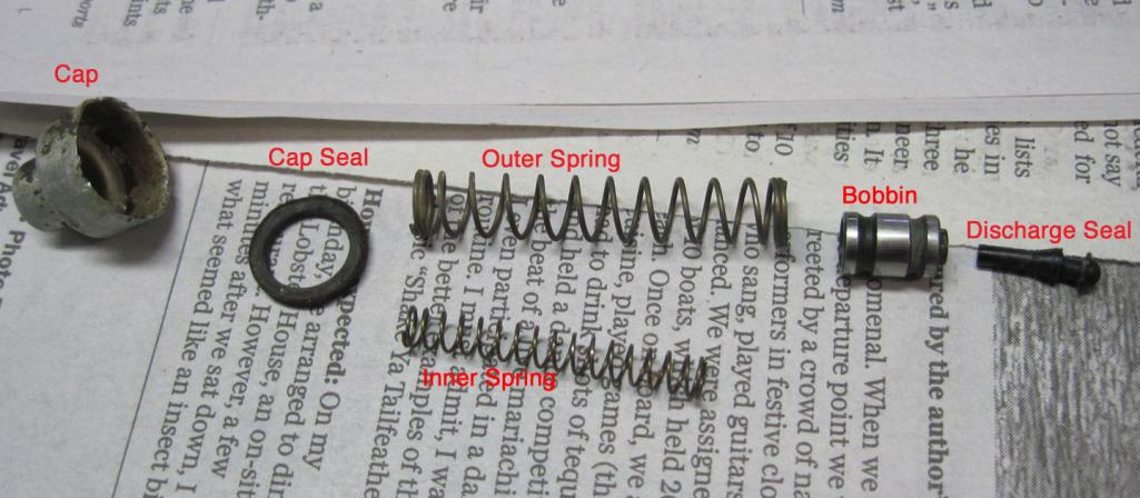 As can be seen in Figure 7, the valve consists of a discharge seal, a valve bobbin, two springs, a cap seal and the cap. The discharge seal actually fits inside the bobbin and seals the discharge port when pressure inside the pump drops. The two springs are installed coaxially, with the inner spring extending inside the bobbin and the outer spring on the backside of the bobbin. The seal looks like an o-ring, but is pressed down when the cap is crimped onto the pump cover. Figure 8 shows a close-up of the check valve seat, down the valve body hole in the cover. Figure 8: Detail of check valve seat 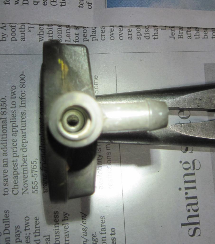 Now it is time to disassemble the motor body. This is actually the most difficult part disassembly, since there are 5 crimps along the perimeter of the motor canister, retaining the pump face. The crimps can be seen in Figures 1 and 2. If you decide to disassemble a pump motor, be very careful when removing the crimps – it is easy to slip and injure yourself (ask me how I know….). Figure 9: Inside the motor can 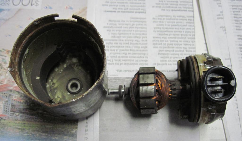 Figure 9 shows the parts internals of the motor can. On the left of the picture, you can see the rear rotor bushing and the two magnets inside the can. On the right, you can see the rotor and the brush plate assembly. Figure 10: Back side of pump face 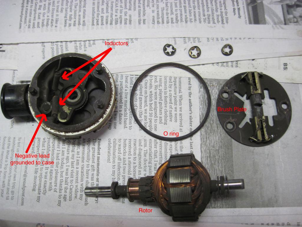 Figure 10 shows the parts on the back side of the pump face. This is where the motor brush plate, containing the motor’s brushes, is mounted. The middle of Figure 10 shows the o-ring that seals the pump face to the motor can. The left side of the picture shows the wire leads that run from the electrical plug to the brush plate. Note two interesting things: first, the wires are wrapped around small steel cores – this converts the leads into inductors, for filtering electrical noise; second, the negative lead is attached directly to the pump face – this grounds the case and also prevents the pump from running backwards. The three small round clips in the picture (upper, right side) are speed nuts used to hold the brush plate to the pump face on the three posts visible on the left. Figure 11 shows the electrical plug removed from the pump face. This part has no seal or o-ring, it is apparently intended to seal directly against the bore in the pump face. That’s probably why both pumps I’ve tried (my original one and this one) leaked from here – once the plastic has been soaked in gas for years, it will swell slightly. Once it dries out, it shrinks and no longer seals. Unfortunately, even prolonged exposure to gasoline was not sufficient to make it re-seal and there’s no way to use a sealant on this joint without the nearly-total disassembly of the pump. Figure 11 also shows another view of the two inductors highlighted in Figure 10. Figure 11: Electrical plug 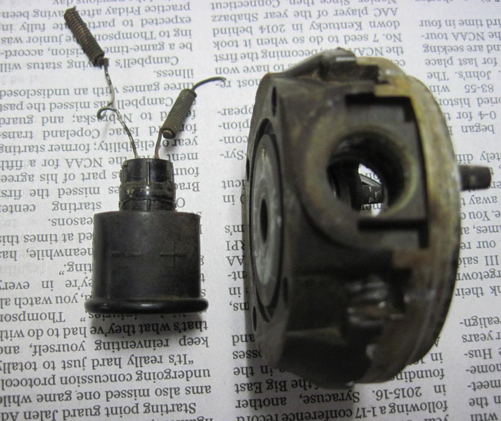 So, there you go. It’s a fairly simple and durable design, but unfortunately not one that can be easily rebuilt. All of the rubber parts in the pump were rock hard from age and fuel exposure. The o-rings should be able to be found fairly easily, but the seal on the check valve is a custom part and probably impossible to find -- if you ever have to take the check valve apart, don't try to remove this seal as you are highly-likely to break it. |
   |

 
|
Posts in this topic
 BillC 3-Port Fuel Pump Necropsy Jan 15 2017, 05:07 PM
 pbanders Excellent disassembly and analysis. We need this o... Jan 15 2017, 08:41 PM branston
3-port Fuel Pump Necropsy (i.e., what's in th... Jan 15 2017, 10:59 PM Frankvw Thanks a lot for your research and analysis.
You ... Jan 16 2017, 12:36 AM BillC Here's a small addendum:
The rotor runs in tw... Jan 16 2017, 11:01 AM Richard McLeod The three (3) port fuel pump is not as readily ava... Jan 28 2017, 12:36 AM
pbanders Excellent disassembly and analysis. We need this o... Jan 15 2017, 08:41 PM branston
3-port Fuel Pump Necropsy (i.e., what's in th... Jan 15 2017, 10:59 PM Frankvw Thanks a lot for your research and analysis.
You ... Jan 16 2017, 12:36 AM BillC Here's a small addendum:
The rotor runs in tw... Jan 16 2017, 11:01 AM Richard McLeod The three (3) port fuel pump is not as readily ava... Jan 28 2017, 12:36 AM 914_teener Yes, I have.
I wrote a thread on it and there are... Jan 28 2017, 12:59 AM
914_teener Yes, I have.
I wrote a thread on it and there are... Jan 28 2017, 12:59 AM  |
1 User(s) are reading this topic (1 Guests and 0 Anonymous Users)
0 Members:

|
Lo-Fi Version | Time is now: 29th May 2024 - 02:15 AM |
Invision Power Board
v9.1.4 © 2024 IPS, Inc.