|
|
|
Porsche, and the Porsche crest are registered trademarks of Dr. Ing. h.c. F. Porsche AG.
This site is not affiliated with Porsche in any way. Its only purpose is to provide an online forum for car enthusiasts. All other trademarks are property of their respective owners. |
|
|


| sarivers2001 |
 Oct 2 2023, 03:40 PM Oct 2 2023, 03:40 PM
Post
#1
|
|
Member  Group: Members Posts: 56 Joined: 16-August 23 From: California Member No.: 27,527 Region Association: Northern California |
Hello all. Sorry for the length of this post, but I have some questions for the community about my ‘74 914 2.0L’s heating system, which was removed in its entirety by my PO (he wanted to reduce weight to improve racing the car).
I am now inclined to build it all back in. I believe I have all of the major components, except heat exchangers (I am in the market for a pair still in very good shape or restored; too damn expensive new) and a bunch of the flexible pipes (which probably need to be replaced with new and better tubing anyway). The main Behr intake box under the cowl; the fan and motor beneath that; the 2 black plastic control boxes; the 2 black plastic dashboard defrost funnel vents - - I have all of these and they appear to be in good condition and generally just need a cleaning (the round rubber / foam seals on the valves are a little fried but I think I saw replacements for those being sold somewhere). The metal control boxes (with the “mushroom”-shaped heads) that connect to the heat exchangers in the back seem pretty well cooked and beat up, too, so those maybe need to be replaced as well. Regardless, my questions are as follows: 1) I have located 2 exploded diagrams for the system looking through books and on the web. One diagram shows the heat exchangers, metal control boxes and other related equipment in the lower back of the car. The other diagram shows the main intake box and main blower motor under the cowl, as well as their related hoses and equipment. What I cannot find is a diagram detailing the related equipment that belongs in the engine compartment, nor a diagram that shows how these 3 sections all connect up with one another. Is it fair to say that in the engine compartment, the only heater equipment is the “additional blower/motor” that attaches on the left side, behind the driver, next to the relay box, along with one (or two, if modified) hose(s) to holes at the bottom of the engine compartment? (I have seen recommendations for this mod/ update, i.e., from one hose to two hoses, using a splitter.). Thoughts on this? If I am understanding this correctly, this motor in the engine compartment would seem to be sucking air from the engine compartment and then pushing it through those pipes towards the heat exchangers? Right? Well, if so, then that heated air is then rerouted and somehow makes its way through the system to the passenger cabin, no? Is that safe (is that air clean enough and safely breathable)? Or do I have this backwards somehow? 2). Moreover, in studying the diagrams, I am having trouble understanding how that rear portion of the heating system air flow connects to the front portion of the heating system air flow. Are there separate hoses that are supposed to connect from each side corner on the rear firewall (see pictures below) up to the pipes behind the speakers (see picture below) and connecting up to the portion of the ventilation system in the front compartment)? Or, on both sides of the car, are there essentially metal pipes /passageways that are built into the frame / chassis / body of the car that makes this connection? If I am understanding this connection correctly, the main blower box under the cowl would seem to me to pulling fresh air from above, outside by the windshield, down these pipes towards the back of car, no? But, isn’t that backwards? Doesn’t it actually need to suck hot air from the back of the car up to the equipment in the front under the cowl and then somehow simultaneously push that hot air through the defroster and side vents in the dashboard? Here are some pics: In two of them you can see round metal openings in the top left and top right of the pictures that I refer to above, which seem to lead into the frame, and seem to lead to the pipes that come up behind the speakers? Is that correct? Are there supposed to flexible pipes in there somewhere that run down each side of the car - -or are the “pipes” / passageways built into the frame connecting these spots? Sorry again for the long post. Really appreciate any insights y’all can provide add here. Thanks, Steven Attached image(s) 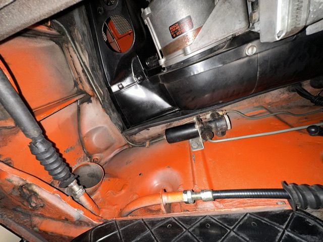 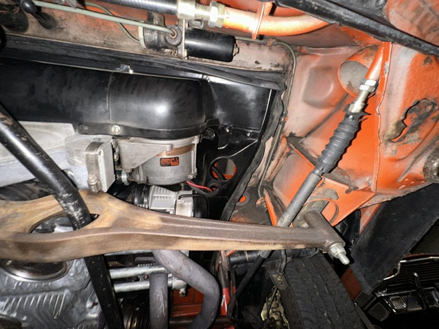 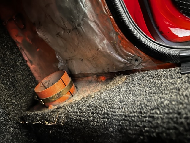
|
   |

 
|
Posts in this topic
 sarivers2001 Questions re: heating and ventilation system Oct 2 2023, 03:40 PM
 windforfun Those are your heater tube connectors. The tubes ... Oct 2 2023, 04:28 PM barefoot Dy you have the PET ? That's a complete brea... Oct 2 2023, 07:11 PM
 sarivers2001
Dy you have the PET ? That's a complete bre... Oct 2 2023, 07:28 PM Dave_Darling Here's some pics I took that I posted on Pelic... Oct 3 2023, 12:17 AM falcor75 The engine bay fan is the only one pushing warm ai... Oct 3 2023, 04:01 AM emerygt350 If the switch is set up correctly, you can turn th... Oct 3 2023, 06:23 AM sarivers2001 Many thanks to all for your responses.
In the mea... Oct 3 2023, 06:32 PM Mikey914 Not really sure that (unless you are running a tun... Oct 3 2023, 06:45 PM
sarivers2001
Dy you have the PET ? That's a complete bre... Oct 2 2023, 07:28 PM Dave_Darling Here's some pics I took that I posted on Pelic... Oct 3 2023, 12:17 AM falcor75 The engine bay fan is the only one pushing warm ai... Oct 3 2023, 04:01 AM emerygt350 If the switch is set up correctly, you can turn th... Oct 3 2023, 06:23 AM sarivers2001 Many thanks to all for your responses.
In the mea... Oct 3 2023, 06:32 PM Mikey914 Not really sure that (unless you are running a tun... Oct 3 2023, 06:45 PM  |
1 User(s) are reading this topic (1 Guests and 0 Anonymous Users)
0 Members:

|
Lo-Fi Version | Time is now: 4th June 2024 - 11:47 PM |
Invision Power Board
v9.1.4 © 2024 IPS, Inc.