|
|
|
Porsche, and the Porsche crest are registered trademarks of Dr. Ing. h.c. F. Porsche AG.
This site is not affiliated with Porsche in any way. Its only purpose is to provide an online forum for car enthusiasts. All other trademarks are property of their respective owners. |
|
|

  |

| SirAndy |
 Feb 4 2009, 10:26 PM Feb 4 2009, 10:26 PM
Post
#21
|
|
Resident German  Group: Admin Posts: 42,469 Joined: 21-January 03 From: Oakland, Kalifornia Member No.: 179 Region Association: Northern California |
QUOTE(Eric_Shea @ Feb 4 2009, 08:21 PM)  Looks to be angled at about a 15 degree downward angle sloping toward the wheel. And that car is significantly lowered? (IMG:style_emoticons/default/shades.gif) Andy |
   |

 
|
| Eric_Shea |
Feb 4 2009, 10:38 PM
Post
#22
|
|
PMB Performance Group: Admin Posts: 19,304 Joined: 3-September 03 From: Salt Lake City, UT Member No.: 1,110 Region Association: Rocky Mountains |
QUOTE And that car is significantly lowered? I don't think so... it looks to be a stock 1966 911 from the looks of the a-arm ball joint attachment. I would think that if it were significantly lowered, the a-arm would be more parallel than angled down (hence giving it a higher ride height). (IMG:style_emoticons/default/blink.gif) It's the stock factory manual "Vehicle Ride Height Adjustment" section. I don't think they aniticipated we would be jacking them down this low back then. I certainly don't think it would be listed as a factory proceedure for the shops. (IMG:style_emoticons/default/biggrin.gif) Work with me here... what's the best way to do this? I always heard parallel to the ground, hence parallel to the rack. |
|
|
|
| SirAndy |
Feb 4 2009, 10:44 PM
Post
#23
|
|
Resident German Group: Admin Posts: 42,469 Joined: 21-January 03 From: Oakland, Kalifornia Member No.: 179 Region Association: Northern California |
QUOTE(Eric_Shea @ Feb 4 2009, 08:38 PM) Work with me here... This is where i'm going with this: 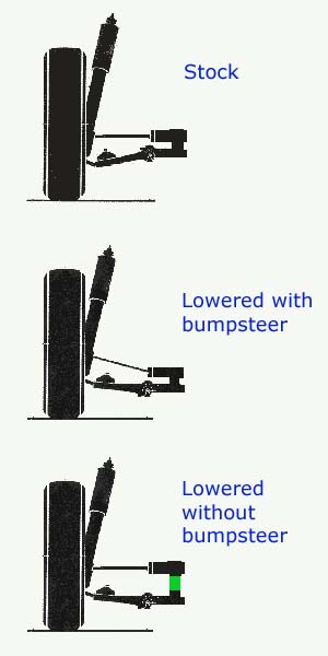 On a lowered car, you want to get your A-Arms as close to parallel to the ground as possible. Then either use rack-spacers (shown above) or a tie rod extensions to get the tie rods parallel to the A-Arms and the ground ... (IMG:style_emoticons/default/stirthepot.gif) Andy |
|
|
|
| SirAndy |
Feb 4 2009, 10:50 PM
Post
#24
|
|
Resident German Group: Admin Posts: 42,469 Joined: 21-January 03 From: Oakland, Kalifornia Member No.: 179 Region Association: Northern California |
Added the Tie Rod extension to the pic for clarification ...
(IMG:style_emoticons/default/type.gif) Andy Attached thumbnail(s) 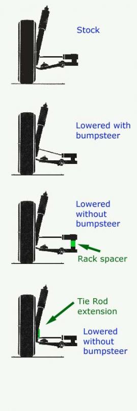
|
|
|
|
| Eric_Shea |
Feb 4 2009, 10:54 PM
Post
#25
|
|
PMB Performance Group: Admin Posts: 19,304 Joined: 3-September 03 From: Salt Lake City, UT Member No.: 1,110 Region Association: Rocky Mountains |
QUOTE On a lowered car, you want to get your A-Arms as close to parallel to the ground as possible. Hmmmmmmm... that would mean that Fig. 2 is OK because the a-arms are quite parallel to the ground. Also... what if I didn't want to lower it that much; would that be wrong? A parallel a-arm is not making sense. I'm sticking with the tie-rods parallel to the ground and the rack. because in Fig. 1 and Fig. 3+4 that's the constant. Fig. 1 shows a tie-rod that is correct and parallel. Fig. 3+4 shows a tie-rod that is supposedly correct and parallel. Me thinks you've been drink'n again. (IMG:style_emoticons/default/w00t.gif) |
|
|
|
| SirAndy |
Feb 4 2009, 11:01 PM
Post
#26
|
|
Resident German Group: Admin Posts: 42,469 Joined: 21-January 03 From: Oakland, Kalifornia Member No.: 179 Region Association: Northern California |
QUOTE(Eric_Shea @ Feb 4 2009, 08:54 PM) Hmmmmmmm... that would mean that Fig. 2 is OK because the a-arms are quite parallel to the ground. Are you deliberately misreading my posts? (IMG:style_emoticons/default/confused24.gif) I said, and that was when you started riding my ass, that both the A-Arms and Tie Rods should be parallel to each other on a lowered car. Then i said that on a lowered car, you want the A-Arms parallel to the ground. Combine the two, and on a lowered car you want the A-Arms parallel to the ground, the Tie Rods parallel to the A-Arms, which also makes the Tie Rods parallel to the ground. So, no Fig. 2 is NOT ok. In fact, it's the worst you can do in regards to bump steer. If you had taken the time to read my posts, that would have been clear ... (IMG:style_emoticons/default/slap.gif) Andy |
|
|
|
| Eric_Shea |
Feb 4 2009, 11:37 PM
Post
#27
|
|
PMB Performance Group: Admin Posts: 19,304 Joined: 3-September 03 From: Salt Lake City, UT Member No.: 1,110 Region Association: Rocky Mountains |
|
|
|
|
| Eric_Shea |
Feb 4 2009, 11:44 PM
Post
#28
|
|
PMB Performance Group: Admin Posts: 19,304 Joined: 3-September 03 From: Salt Lake City, UT Member No.: 1,110 Region Association: Rocky Mountains |
QUOTE Actually, if you're talking about bump steer, it's more important to get the tie rods parallel to the a-arms. And no I'm not riding your ass. I was actually curoius as to what you were talking about. I was going off your "original" comment and, after looking at the manual, I now think it's more important that the tie-rods be parallel to the ground, regardless of the a-arm. * If I'm stock, the a-arm is angled and the tie-rod is parallel to the ground. * If I lower just a little, the a-arm is still angled and the tie-rod should be parallel. * If I lower a lot, the a-arm can be parallel and hence so should the tie-rod. That's my reality and again, I wasn't riding you, I wanted clarity... which I found. |
|
|
|
| Krieger |
Feb 5 2009, 12:26 AM
Post
#29
|
|
Advanced Member Group: Members Posts: 4,847 Joined: 24-May 04 From: Santa Rosa CA Member No.: 2,104 Region Association: None |
Thank you Andy! very nice illustrations. Nice fat rack spacers are the true cheap, but problematic solution if you consider the rack will hit the sheet metal above.
QUOTE Also... what if I didn't want to lower it that much; would that be wrong? A parallel a-arm is not making sense. A arms parallel to the ground maximizes the distance between the two front wheels-widening the track. (each wheel swings in an arc -right?) Those illustrations are static and when the wheel goes up the angle at the rack changes. The important take away I'm getting is the relationship between the tie rod v the a arm. |
|
|
|
| SirAndy |
Feb 5 2009, 12:33 AM
Post
#30
|
|
Resident German Group: Admin Posts: 42,469 Joined: 21-January 03 From: Oakland, Kalifornia Member No.: 179 Region Association: Northern California |
QUOTE(Eric_Shea @ Feb 4 2009, 09:44 PM) I wasn't riding you (IMG:style_emoticons/default/gayfight.gif) At least *i* came up with some pretty pictures ... (IMG:style_emoticons/default/rolleyes.gif) Andy |
|
|
|
| ChrisFoley |
Feb 5 2009, 08:05 AM
Post
#31
|
|
I am Tangerine Racing Group: Members Posts: 8,019 Joined: 29-January 03 From: Bolton, CT Member No.: 209 Region Association: None |
QUOTE(Krieger914 @ Feb 5 2009, 01:26 AM) ... A arms parallel to the ground maximizes the distance between the two front wheels-widening the track. ... More acurately, positioning the a-arm so the center of the ball joint is at the same height as the center of the torsion bar will maximize the track width. There will be bump steer at some part of the range of travel, regardless of whether the arms are parallel to the a-arms or not. If you want bump steer to truly not be a factor it is essential to actually measure it on your setup, instead of making assumptions about what happens. There are dissimilarities between the arc of motion of the a-arm and the tie rod even when they are set parallel at rest. On my race car, I use a combination of rack spacers and bent steering arms to minimize the effects of bump steer. |
|
|
|
| Eric_Shea |
Feb 5 2009, 08:24 AM
Post
#32
|
|
PMB Performance Group: Admin Posts: 19,304 Joined: 3-September 03 From: Salt Lake City, UT Member No.: 1,110 Region Association: Rocky Mountains |
QUOTE The important take away I'm getting is the relationship between the tie rod v the a arm. The important take away I'm getting after looking at what are supposedly correct configurations (1, 3 & 4) is the tie-rod v the steering rack (or the ground). With raised spindles, which the factory did on certain RS's and all RSR's, it would be the tie-rod relationship that is changed. QUOTE If you want bump steer to truly not be a factor it is essential to actually measure it on your setup, instead of making assumptions about what happens. There are dissimilarities between the arc of motion of the a-arm and the tie rod even when they are set parallel at rest. On my race car, I use a combination of rack spacers and bent steering arms to minimize the effects of bump steer. So in my situation Chris, I would measure and use the factory 108 +/- number and add 18mm to the acceptable difference (Koni struts with spindles raised 18mm)? Adding rack spacers wouldn't help with the center of the torsion bar so, would I add the width of the spacers to the acceptable number as well? How much to bend my spindles on those if need be? |
|
|
|
| SirAndy |
Feb 5 2009, 10:11 AM
Post
#33
|
|
Resident German Group: Admin Posts: 42,469 Joined: 21-January 03 From: Oakland, Kalifornia Member No.: 179 Region Association: Northern California |
QUOTE(Eric_Shea @ Feb 5 2009, 06:24 AM) So in my situation Chris, I would measure and use the factory 108 +/- number and add 18mm to the acceptable difference (Koni struts with spindles raised 18mm)? Adding rack spacers wouldn't help with the center of the torsion bar so, would I add the width of the spacers to the acceptable number as well? How much to bend my spindles on those if need be? See, that's why i think the adjustable tie rod extensions might be a better choice than the rack spacers. A lot less questions ... (IMG:style_emoticons/default/biggrin.gif) We use them on the 911 track car and they have been holding up just fine for two full seasons now. I'm inclined to get a set for my 914 and ditch the rack spacers ... (IMG:style_emoticons/default/idea.gif) Andy |
|
|
|
| Krieger |
Feb 5 2009, 10:30 AM
Post
#34
|
|
Advanced Member Group: Members Posts: 4,847 Joined: 24-May 04 From: Santa Rosa CA Member No.: 2,104 Region Association: None |
So Andy with your configuration are you having any bump steer issues? On the street/track?
Andy |
|
|
|
| SirAndy |
Feb 5 2009, 10:55 AM
Post
#35
|
|
Resident German Group: Admin Posts: 42,469 Joined: 21-January 03 From: Oakland, Kalifornia Member No.: 179 Region Association: Northern California |
QUOTE(Krieger914 @ Feb 5 2009, 08:30 AM) So Andy with your configuration are you having any bump steer issues? On the street/track? On the 914, i currently run the generic off the shelf rack spacers. I still get bump steer as the geometry is not quite right. Certainly better than what it was without the spacers, but not perfect. However, the problem is really only on the street as most tracks around here are smooth enough for my current setup. The bay area roads are a completely different story, however. (IMG:style_emoticons/default/dry.gif) Andy |
|
|
|
| Eric_Shea |
Feb 5 2009, 12:21 PM
Post
#36
|
|
PMB Performance Group: Admin Posts: 19,304 Joined: 3-September 03 From: Salt Lake City, UT Member No.: 1,110 Region Association: Rocky Mountains |
QUOTE See, that's why i think the adjustable tie rod extensions might be a better choice than the rack spacers. A lot less questions ... Agreed... that may simply solve all my issues. |
|
|
|
| charliew |
Feb 5 2009, 12:31 PM
Post
#37
|
|
Advanced Member Group: Members Posts: 2,363 Joined: 31-July 07 From: Crawford, TX. Member No.: 7,958 |
Ok the simple explanation is as Chris and Andy's nice art work states is that:
The tierod needs to be exactly the same length from it's inner ball joint to the end at the spindle arm as the a-arm from the inner bushings to the balljoint so that they stay parallel and swing in the exact same arc. If the steering rack is two inches higher and three inches further rearward from the inner a-arm bushings the spindle arm end for the tierod needs to be 2 inches above the balljoint and three inches rearward of it. Actually a straight line at rest between the tierod ends. If this ain't so you gotta set it at ride heigth and limit the travel of the suspension so the bump steer is as little as you can get it. The limited travel is what makes it not keep the wheels on the ground under normal use. It seems that track cars may not need the extral travel that you need on a street car. How much you lower the car seems to be relative to when the tire will touch the fender lip when it is turned and bottomed out. If you are trying to keep the full motion of a strut insert on a lowered fat front tired 914, Can you make a piece that is the same length as a bottomed strut insert and put it in the strut and use that as the starting place with your chosen front wheel to see where to put the rack and spindle in relation to the strut? It seems that when you bend the tierod end of the spindle arm down it gets shorter and that will quicken steering but will change the relationship of the arcs. If you guys know a place to get this info for the 914 please enlighten me, I'm sure I'm not the first dummy to study this. |
|
|
|
| sww914 |
Feb 5 2009, 06:56 PM
Post
#38
|
|
Advanced Member Group: Members Posts: 2,439 Joined: 4-June 06 Member No.: 6,146 Region Association: None |
I like this bump steer kit- http://www.rebelracingproducts.com/Suspension/Steering.html
bit cheaper and one less part to fail than the Elephant racing kit. AFAIK everything that Elephant makes is good but none of it is cheap. |
|
|
|
| Krieger |
Feb 5 2009, 07:38 PM
Post
#39
|
|
Advanced Member Group: Members Posts: 4,847 Joined: 24-May 04 From: Santa Rosa CA Member No.: 2,104 Region Association: None |
Smart has one that looks much the same for $309. Its called an ERP bump steer. Do you think ERP=elephant racing products? But I didn't see this listed in their catalogue. Elephant has a way cool $360 one that looks much stronger.
|
|
|
|
| ChrisFoley |
Feb 6 2009, 10:17 AM
Post
#40
|
|
I am Tangerine Racing Group: Members Posts: 8,019 Joined: 29-January 03 From: Bolton, CT Member No.: 209 Region Association: None |
QUOTE(Eric_Shea @ Feb 5 2009, 09:24 AM) So in my situation Chris, I would measure and use the factory 108 +/- number and add 18mm to the acceptable difference (Koni struts with spindles raised 18mm)? Adding rack spacers wouldn't help with the center of the torsion bar so, would I add the width of the spacers to the acceptable number as well? How much to bend my spindles on those if need be? My technique is to bend the steering arm equal to the amount the spindle is raised, then use rack spacers to correct for any additional lowering. You could also use heim joint tie rods with spacers of 18mm and rack spacers, or all tie rod spacers. What I meant by "actually measure it" is to use bump steer measuring tools and move the strut up and down with no torsion bar installed. Bump steer tools use a flat plate bolted to the hub and two dial indicators to show the steering effect as the strut is moved. It is a trial and error process to move the bump steer effect to a part of suspension travel where it has less influence. You want the bump steer to be minimized close to ride height, especially in compression. In rebound any bump steer will have little effect since the wheel is unloaded. |
|
|
|
|
1 User(s) are reading this topic (1 Guests and 0 Anonymous Users)
0 Members:

|
Lo-Fi Version | Time is now: 2nd April 2026 - 11:23 AM |
Invision Power Board
v9.1.4 © 2026 IPS, Inc.