|
|
|
Porsche, and the Porsche crest are registered trademarks of Dr. Ing. h.c. F. Porsche AG.
This site is not affiliated with Porsche in any way. Its only purpose is to provide an online forum for car enthusiasts. All other trademarks are property of their respective owners. |
|
|

  |

| mtbr_mark |
 Aug 5 2009, 01:16 PM Aug 5 2009, 01:16 PM
Post
#1
|
|
Newbie  Group: Members Posts: 39 Joined: 7-April 09 From: Oregon Member No.: 10,247 Region Association: None |
Hi guys. I'm buttoning up a 914-6 conversion right now and ran into a problem the other night when I got the wiring hooked up (big surprise huh?). Turned the key to the on position then saw a waft of smoke floating by. Smoked the wires going to the hot side of the coil. I'm looking for anyone that's put a 2.0-6cyl engine into their 914 that can help. I've read tons and tons of posts on here about how the coil needs to be wired up but the problem comes in that everyone seems to give advice on wiring a 4-cyl coil (i.e. black/purple wire goes to one side and then black wire to other, blah blah blah).
I attached a quick schematic of how the 914-6 wiring is between the coil, the battery, the distributor, the Ignition box, and the relay board. As you can see there are a set of black/red wires coming from the relay board to the coil and the CD box. With the 4-cyl wiring harness there's only one black/red wire. Anyhow, enough of my monologue here. Any help at all on how all my wiring needs to be to make my 1970 914-6 2.0 6cylinder motor work (wiring wise) in my 1971 914-4 2.0 4-cylinder car would be greatly appreciated. 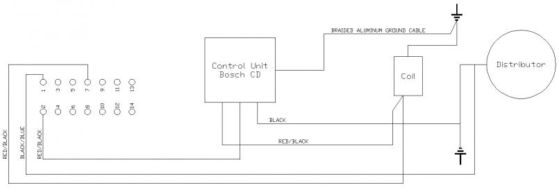 Thanks, Mark |
   |

 
|
| ClayPerrine |
Aug 5 2009, 03:55 PM
Post
#2
|
|
Life's been good to me so far..... Group: Admin Posts: 16,526 Joined: 11-September 03 From: Hurst, TX. Member No.: 1,143 Region Association: NineFourteenerVille |
This should help.....
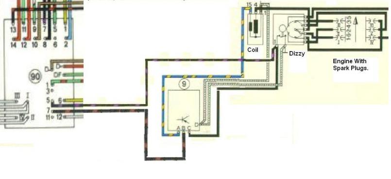 But you won't have a tach if you use the factory 914-6 tach. There is no place for a tach amplifier. Use the tach out of an 911 SC and it will work fine. |
|
|
|
| mtbr_mark |
Aug 5 2009, 11:56 PM
Post
#3
|
|
Newbie Group: Members Posts: 39 Joined: 7-April 09 From: Oregon Member No.: 10,247 Region Association: None |
QUOTE(ClayPerrine @ Aug 5 2009, 02:55 PM)  This should help..... But you won't have a tach if you use the factory 914-6 tach. There is no place for a tach amplifier. Use the tach out of an 911 SC and it will work fine. I think that's exactly what I'm looking for. Thanks Clay. Just out of curiosity, have you personally wired up a 6-cylinder car using this info? |
|
|
|
| ClayPerrine |
Aug 6 2009, 07:13 AM
Post
#4
|
|
Life's been good to me so far..... Group: Admin Posts: 16,526 Joined: 11-September 03 From: Hurst, TX. Member No.: 1,143 Region Association: NineFourteenerVille |
[quote name='mtbr_mark' date='Aug 6 2009, 12:56 AM' post='1199962']
[quote name='ClayPerrine' post='1199731' date='Aug 5 2009, 02:55 PM'] This should help..... But you won't have a tach if you use the factory 914-6 tach. There is no place for a tach amplifier. Use the tach out of an 911 SC and it will work fine. [/quote] I think that's exactly what I'm looking for. Thanks Clay. Just out of curiosity, have you personally wired up a 6-cylinder car using this info? [/quote I drew the diagram, and I guarantee it works. I built the wiring harness for my 73 six conversion car using a 73 914 harness, a 914-6 relay board, and parts of a 68 912 harness and a 75 911 harness. Yes, it will work, but like I said, you need an SC tach. The CD box on a 911 uses a lower voltage through the points, so there is not enough to fire the tach. When Porsche added the CD box to the 911, they used a "tach amplifier" which uppped the voltage to the tach, and they used the exact same parts on the 914-6. Later Porsche recalibrated the tach to work with the lower voltage. Maybe I should start building 914/6 conversion harnesses?? (IMG:style_emoticons/default/idea.gif) |
|
|
|
| mtbr_mark |
Aug 6 2009, 07:59 AM
Post
#5
|
|
Newbie Group: Members Posts: 39 Joined: 7-April 09 From: Oregon Member No.: 10,247 Region Association: None |
QUOTE I drew the diagram, and I guarantee it works. Maybe I should start building 914/6 conversion harnesses?? (IMG:style_emoticons/default/idea.gif) Perfect. I hope I didn't come across as rude when I asked if you'd done this I just wanted to make sure that the rubber had met the road before I ran any current through my system again. Thank you VERY VERY much for the help. I'll get everything up and going like you suggest. Any leads on where to find a 911 SC Tach? (IMG:style_emoticons/default/smile.gif) |
|
|
|
| ClayPerrine |
Aug 6 2009, 08:14 AM
Post
#6
|
|
Life's been good to me so far..... Group: Admin Posts: 16,526 Joined: 11-September 03 From: Hurst, TX. Member No.: 1,143 Region Association: NineFourteenerVille |
QUOTE(mtbr_mark @ Aug 6 2009, 08:59 AM) QUOTE I drew the diagram, and I guarantee it works. Maybe I should start building 914/6 conversion harnesses?? (IMG:style_emoticons/default/idea.gif) Perfect. I hope I didn't come across as rude when I asked if you'd done this I just wanted to make sure that the rubber had met the road before I ran any current through my system again. Thank you VERY VERY much for the help. I'll get everything up and going like you suggest. Any leads on where to find a 911 SC Tach? (IMG:style_emoticons/default/smile.gif) No insult taken.. I just wanted you to know I have been doing stuff like this for years. And I am always happy to help. Check with Zims in Texas. 1-800-356-2964. They have 2 wrecked 911 SCs that are being parted right now. |
|
|
|
| IronHillRestorations |
Aug 6 2009, 09:57 AM
Post
#7
|
|
I. I. R. C. Group: Members Posts: 6,887 Joined: 18-March 03 From: West TN Member No.: 439 Region Association: None |
I've got correct color coded wire, PVC jacketing, heat shrink, to last the rest of your life, make me an offer!
|
|
|
|
| Jeffs9146 |
Aug 6 2009, 10:05 AM
Post
#8
|
|
Ski Bum Group: Members Posts: 4,062 Joined: 10-January 03 From: Discovery Bay, Ca Member No.: 128 |
|
|
|
|
| Cap'n Krusty |
Aug 6 2009, 10:42 AM
Post
#9
|
|
Cap'n Krusty Group: Members Posts: 10,794 Joined: 24-June 04 From: Santa Maria, CA Member No.: 2,246 Region Association: Central California |
QUOTE(Jeffs9146 @ Aug 6 2009, 09:05 AM) Any Porsche tach from around 1972 through 1983 will work. You can also send your 4 cyl. tach to North Hollywood Speedometer or Palo Alto Speedometer for modification and service. The Cap'n |
|
|
|
| mtbr_mark |
Aug 9 2009, 04:53 PM
Post
#10
|
|
Newbie Group: Members Posts: 39 Joined: 7-April 09 From: Oregon Member No.: 10,247 Region Association: None |
Clay,
Sorry to keep bugging you but I do have one final question. I'm a bit concerned. I wired everything up exactly as you've shown me how with your diagram but before I hook any power up to anything I'm trying to double check everything with my multi-meter. When I check I see that I have continuity between pin 7 (which leads to the CD box and then to the coil) and ground. Is that continuity coming because the coil and CD box are both grounded? It concerns me that a pin that's going to have 12 volts running through it shows continuity between itself and ground. Any advice? Thank you, Mark |
|
|
|
| ClayPerrine |
Aug 9 2009, 05:04 PM
Post
#11
|
|
Life's been good to me so far..... Group: Admin Posts: 16,526 Joined: 11-September 03 From: Hurst, TX. Member No.: 1,143 Region Association: NineFourteenerVille |
QUOTE(mtbr_mark @ Aug 9 2009, 05:53 PM) Clay, Sorry to keep bugging you but I do have one final question. I'm a bit concerned. I wired everything up exactly as you've shown me how with your diagram but before I hook any power up to anything I'm trying to double check everything with my multi-meter. When I check I see that I have continuity between pin 7 (which leads to the CD box and then to the coil) and ground. Is that continuity coming because the coil and CD box are both grounded? It concerns me that a pin that's going to have 12 volts running through it shows continuity between itself and ground. Any advice? Thank you, Mark Mark, Pin seven on the relay board ONLY goes to pin B (the middle connection) on the CD box. There is no connection anywhere else. The positive side of the coil goes to pin A on the CD box. Pin 5 on the relay board connects to the points and connection C on the CD box. That is the trigger line and can be connected to ground. There is no direct connection between the coil and the relay board. The positive side of the coil comes from pin A on the CD box, and the negative side is connected directly to ground. Sounds like you have something wired wrong. Recheck everything, and make the continuity checks with the CD box and the coil disconnected. |
|
|
|
| messix |
Aug 9 2009, 05:17 PM
Post
#12
|
|
AKA "CLUTCH KILLER"! Group: Members Posts: 6,995 Joined: 14-April 05 From: between shit kickers and pinky lifters/ puget sound wa.north of Seattle south of Canada Member No.: 3,931 Region Association: Pacific Northwest |
check to make sure that the 14 pin connector at the relay board is on right, i smoked my tach wire by getting the connector on one set of pins off to the rear.
|
|
|
|
|
1 User(s) are reading this topic (1 Guests and 0 Anonymous Users)
0 Members:

|
Lo-Fi Version | Time is now: 8th November 2025 - 04:13 AM |
Invision Power Board
v9.1.4 © 2025 IPS, Inc.