|
|
|
Porsche, and the Porsche crest are registered trademarks of Dr. Ing. h.c. F. Porsche AG.
This site is not affiliated with Porsche in any way. Its only purpose is to provide an online forum for car enthusiasts. All other trademarks are property of their respective owners. |
|
|

  |

| Valy |
 Apr 2 2013, 10:42 AM Apr 2 2013, 10:42 AM
Post
#81
|
|
Senior Member  Group: Members Posts: 1,677 Joined: 6-April 10 From: Sunnyvale, CA Member No.: 11,573 Region Association: Northern California |
The measurement you should care about is the axial play of the gears. I see some wear marks in the cap but you need to check how deep are those marks.
|
   |

 
|
| AE354803 |
Apr 2 2013, 10:47 AM
Post
#82
|
|
Member Group: Members Posts: 238 Joined: 13-August 12 From: Southern California Member No.: 14,801 Region Association: Southern California |
I can really only measure axial movement for the driving gear after it's assembled due to the design of the pump. There was no perceivable play in it while assembled though. The "grooves" are basically just scratches, not of any significant depth but they can be felt with a fingernail.
I'm contemplating assembling it with a bit of lapping compound on the gear to housing mating surface and lapping it for a little. The would be a last chance effort and only if I had a suitable replacement pump in hand, just incase. I want to see if it can be refurbished. |
|
|
|
| Valy |
Apr 2 2013, 12:48 PM
Post
#83
|
|
Senior Member Group: Members Posts: 1,677 Joined: 6-April 10 From: Sunnyvale, CA Member No.: 11,573 Region Association: Northern California |
Lapping compound can't do any good. If you insist, you need to remove the idle axle and flycut the surface to make it straight but I think you're as it is now. Then... it will be prone to idle axle failure.
|
|
|
|
| AE354803 |
Apr 3 2013, 12:55 AM
Post
#84
|
|
Member Group: Members Posts: 238 Joined: 13-August 12 From: Southern California Member No.: 14,801 Region Association: Southern California |
What brand of bearings are the most reliable?
Connecting rods: Kolbenschmidt vs Mahle Mains: Mahle vs Silverline (does STD/STD/STD vs .10/STD/STD mean that the ID (crank) is 0.1" under? or case is 0.1" under? I'm guessing it's ID/OD/WIDTH) |
|
|
|
| VaccaRabite |
Apr 3 2013, 08:49 AM
Post
#85
|
|
En Garde! Group: Admin Posts: 13,845 Joined: 15-December 03 From: Dallastown, PA Member No.: 1,435 Region Association: MidAtlantic Region |
There are those who will disagree with me and say that this is a job easily done at home, but it is to your advantage to have a machinist tell you what bearings you need set bearing tolerance.
In a T4 it's hard to use plastigauge on all the bearings as the are not all split. Your machinist will also be better equipped to make changes needed to have bearings fit properly. Buying the correct size bearings is only part of the puzzle. Are you sure your case is still perfectly aligned? what about the crank? Do you know the case mods needed to change bearing tolerance (and have the equipment to do it? There is a lot of engine work can be done at home. But there are reasons why even the pros use machinists for parts of a build. Zach |
 |
|
| Valy |
Apr 3 2013, 02:25 PM
Post
#86
|
|
Senior Member Group: Members Posts: 1,677 Joined: 6-April 10 From: Sunnyvale, CA Member No.: 11,573 Region Association: Northern California |
QUOTE(AE354803 @ Apr 2 2013, 11:55 PM)  What brand of bearings are the most reliable? Connecting rods: Kolbenschmidt vs Mahle Mains: Mahle vs Silverline (does STD/STD/STD vs .10/STD/STD mean that the ID (crank) is 0.1" under? or case is 0.1" under? I'm guessing it's ID/OD/WIDTH) Sometimes yes. I found that some sellers mix the measurements. Anyway, T4 bearings are only available in different crank and case journals so the 3rd measurement (thrust) is always STD. The case is only STD or +.5mm. Crank is available in -0.25mm jumps. So the .10 you see is -.25mm on the crank. |
|
|
|
| AE354803 |
Apr 13 2013, 04:53 PM
Post
#87
|
|
Member Group: Members Posts: 238 Joined: 13-August 12 From: Southern California Member No.: 14,801 Region Association: Southern California |
Got the heads back, installed the solid spacers while I have free time. Waiting on the case and rods, once bearings come in it's time to rebuild.
Does anyone know the ID of a new crank timing gear? I have a used one with 1.65225" ID New shaft is 1.6540" and the Tom Wilson book says interference is supposed to be 0.004" so I'm a little low at .00175". I've seen new gears on AA for $85, I've found a pile for type 1/3's but I don't think its the same part # Although aircooled's type 4 dist gear is on 1200-1600 engines and their steel timing gear is for 1200-1600 cc engines also, seems like it should be the same part, just different numbers. http://vwparts.aircooled.net/Distributor-D...111-105-223.htm http://vwparts.aircooled.net/Crankshaft-Ti...3-105-209oe.htm AA has the dist gear as 901 102 115 00 (aircooled has 111-105-223) and crank gear as 021 105 209 A (aircooled 1200-1600 cc has 113-105-209) I'm thinking that since the dist gear fits the same shaft, so long as it has the same amount of teeth the crank gear should be the same (assuming same gear dimensions) 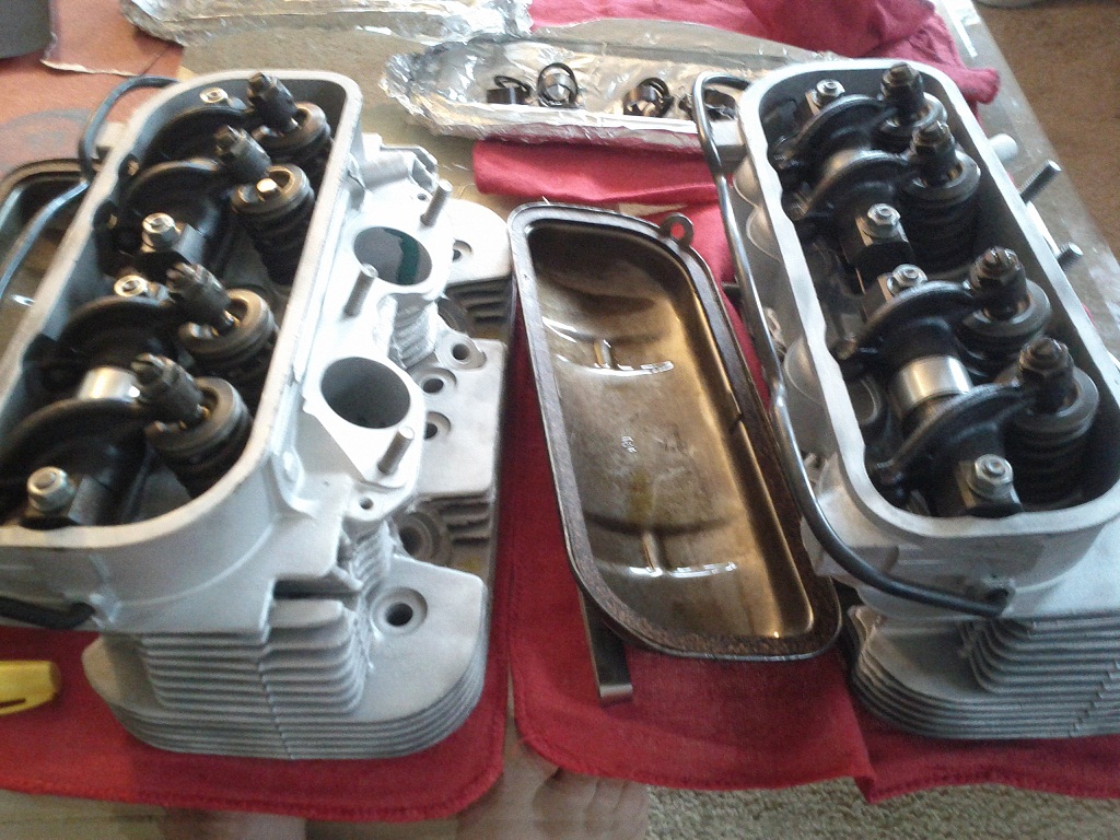 |
|
|
|
| AE354803 |
Apr 30 2013, 08:39 PM
Post
#88
|
|
Member Group: Members Posts: 238 Joined: 13-August 12 From: Southern California Member No.: 14,801 Region Association: Southern California |
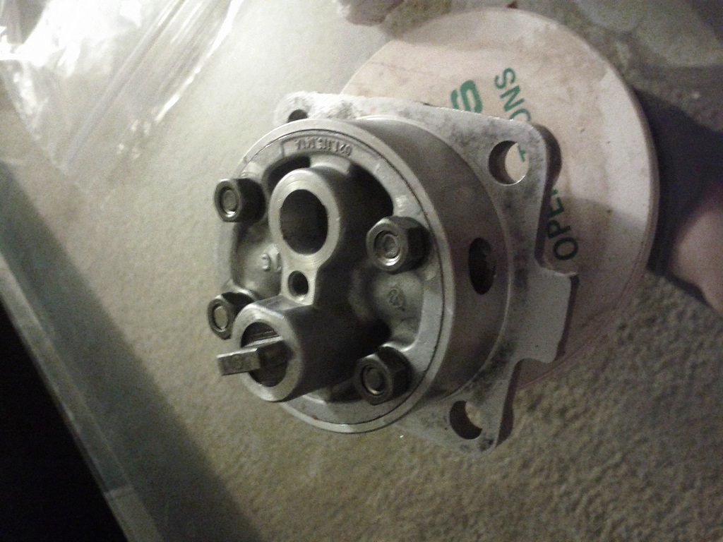
I'm rebuilding the oil pump in preparation for short block assembly this weekend.
I can't find the torque for the 4 bolts on the rear (inside the case) of the type 4 pump. Check haynes, 914 handbook and Tom Wilson book with no luck. Anyone know this torque spec? |
|
|
|
| pilothyer |
Apr 30 2013, 09:33 PM
Post
#89
|
|
Member Group: Members Posts: 838 Joined: 21-May 08 From: N. Alabama Member No.: 9,080 Region Association: South East States |
Oil pump to crankcase nuts 14 ft lb according to:
http://www.tunacan.net/t4/reference/torque.htm |
|
|
|
| pilothyer |
Apr 30 2013, 09:34 PM
Post
#90
|
|
Member Group: Members Posts: 838 Joined: 21-May 08 From: N. Alabama Member No.: 9,080 Region Association: South East States |
My bad.....wrong bolts per your question
|
|
|
|
| AE354803 |
Apr 30 2013, 09:39 PM
Post
#91
|
|
Member Group: Members Posts: 238 Joined: 13-August 12 From: Southern California Member No.: 14,801 Region Association: Southern California |
Got that spec, thanks though. I'm looking for the 4 small nuts on the back of the pump, the ones that hold it together (type 4 pump)
 |
|
|
|
| pilothyer |
Apr 30 2013, 10:04 PM
Post
#92
|
|
Member Group: Members Posts: 838 Joined: 21-May 08 From: N. Alabama Member No.: 9,080 Region Association: South East States |
As a builder of many type 4 engines as well as a proponent of using the type 4 pump I'm sure I use 5 ft lbs torque on these four 6 mm nuts. This along with the spring washers should be plenty. I have combed over the factory manual for the information but haven't had any luck finding it.
|
|
|
|
| Java2570 |
May 1 2013, 06:18 AM
Post
#93
|
|
Senior Member Group: Members Posts: 649 Joined: 7-May 11 From: Fishers, IN Member No.: 13,035 Region Association: Upper MidWest |
I'm pretty sure that in his video, Jake mentions there is no real torque value on those nuts but just get em good and snug. I would say 5 ft lb is about right
|
|
|
|
| AE354803 |
May 1 2013, 11:07 AM
Post
#94
|
|
Member Group: Members Posts: 238 Joined: 13-August 12 From: Southern California Member No.: 14,801 Region Association: Southern California |
Sound good to me. Maybe I'll throw some blue loctite on there for good measure.
|
|
|
|
| AE354803 |
May 5 2013, 11:43 PM
Post
#95
|
|
Member Group: Members Posts: 238 Joined: 13-August 12 From: Southern California Member No.: 14,801 Region Association: Southern California |
Where can I remove material from the Keith Black pictures in order to static balance? There is no ridge across the center and I do not want to remove material that is not along the centerline of the piston following the pin.
Also I'm looking for the small (2mm x 8 mm) dowel pins that keep the bearings from rotating. I have 4 out of 5 of them. AA - bearing pin 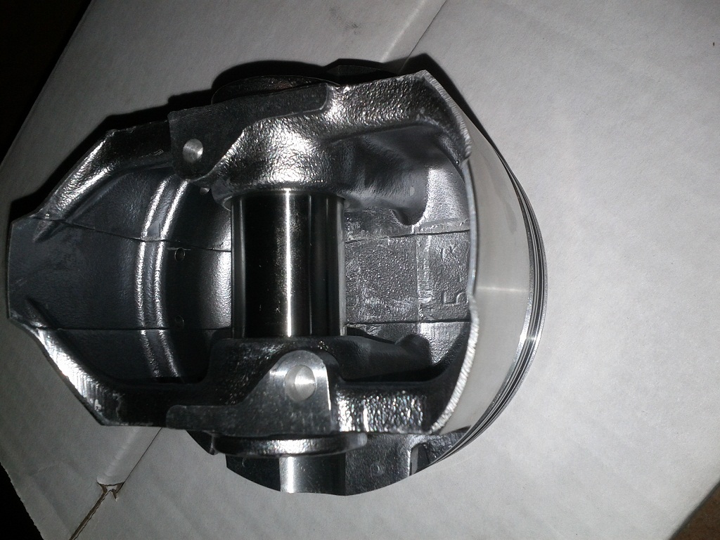 |
|
|
|
| AE354803 |
May 8 2013, 01:08 PM
Post
#96
|
|
Member Group: Members Posts: 238 Joined: 13-August 12 From: Southern California Member No.: 14,801 Region Association: Southern California |
I've been looking at the pistons and I think I'll remove material from the balance holes that have been drilled into the bottom of the wrist pin area. I figure that I'll just chamfer/countersink the top edge a little bit and it shouldn't affect the strength.
I'm not sure on whether to remove material uniformly from the hole of take more from the portions furthest from the wrist pin since these areas would affect strength even less. I only need to remove a max of 1 gram of material to get them balanced. Any thoughts? On a side note. There was no distributor drive pinion shim (021-105-235) in the engine when I disassembled, this part is surprisingly difficult to source. None of my local shops have it. |
|
|
|
| AE354803 |
May 8 2013, 06:43 PM
Post
#97
|
|
Member Group: Members Posts: 238 Joined: 13-August 12 From: Southern California Member No.: 14,801 Region Association: Southern California |
I'm measuring the piston-cylinder gap. Spec is 0.0021 - 0.0029 inches (wear limit of 0.007").
I have new Keith Black 96 mm and new EMW 96 mm cylinders (which from everything I read are really good) It seems like I have a very tight tolerance on the tall portion of the piston skirt I can't even fit a gauge in (0.001 is my smallest but I don't want to force it) (perpendicular to the wrist pin) (see yellow arrow) The clearance at the edges of the skirt are in spec (0.00225-0.00275") (see green arrow) The clearance on the wrist pin portions are very loose (I would guess about 0.010" which is hard to measure because of the curve of the cylinder/piston) (see red arrow) I understand the tight fit on the tall portions of the skirt since that is where most of the wear will come due to the piston rocking, however the extra slop on the sides seems excessive, any advice on this? If I rotate the piston in the cylinder it maintains the same clearances, so it seems the pistons are purposely out of round and the cylinder is very cylindrical. Thanks for any help... 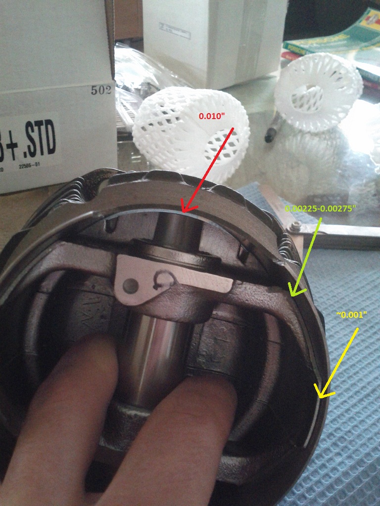 |
|
|
|
| Valy |
May 8 2013, 07:56 PM
Post
#98
|
|
Senior Member Group: Members Posts: 1,677 Joined: 6-April 10 From: Sunnyvale, CA Member No.: 11,573 Region Association: Northern California |
All pistons have oval skirts as you measured.
The top however must be round. |
|
|
|
| AE354803 |
May 8 2013, 09:19 PM
Post
#99
|
|
Member Group: Members Posts: 238 Joined: 13-August 12 From: Southern California Member No.: 14,801 Region Association: Southern California |
The top had the same large gap all the way around, seems like I'm good then.
Any input on where to remove material for the static balance? |
|
|
|
| AE354803 |
May 11 2013, 06:57 PM
Post
#100
|
|
Member Group: Members Posts: 238 Joined: 13-August 12 From: Southern California Member No.: 14,801 Region Association: Southern California |
During platigage fit today, found out the cam thrust bearings are too tight, they jam onto the camshaft and stay on it, I had to push the camshaft a bit to get it in there.
Does this sound normal? The thrust portion of the thrust bearing seems to be too big and jams in the camshaft, has to be pried off after the camshaft is removed. I have kolbenschmidt bearings, should I switch to something else? |
|
|
|
|
1 User(s) are reading this topic (1 Guests and 0 Anonymous Users)
0 Members:

|
Lo-Fi Version | Time is now: 2nd April 2026 - 09:51 AM |
Invision Power Board
v9.1.4 © 2026 IPS, Inc.