|
|
|
Porsche, and the Porsche crest are registered trademarks of Dr. Ing. h.c. F. Porsche AG.
This site is not affiliated with Porsche in any way. Its only purpose is to provide an online forum for car enthusiasts. All other trademarks are property of their respective owners. |
|
|

  |

| Larry.Hubby |
 Jan 28 2010, 10:51 PM Jan 28 2010, 10:51 PM
Post
#1
|
|
Member who doesn't post much, but has a long time in 914s  Group: Members Posts: 188 Joined: 24-November 04 From: Palo Alto, CA Member No.: 3,172 Region Association: Northern California |
I’ve seen some threads on changing the instrument bulbs to LEDs, and noticed that several of the respondents have wanted a scheme, not only for dimming the LEDs, but one that also uses the existing rheostat built into the headlight switch to do this. I built a system like this for my car, so I thought I’d post a how-to covering what I did.
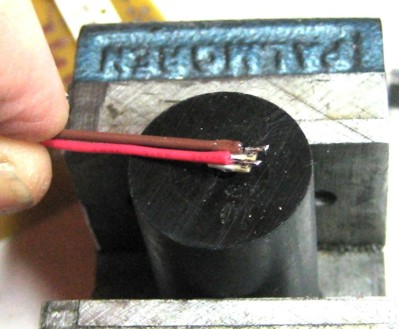
I apologize in advance that my description is so long and detailed. I did it this way because I’ve noticed several people here claim to know little or nothing about things electrical. Those of you familiar with electronics can skip ahead to the circuit and substitute your own practices for what I did in many places. The positive features of my scheme are: 1. No need to disassemble the gauges to install the LEDs. 2. Uses the existing dimming control in the headlight switch. 3. Easily provides 2-3 times the light output of the original instrument bulbs, while drawing half the power. If desired, even more light is available by re-adjusting circuit parameters. And, as with any scheme, there are always prices to be paid: 1. The LEDs require some work to mount. 2. Some re-wiring and construction of external circuitry is necessary, although the circuitry involved is very simple and quite inexpensive. 3. The LEDs are rather expensive (~$5/ea), but only 6 are required (for a standard 3 gauge 914 instrument panel; 8 are needed for the 911-style 5 gauge panels that some of us, myself included, have). My basic approach is to use high power LEDs designed for general lighting applications, one to replace each existing instrument bulb, instead of a large number of much lower-powered LEDs. Instead of having a maximum current rating of 30ma like most small LEDs, these can be driven with up to 1 amp and produce correspondingly more light. This higher current draw is what makes it feasible to use the existing dimmer rheostat, although some additional circuitry is still required to get both the desired brightness and a wide dimming range simultaneously. The LEDs I’m talking about are the Lumileds Luxeon Rebel series, which look like this: 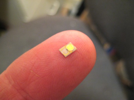 They’re small, just 3 x 4.5 mm, and available in colors from red to blue, and three versions of white. The data sheet for the general purpose white ones is available on-line at: http://www.philipslumileds.com/pdfs/DS64.pdf, and small quantities can be purchased on-line at: http://www.philipslumileds.com/products/luxeon-rebel-white . First click on the color you’re interested in under “Products”, then find a part that has a small shopping cart icon on the left in the list that opens up. If the icon is that of a telephone, rather than a shopping cart, that particular part is not available in small quantities. A click on this icon will take you to the Future Electronics website, an online dealer for Lumileds parts. For the case of warm white parts, which will produce light closest to the stock appearance, the part number I recommend is LXML-PWW1-0050. These were available in small quantities as of the date of this writing at a price of $4.73 ea. The package size of the Rebel parts is small enough that we can mount them in the same locations as the existing bulbs, although this isn’t quite as straightforward as it may appear, and will be described in detail later. We can get all the design info we need for this application from the datasheet and the following set of measurements. Below is a graph of measured data for light output vs current, comparing one of these warm-white LED to a stock 2 watt instrument bulb: 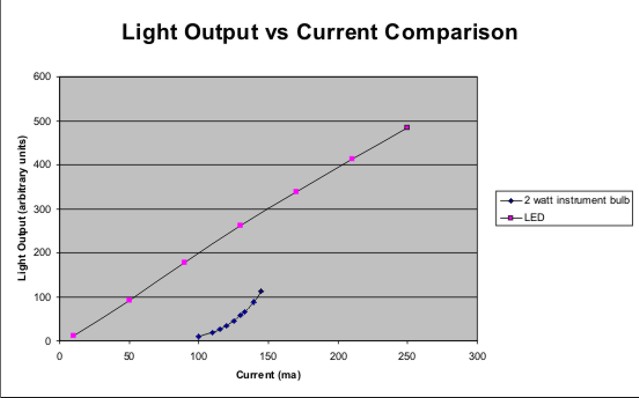 The upper curve is the LED and the lower one is the stock bulb. As you can see, in addition to producing over twice the light at the same current as the full-on bulb, the LED’s output is nearly linear vs current, while the bulb still draws 2/3 of the full-on current when dimmed nearly out. Consider also that the LED is running on about 3.2 volts at 150 ma while the bulb needs nearly 13 volts at the same current. In the stock arrangement in the car, there are six of these illumination bulbs running in parallel, two in each instrument, so the total current is about 900ma. We can hook up the LEDs in series/parallel combinations to make up part of the voltage miss-match between the 12V car electrical system and the LED requirements, and to share the same current among more than one LED. It might be tempting to use four LEDs in series, which would add up to a voltage requirement of 12.8 volts at ~150ma, which is almost exactly actual battery voltage. I have tried using two such series strings of four LEDs in parallel for the 5 gauge dash in my car, and it does work, however, it is not a very good solution for several reasons. Since the combined current draw of the two strings is only 300ma instead of the 900ma that the rheostat is designed for, and since the LEDs dim more linearly with current than the bulbs, the dimming range is reduced to about 2:1 instead of about 10:1. Also, the LEDs respond instantly to changes in current, which can be caused by system voltage fluctuations due to the action of the voltage regulator or large current load changes, while the stock bulbs tend to average these changes out a bit because of their thermal “inertia”. So, if we hook things up this way, the instrument illumination will often flicker with changes in engine speed, etc. The voltage requirements of LEDs also tend to change a bit over time and “age’ with use, and, although the change is small, it doesn’t take much change in terms of voltage to greatly change the current draw of the LEDs. If the aging increases the voltage requirement, the brightness can drop permanently and substantially, leaving you wondering what happened to your LEDs that are supposed to last forever. Another potential problem is protection from damage due to reverse-voltage spikes that can occur in a car’s electrical system due to inductive components like relay coils, electric motors and alternators. LEDs are diodes, but, due to their structure, they have very little ability to withstand reverse voltage. Hooking them up backwards to a source designed to run them usually won’t hurt, but inductive spikes can often reach over a hundred volts, and even a brief reverse spike of that magnitude can burn them out. Some LEDs intended for automotive use have reverse voltage protection diodes built right into their package, but, alas, these do not. We could simply add a diode with a high PRV (Peak Reverse Voltage) rating in series with our strings of LEDs, but this protection diode will drop an additional 0.6 – 1.0 volts, which will reduce the current through the strings of four to under 100ma, and practically eliminate the dimming range of the rheostat. Additionally, a series string of four lamps is a very unhandy number for the majority of dashboards, which require six lamps total. OK, that’s a long-winded explanation of what won’t work very well, now let’s get to what will work. We can eliminate most of the problems mentioned above if we use fewer LEDs in each series string and run the strings in series with an active current regulator that continually adjusts its series impedance to keep the current through the LEDs constant at a pre-set value. The regulator will then adjust for LED aging and system voltage variations, and there will be enough voltage available to include a reverse voltage protection diode. Fortunately, there is a readily-available, inexpensive IC that can do just this. Even more fortunately, the constant current control circuit for this IC doesn’t require a high resistance potentiometer, and instead works fine with the 15ohm range of the headlight switch rheostat and with the fact that it’s a two-terminal rather than a three-terminal device. Here’s the circuit: 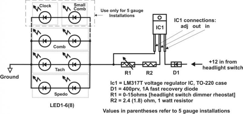 The way the regulator IC works is that its internal circuit tries to maintain the voltage of its “out” terminal 1.25 volts above that of its “adj” terminal by adjusting the impedance between the “in” and “out” terminals. The current that it will regulate to in the above circuit is then given by I = 1.25/(R1+R2). Variable resistor R1, the headlight switch rheostat, varies from 0-15ohms and then jumps to infinite ohms (open circuit) when the knob is rotated fully counter-clockwise. Resistor R2 is in the circuit to set the maximum current when R1 is at 0 ohms. When R1 is at infinite ohms, no current can flow from the “out” terminal to the LEDs, so they turn off, as one would expect. Actually, a small amount of current (~10ma) still flows from the “adj” terminal to the LEDs, lighting them very weakly. This doesn’t hurt anything, and normal operation is restored as soon as R1 is turned back to a finite resistance. At intermediate settings of R1, we can calculate the current from the above formula. From the current and the known voltage drop of the LEDs, we can calculate the power dissipated in each component. This lets us see what the maximum values are, and then to know what sort of power rating and/or heat sinking may be required. Shown below are some spreadsheet calculations like this for the cases of three and four strings of two LEDs each. 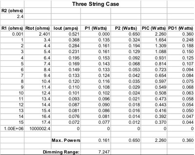 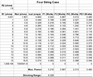 In each case, I’ve chosen R2 to give a maximum current through each LED of about 175ma. From the initial graph, you can see that this will produce about three times the light output of the standard 2 watt bulbs. As you rotate the headlight switch knob counter-clockwise, the intensity will dim down by either about seven or about nine times before going out completely at full CCW. The dimming range is equal to the ratio of the maximum to the non-zero minimum current, which is equal to (R1max+R2)/(R1min+R2). Since R1max = 15 and R1min = 0, this is (15+R2)/R2. Thus, the smaller R2, the larger the dimming range. The range for both these calculated cases is reasonably close to the stock range, hence probably acceptable for most of us. The calculated power dissipations for the regulator IC, R1, R2 and D1 are also shown. As you might expect, the maximum power dissipation for R2, D1 and the regulator occur at full brightness, while, since a zero ohm resistor can dissipate no power, that for R1 occurs at a somewhat lower brightness setting. A standard 1 watt resistor will work fine for R2, and the less than one-quarter watt requirement for R1 is substantially less than the power it was designed to handle originally. 400PRV fast recovery diodes rated at 1A are readily available, and will be more than adequate for D1. The roughly 3 watt dissipation in the regulator IC is no problem, but is enough to require a heat sink, and even with a heat sink the device will heat up to 130-140 deg F when used in normal warm ambient temperatures. In addition, there is a mounting problem with the regulator, since the metal tab that is the thermal path for heat removal is in electrical contact with the “in” terminal, i.e. the switched 12 volts, so it can’t directly touch anything that’s grounded to the body of the car. Probably the best solution is to mount the IC, R2, and D1 in a small metal box that can be clamped to the body somewhere. The box will then protect the circuitry against shorts and mechanical abuse, and will form a suitable heat-sink for the IC. There’s nothing special about the box I specified, other than that it’s the smallest standard size I could find. The regulator’s TO-220 package can be attached to the box with a mounting kit that provides a thermally conductive but electrically insulating pad to go between the IC’s tab and the mounting surface, as well as a screw/nut/flat washer/lock washer and insulating shoulder washer combination that allow clamping everything together without creating any shorts. The table below lists the items required to build the regulator circuit as described, together with their part numbers at Mouser Electronics (www.mouser.com), one of several electronic component suppliers from which such parts can be ordered on-line with a credit card and shipped to your door. The shipping charges for all the parts on this list will likely exceed the cost of the parts themselves. 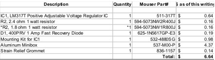 To mount the completed box as described herein, you will also need 2ea. #6 captive nuts such as PEM #KFS2-632, and 2ea. 6-32 x ½” screws, plus some scrap aluminum sheet, 1/16” or so thick Mouser doesn’t stock these hardware items, but local hardware stores are likely to have them. If you can’t find them elsewhere, McMaster-Carr (www.mcmaster.com) definitely has them. We use series strings of only two LEDs here because two is the number of lamps in each gauge, and two adapts well to the cases of both three and five gauge installations. You could use strings of three LEDs instead, if, for instance, you have a three gauge dash but want to also dim the three gauges in your center console, which would require nine LEDs (assuming each gauge in the console has only a single lamp). You would then hook them up as three strings of three LEDs each, and use the 2.4ohm value for R2, as in the three string/two LED case above. The regulator will work just as well with no other circuit changes. It will just drop less voltage across its internal pass transistor. You could also change the color and/or type of LED (as long as the LEDs used can run at the same current) without problem. The main requirement is that all parallel-connected serial strings have the same number (and similar type) of LEDs. If you violate this rule, the string with the smallest number of LEDs will get almost all the current, will light up enormously brighter than the others, and may heat up so much they burn out. A side benefit to using three LEDs /string is that the power dissipation in the regulator IC will drop to about a watt, which would make it feasible to use a clip-on anodized heat sink if you really wanted to avoid mounting the circuitry in a metal box. The ceramic package for these LEDs incorporates a metal pad that’s intended to provide a good thermal path to an external heat sink for the large amount of heat generated when these devices are operated at full rated current. We won’t need to run them nearly that hard to produce more light than the stock instrument bulbs, so the heat sinking isn’t necessary. The conventional lamps we want to replace are mounted in cylindrical plug-in sockets about 3/8” in diameter and an inch long. Since the entire LED package will easily fit within a 3/8” diameter circle, a simple way to make a package equivalent to the lamp sockets is to glue them to the ends of posts that are made the same general shape. The posts can be made of almost any material as long as the LEDs can be glued to it. The posts I made for this purpose were of aluminum, and are described by the drawing below: 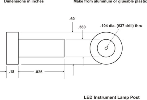 The larger diameter flange at one end is just to prevent them from being pushed too far into the sleeves that they fit in on the instrument cases and to provide a grip so they can be pulled out, and the hole down the center is to provide room for the wires to the LED contacts that need to be brought out to the back. I designed these parts to be the same size and shape as the conventional bulb holders they replace, however, the only important considerations are that the LEDs be held in close to the same position as the small light bulbs they’re replacing, that wires to both electrical contacts of the LEDs are brought out where they’re accessible, and that both contacts are kept electrically isolated from the instrument case and everything else that’s grounded. Once you have the posts, you can assemble the LED lamps as follows. 1. Solder wires to the LED contacts. This is the most difficult part of this project. The LEDs are designed to be surface-mounted on printed circuit boards, not hand-soldered, so their contact pads are quite small (~.025”x.050” with a .015” gap between them). Making good solder joints to these small pads requires a small soldering iron with a fine tip. The one I used looks like this: 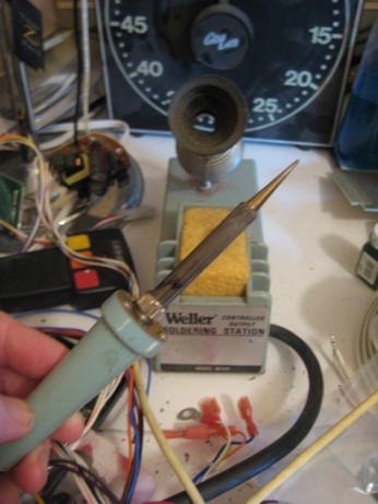 This iron has replaceable tips, and this tip measures .05” wide at the end, which was fine for soldering to these small pads. If you’re not familiar with electronic soldering, two important things to keep in mind when making connections of this kind are: use high (60% or more) tin (and not acid core) solder, and keep the tip of the iron clean by frequently wiping it against a damp sponge. A hole, drilled with a #37 drill in a small block of plastic (or something soft enough to not scratch the transparent plastic lens of the LED), can serve as an jig to hold the LED while soldering. Place the lens of the LED facing down into it, which will prevent the part from moving and will put the contact pads on the opposite side of the ceramic substrate from the lens on top where you can get at them. 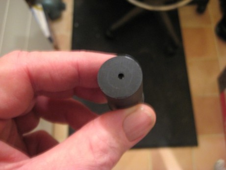 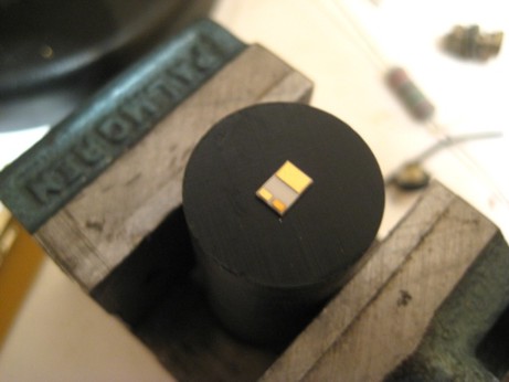 The finished lamps will have to be wired in series/parallel combinations later, so allow 12”-18” of wire at this stage for each contact. Small, flexible 28 gauge stranded wires are fine. Use different colors for the + and – terminals. Red for + and black or brown for – are good choices. Strip only 1/16” or so of insulation off of each wire on the end to be soldered. Tin (coat with solder by heating with the iron and melting on a small amount of solder) both the contact pads on the LED and the stripped ends of the wires before making the final connections. 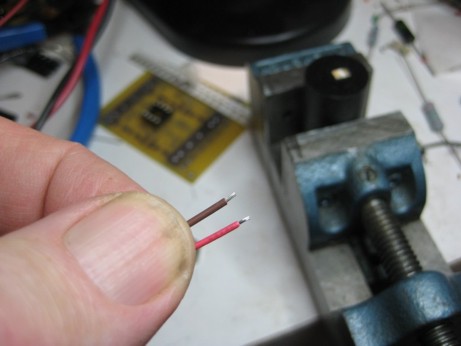 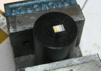 Lay the wires over the LED so that the tinned ends are over the contact pads with the wires themselves extending away from the edge nearest the pads. After tinning, the insulation of the wires may have shrunk back, exposing more conductor. If so, position the wire so that the insulation covers the larger thermal contact pad at the opposite end of the substrate. You can trim the excess conductor back even with the substrate edge afterward. (To be continued on the next post) |
   |

 
|
| Larry.Hubby |
Jan 28 2010, 11:03 PM
Post
#2
|
|
Member who doesn't post much, but has a long time in 914s Group: Members Posts: 188 Joined: 24-November 04 From: Palo Alto, CA Member No.: 3,172 Region Association: Northern California |
(Continued from last post)
 Solder the wires to the pads. You should need little or no extra solder. Just the tinning you’ve already put on the wires and pads should be enough. Test each joint for soundness by pulling gently on the wire. Successfully-soldered and trimmed parts should look like this: 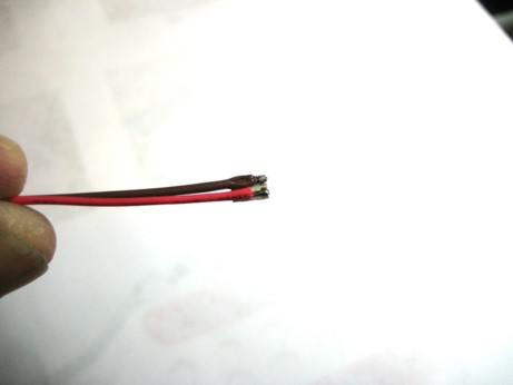 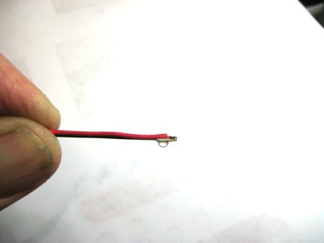 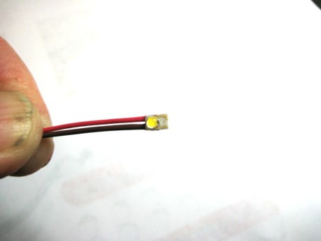 2. Test each one. Make sure all the assembled lamps light up by hooking them up briefly to a series-connected pair of standard batteries, or some other form of 3volt power supply that can deliver 200-300ma minimum. Fix any that don’t before going further. 3. Attach the LED and wires to the post. Using long-nose pliers to grip the wires only (not the fragile ceramic substrate of the LED), bend the wires up at 90° to the plane of the LED substrate at a point close to the location of the LED chip. 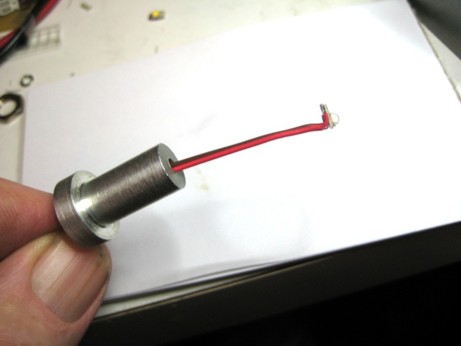 Then feed the wires down through the central hole in the post. Before pulling the LED down onto the end of the post, apply a glob of epoxy large enough to fill the volume between the back of the LED and the top of the post to one or the other. 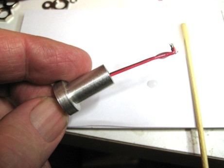 Apply slight tension to the wires that emerge from the bottom of the post to hold the LED against the post. Wipe off any excess glue that might get onto the outside diameter of the post with an acetone or MEK-soaked rag before it sets. Be careful to not get any glue or solvent on the clear acrylic window of the LED. Make sure the LED is reasonably centered atop the post while the glue sets. Quick-set 2-component clear epoxy (such as Hardman’s, which is available in single-use twin “bubble” packs) is a good choice for the glue, since it will hold securely even if the part heats up to more than 150 deg F, and is transparent when set so that the output light will not be obscured even if you get some of the glue on the LED’s window. It also sets in 3 minutes, which means that you need to be organized and ready to do all of the parts promptly, one after the other, unless you don’t mind mixing up and throwing away most of a lot of batches of glue. Getting a significant amount of epoxy down into the central hole for the wires is a good thing, as it will form a strain relief for the wires. 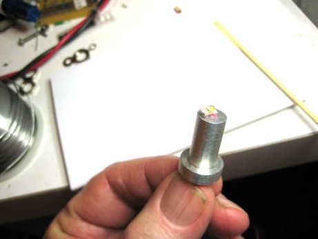 When you’re done gluing the parts, test them again, both to see if the LEDs still light up, and also check that neither of the contacts are shorted to the metal of the post (if you’ve used metal for the post material). I’ve had no problems with shorting, just using the epoxy with aluminum posts, but if you do, or you’re worried about it, you could always slip #4 or #6 fiber washers over the wires before feeding them down the hole in the post and gluing the entire thing down to the top of the post. Just make sure that the glue you’re using will adhere well to the fiber washers before you include them. Once you’ve done the lamps, you can assemble the regulator circuit. The circuit components that go in the box look like this: 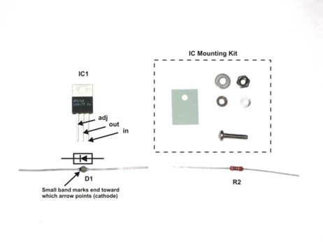 The circuit is so simple, there’s no need for a circuit board or even a terminal strip. R2 and D1 can simply be soldered directly to the leads of IC1, like this: 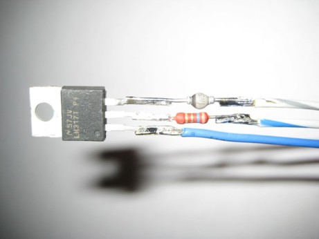 Attach ~18” long lengths of wire to the free ends of IC1’s “adj” terminal, R2, and D1, different colors for each so you can tell them apart after the box is assembled. You’ll trim these to length and crimp on terminals later, when you decide where you’re mounting the box. In the photo, you can see I used blue for “adj”, white/blue for “out”/R2, and white/gray for “in”/D1. I used 18 gauge wire, but anything larger than 24 gauge is fine. It’s good practice, but not absolutely necessary to also cover the exposed connections with heat shrink tubing, like this: 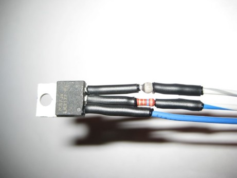 The box is made from two pieces that disassemble like this: 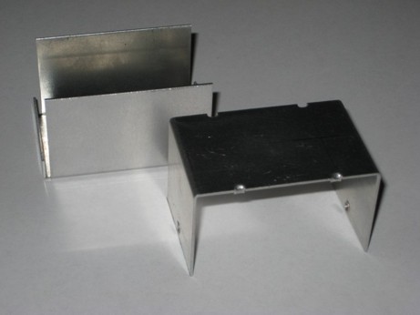 You have to drill only one hole to mount the components, and one hole to feed the wires through to the outside. If you mount the box the way I did, with a clamp that can grab the upturned edge of the steering column mounting bracket, you also need to drill two holes for some PEM nuts. The drawing below shows the locations and sizes of all these holes: 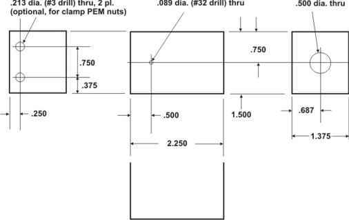 After you drill the holes, press in the PEM nuts if you’re using them, and assemble the components to the box by first feeding the wires through the large hole in one end. Bend the leads so that they form a smooth curve that allows the IC to sit in position flat against the bottom of the box and all of the solder joints/heat shrink tubing and other components to be inside the box, and yet avoids any sharp kinks where leads emerge from component packages. You can then mount the IC using the kit components by inserting the screw from the outside of the box, then placing on it, in order, on the inside of the box, the insulating pad, the regulator, the fiber shoulder washer with its reduced diameter fit into the hole in the regulator tab, and lastly the flat washer/lock washer/nut combination. Make sure the pad is aligned to prevent the regulator tab from touching the box anywhere, and tighten the screw down snug. No thermal compound or grease is required. Next, attach the strain relief grommet to the wires on the outside as close as you reasonably can to the box and snap it into the large mounting hole. If you haven’t used this kind of grommet before, just lay the wires into the channel in the larger part of the grommet with the larger end of the grommet away from the mounting hole. Then fold the smaller part of the grommet attached by the thin web over and engage its tab into the slot in the larger part. Next, take some sturdy pliers (curved jaw pliers work best) and squeeze the two halves of the grommet together, gripping both only on the large end so that they don’t hang over the notch into which the metal of the box is to fit, and push the tapered end of the grommet into the mounting hole. If the fit seems too tight, squeeze harder with the pliers. Once the grommet snaps into the hole, the resilience of the wires will push its two halves apart, locking it in place. Your assembled regulator will now look like this: 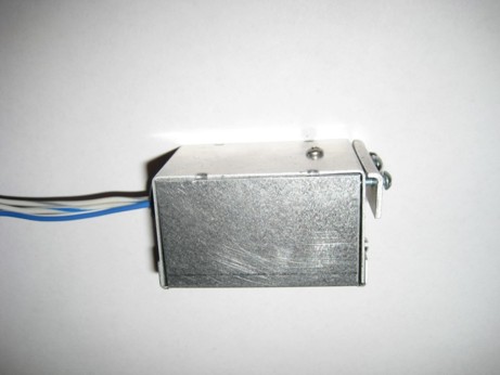 And you can re-assemble the two halves of the box and secure them together with the provided screws. It’s a good idea to hook the entire circuit up and test it out before installing it in the car. Pair up all the LEDs and hook the positive lead of one to the negative lead of the other in each pair, then hook all the remaining positives together and to the regulator, and all the remaining negatives together and to ground. It’s just as well to make a good, finished connection complete with tape or heat-shrink tubing insulation on the splice for the connection between the LED pairs, because you’ll just have to re-do them as soon as you verify the circuit’s operation if you don’t. Allow about 4”-5” of wire total between the two LEDs for pairs that are going to be used in the same instrument case. You can use the car battery as the voltage source. You don’t need a spare headlight switch to use for R1, but by all means use it if you have one. Otherwise, just hook the wire from R2 directly to the LEDs strings, which will run them at full current. Verify that all the LEDs light up, more or less to the same intensity, and that nothing gets dangerously hot after running for a few minutes (the regulator box will get fairly warm, but it shouldn’t get too hot to touch). If it all looks OK, you’re ready to install. (To be continued in next post) |
|
|
|
| Larry.Hubby |
Jan 28 2010, 11:12 PM
Post
#3
|
|
Member who doesn't post much, but has a long time in 914s Group: Members Posts: 188 Joined: 24-November 04 From: Palo Alto, CA Member No.: 3,172 Region Association: Northern California |
(Continued from last post)
You could just let the completed box lie loose in the area behind the gauges, since the box should provide sufficient heat sinking so that nothing will get too hot, or you could tie-wrap it to something. Personally, I hate the idea of loose components rattling around behind the dash, so I looked for a way to anchor the box securely to the body, but without drilling any holes. The arrangement I came up with is to clamp the box to the upturned edge of the steering column mounting bracket on the left side. If you remove the gauges, you can see this bracket directly behind and below the hole for the tachometer. The dash sheet metal is cut away in this area to clear the bottom of the gauges, and there is a volume below the gauges on either side between the bracket and the nearest control mounted to the front of the dash that is large enough to contain our regulator box without it having to touch anything else. To attach it without drilling any holes, I used the simple clamp shown in this drawing, which I made from some scrap 1/16” aluminum sheet: 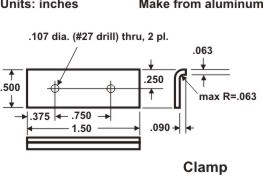 With this clamp, the ready-to-attach box looks like this:  The bracket in the car to which the clamp attaches is the one that holds the steering column. Here’s a photo of this bracket taken with the dash removed, so you can see it clearly: 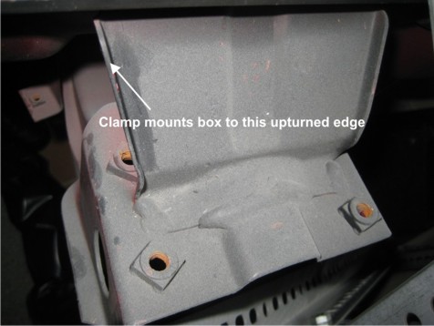 In the car, with everything but the instruments in place, it looks like this: 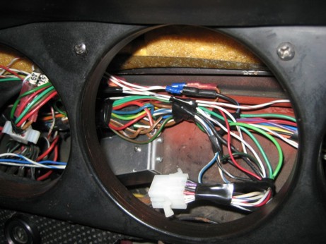 The final step is to complete the wiring. Hooking the LEDs up in pairs, installing each pair in an instrument (or splitting a pair between two single-lamp instruments in the case of the small gauges in a five-gauge dash), and connecting all the remaining + and – leads together to tie to the switched lamp power and ground, respectively, are straightforward and mostly things you’ve presumably already done to test the regulator. The only remaining part is installing the regulator in the switched lamp power line, which I’ll describe next. The headlight switch is the source of the switched lamp power and contains the rheostat we want to use for R1, so we need to pull it out where we can make connections to it. Disconnect the ground strap from the battery and remove the two screws, one on either side, that mount the fuse panel under the dash above the driver’s legs. Let the panel hang down, supported by the many wires connected to it. Remove the knob and mounting nut from the headlight switch in front of the dash, and pull the switch with its attached wires out the back of the dash and let it hang down in front of the fuse panel. The two wires from the regulator we have to hook up here are the “in” and “out/R2” wires, colored white/gray and white/blue in the photos, respectively. Run these two wires down with the wiring harness to the area near the switch. At this point, the headlight switch should look like this: 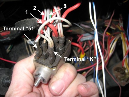 Terminal “K” receives power whenever the switch is pulled out to either notch, and is the source for the power to the instrument lights. Of the three wires attached to this terminal, all colored light gray, one (shown as #1 in the above photo) is a jumper to one of the two terminals at the extreme rear of the switch that are the connections for the rheostat. Unplug this wire from the terminal at the rear of the switch, cut the “in” wire to length, crimp a male tab connector on the cut wire, and plug the jumper wire onto the “in” wire to the regulator. Next, cut the “out/R2” wire to length, crimp on a female tab connector, and plug it onto the terminal at the rear of the switch from which you removed the jumper. The existing black/blue wire on the other rheostat terminal at the rear of the switch should be left in place. It runs up to the area behind the gauges, and ends in a connector into which a second connector plugs that has six black/blue wires that feed the existing instrument lamps. We’ll be unplugging and changing things at this connector a little later. At this point, your connections to the switch, which are now complete, should look like this: 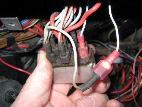 If, like me, you have an early car that pops up its headlights when the headlight switch is pulled out to the first notch, and have always wished it were not so, you can take this opportunity to fix that, since you already have the switch out and are actually looking at the offending wires. Looking back at this picture of the switch: The three numbered wires on terminal “K” are all power feeds for various things. #1 is the power source for the instrument bulbs, #2 is the wire that causes the headlights to pop up, and #3 feeds the optional fog lamp circuit. You can distinguish #2 from #3 by the diameter of the wire, #3 being slightly larger than #2. To correct the behavior of the pop-ups, we want to remove wire #2 from terminal “K” and hook it instead to terminal “51” on the opposite side at the front of the switch. Cut wire #2 as close as possible to the connector and crimp on a new female tab connector. Since there are already connections to terminal “51”, the easiest thing to do is use a “piggy-back” connector which provides a second male tab for the wire already on the terminal. If you can find them, there are crimp-on terminals with this feature, but there are also separate piggy-back adaptors, which is what I’ve used here. 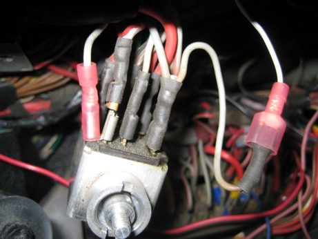 And, since these are hot terminals, I always like to insulate the exposed metal with heat-shrink tubing. 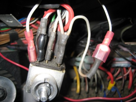 You’re now done with the headlight switch, so you can re-mount it to the dash and screw the fuse panel back to its mounting brackets. Don’t forget to re-connect the ground cable to the battery. The only remaining connection is that of the “adj” wire from the regulator box. To connect that, we return attention to the area behind the gauges, in particular to the connector at the end of the black/blue wire from the headlight switch that fed the original instrument lamps mentioned earlier. Presumably, you have already replaced the wires that plug into this connector with the three or four positive leads from the LED strings gathered together and crimped into a new mating tab connector. Likewise, you presumably have also already either gathered all the negative leads together and connected them to a suitable new ground connection, or grounded each negative lead to the case or ground connection of their associated instrument. Dress the “adj” wire to the location of the connector at the end of the black/blue wire from the headlight switch. Cut the wire to a convenient length to connect at this location, and also cut a short (~2”) length of the same wire from the excess that you cut off. Crimp both the “adj” wire and one end of this short piece into a male tab connector, and crimp a female tab connector onto the other end of the short piece. Remove whatever is plugged into the black/blue wire connector and replace it with the male connector of the two just installed on the “adj” wire. Plug the connector into which the positive leads of the LED strings have been crimped into the female connector on the other end of the short wire. When you’re done, the connections will look like this: 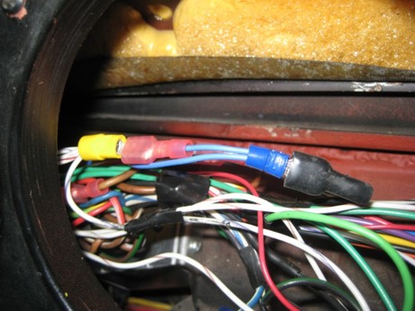 You should remove the original sub-harness of six illumination bulb sockets that are all wired to a single male connector. You could have added the “adj” wire to the gathered positive leads and crimped them all together into a single connector that would then plug into the one from the headlight switch, but the value of doing it this way with these extra connectors is that the regulator can then be removed completely and independently by simply unplugging things should that ever be necessary. It’s difficult to accurately capture the subjective appearance of something like the instrument illumination at night with a digital camera, but the image below of this system in place in my car isn’t too far off the mark. Unfortunately, the steering wheel blocks much of the outer two gauges in this view, but the illumination level is pretty close. 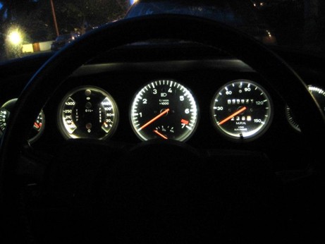 One final advantage to using this sort of LED is the ability to tailor the light distribution with a felt-tipped marker. You may have noticed that the instrument illumination is uniform with neither the stock bulbs, nor the LEDs as described thus far. This is because the mounting locations for the bulbs are much closer to some points along the edge of the instruments than others, resulting in illumination hot spots at these points. If you want to reduce or eliminate these hot spots, and are willing to play around with it, you can use a black felt-tipped pen to darken an area on the surface of the LED lens that’s nearest the corresponding hot spot. After doing this, you must take care to insert the LED in the correct orientation, so that the darkened area remains nearest the hot spot. Going back and forth a few times changing the darkened area should allow you to achieve an acceptable level of uniformity. If you darken the lens too much, you can wipe off the ink with a tissue or q-tip moistened with a gentle solvent like isopropyl alcohol. I don’t have an example photo of this to show you because I didn’t do it on my car. I’m anal, but not that anal. You may also find you want to increase the current to the LEDs to make up for the light loss due to this selective darkening, or you may simply want more light than the design parameters I’ve chosen deliver. If either is the case, you could increase the current through each LED to 350ma, which should double the light output, by reducing the value of R2 to 1.2 or .9ohms for the cases of three or four strings, respectively. In either case, R2 would need to be changed to a 2watt resistor. D1 would also need to be changed to a diode with a 2A or higher current rating. The regulator IC should still be OK, but its box will get warmer than before. The LEDs themselves will heat up about 11°C above the ambient temperature, rather than about 5.5°C with the design shown. So, unless you run your lights when the temperature inside the car is 54°C (129°F) or more, the glue that mounts them to the posts should still hold OK. This level of light is probably about the maximum these components can deliver, however. |
|
|
|
| Jeffs9146 |
Jan 28 2010, 11:33 PM
Post
#4
|
|
Ski Bum Group: Members Posts: 4,062 Joined: 10-January 03 From: Discovery Bay, Ca Member No.: 128 |
Patent Pending!!! (IMG:style_emoticons/default/sheeplove.gif) (IMG:style_emoticons/default/beer.gif) jk
|
|
|
|
| Mikey914 |
Jan 29 2010, 02:12 AM
Post
#5
|
|
The rubber man Group: Members Posts: 12,772 Joined: 27-December 04 From: Hillsboro, OR Member No.: 3,348 Region Association: None |
Larry, excelent job!
I had been providing LEDs to swap out with the std inst bayonet bulbs. They dim slightly, but this is by far best appication I've seen yet. Might I suggest you provide "kits" to expedite the installation. |
|
|
|
| aircooledtechguy |
Jan 29 2010, 11:32 AM
Post
#6
|
|
The Aircooledtech Guy Group: Members Posts: 1,966 Joined: 8-November 08 From: Anacortes, WA Member No.: 9,730 Region Association: Pacific Northwest |
QUOTE(Mikey914 @ Jan 29 2010, 12:12 AM)  Might I suggest you provide "kits" to expedite the installation. (IMG:style_emoticons/default/agree.gif) Larry for Prez!!! Excellent article!! Can this be fast-tracked to the Classics thread forum?? |
|
|
|
| championgt1 |
Jan 29 2010, 12:00 PM
Post
#7
|
|
Don't embarrass me Filmore! Group: Members Posts: 2,681 Joined: 3-January 07 From: Tacoma, Washington Member No.: 7,420 Region Association: Pacific Northwest |
(IMG:style_emoticons/default/agree.gif) Those gauges look great illuminated. Awesome!
|
|
|
|
| Cevan |
Jan 29 2010, 04:10 PM
Post
#8
|
|
Senior Member Group: Members Posts: 1,079 Joined: 11-December 06 From: Western Massachusetts Member No.: 7,351 |
Wow, that is one of the most detailed writeups I've ever seen. Great job. This is on my "to do" list.
|
|
|
|
| Brent |
Jan 29 2010, 04:24 PM
Post
#9
|
|
Every month is Oktober Group: Members Posts: 1,360 Joined: 16-December 04 From: North San Jose Member No.: 3,291 Region Association: Northern California |
Quality post! Brett and I both worked at HP OED division which merged with Lumileds.
|
|
|
|
| Dr Evil |
Jan 29 2010, 06:46 PM
Post
#10
|
|
Send me your transmission! Group: Members Posts: 23,041 Joined: 21-November 03 From: Loveland, OH 45140 Member No.: 1,372 Region Association: MidAtlantic Region |
I will be building one of these. Is it cheaper than buying the dimmer from Superbrightleds?
|
|
|
|
| edrotol |
Jan 29 2010, 08:27 PM
Post
#11
|
|
edrotol Group: Members Posts: 204 Joined: 23-April 06 From: Woburn, MA Member No.: 5,910 Region Association: North East States |
You betcha. I am one of those that know nothing about electronics at this level - yes I can do radios. etc, but not these stuff. Having said that. I also bet this would be a great seller if it were a "buy, plug and play" kit for those of us who are such, especially for those of us old enough to experience vision impairments - like, everything seems to be dim and not bright- you know the drill. the older you get the eys start going too, etc.. I kwow I would get at least 2 complete kits if they were available and two more if the apperance console lights were also made separately, but again price dependent. Great stuff and probably one of the best in a long time - with all due respect to those who have improved the breed. Kudos. |
 |
|
| Larry.Hubby |
Jan 30 2010, 10:01 PM
Post
#12
|
|
Member who doesn't post much, but has a long time in 914s Group: Members Posts: 188 Joined: 24-November 04 From: Palo Alto, CA Member No.: 3,172 Region Association: Northern California |
Thanks for the positive reviews, guys.
I'm not intending to offer any kits to do this, so I'd be fine with it if anyone else wanted to. The thing that would help more than anything else, as far as building sets of these lights is concerned, is some easier-to-mount LED package that's still less than 3/8" in diameter. This field (lighting-grade LEDs) is moving pretty fast, so something might come along soon. If I find anything suitable, I'll post an update. |
|
|
|
| Cevan |
Jan 30 2010, 10:05 PM
Post
#13
|
|
Senior Member Group: Members Posts: 1,079 Joined: 11-December 06 From: Western Massachusetts Member No.: 7,351 |
Did you fabricate the LED holders?
|
|
|
|
|
1 User(s) are reading this topic (1 Guests and 0 Anonymous Users)
0 Members:

|
Lo-Fi Version | Time is now: 30th June 2025 - 07:12 PM |
Invision Power Board
v9.1.4 © 2025 IPS, Inc.