|
|
|
Porsche, and the Porsche crest are registered trademarks of Dr. Ing. h.c. F. Porsche AG.
This site is not affiliated with Porsche in any way. Its only purpose is to provide an online forum for car enthusiasts. All other trademarks are property of their respective owners. |
|
|

  |

| pbanders |
 Feb 9 2010, 05:19 PM Feb 9 2010, 05:19 PM
Post
#21
|
|
Senior Member  Group: Members Posts: 988 Joined: 11-June 03 From: Scottsdale, AZ Member No.: 805 Region Association: Southwest Region |
Jeff's right, pure Cu is very soft. Ever hear of the Bronze Age? (IMG:style_emoticons/default/smile.gif) Think of Be as an improvement over Sn.
|
   |

 
|
| jk76.914 |
Feb 9 2010, 07:08 PM
Post
#22
|
|
Senior Member Group: Members Posts: 809 Joined: 12-April 05 From: Massachusetts Member No.: 3,925 Region Association: North East States |
The Niton XL-800 is also an X-ray fluroescence instrument. Here's an excerpt from a DOE test of the XL-800 dated April 2000:
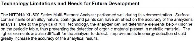 Note that chlorine is 17 on the periodic table!! That's higher than aluminum (13). AND BERYLLIUM IS 4!! The detection technology is called "proportional count". Newer technology is available now, using "silicon pin diode" detectors. As I understand it, the issue is signal-to-noise ratio. The lower atomic number elements may register, but their peak is lost in noise. The newer technology improves the SN ratio and they become visible. The Thermo-Fischer Scientific unit I tested my samples on (in November '08 BTW) using the newer technology can differentiate down to atomic number 12 (magnesium). There's yet a newer technology that can go lower, but it's moot for beryllium, because it's invisible to X-rays. So sorry to say, I think we both fell into the same pit. XRF is a fantastic technology, but it's blind to Be. ---------------------------------------------------------------------------------------- Meanwhile, back to the stainless steel idea. I ran some tests over the weekend on my copper and my stainless diaphrams (#1 and #4 in previous pics). I measured inductance vs. vacuum, but with the aneroid cells locked (filled with gorilla glue, clamped at nominal thickness during cure. Photo later tonight). I wanted to see the incremental effect of the enrichment diaphram alone. I had previously tested cells with the diaphram locked, and saw that they were amazingly linear from 0" to about 22", across several sets of cells of wide vintage, including the one stainless set. (post that chart later) So the two conditions were: first test, called SS- 1. outer screw set flush with bushing on cell side of diaphram (set before assembly) 2. inner screw set to an inductance of .85H at high vacuum (seated diaphram) 3. full load stop set to inductance of 1.00H at 0" vacuum. This setting maxes the bias of the diaphram towards the cells, with a total travel of 0.15H. (0.15H is kinda arbitrary, but not far off from Mr. Anders's 0.12H typical travel- I think. Can't find the reference in his MPS Bible at the moment, but I think it's 0.12H) second test, SS+ 1. inner screw set to inductance = 1.00 at 0", full load stop removed for this test 2. outer screw set to inductance = .85H at high vacuum (careful not to turn the inner screw while setting.) This biases the diaphram position away from the cells as far as possible, but still with the same 0.15H travel. The two curves represent the adjustment limits of the stainless steel diaphram. A picture's worth 10000 words: 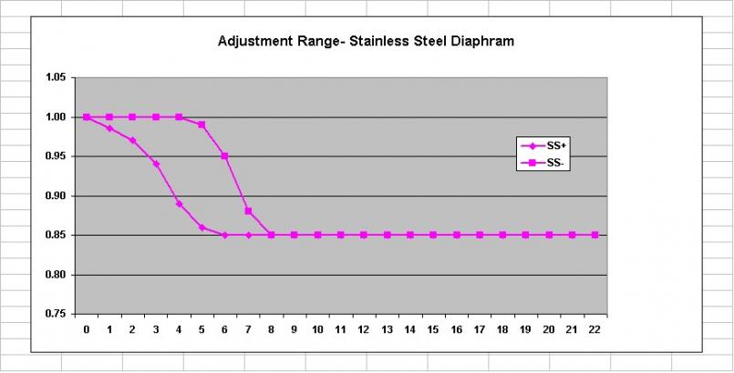 Comments 1. SS- curve looks like it blends smoothly with the 1.00 upper limit. It really doesn't. If I had the resolution to do 4.5" or even 4.25" it would crash abruptly into the limit. 2. That's quite a range, in both slope and vacuum at which the diaphram begins to lift off the stop. Quite an opportunity for careful tuning if you really got good at this. Oh, and here's the copper (diaphram #1, from the bottom of the lake) range.... I call it Cu-2P (copper- 2 pleat)- 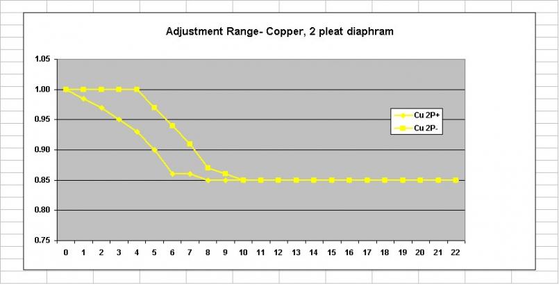 Note that in Cu-2P+ the diaphram starts to lift off the stop at 7", then stalls at 6", and then resumes a fairly smooth transition the rest of the way to 1.00H. I reran these points several times, and it repeated the same. I suspect that there is a point where the 2 pleat diaphram resists strain, which allows stress to build up, until it pops past that point and then behaves itself. This only occurs for Cu-2P+ because the entire test range for Cu-2P- is beyond this point. I still want to test the brass diaphram (#3 in picture). I may get a chance yet tonight, but I'll probably post the chart tomorrow.... Like I said, this is getting interesting! That's enough for now. I've got to drill some holes in my frozen lawn and put reflectors along my driveway. Big storm coming tomorrow. |
|
|
|
| Bleyseng |
Feb 9 2010, 07:20 PM
Post
#23
|
|
Aircooled Baby! Group: Members Posts: 13,036 Joined: 27-December 02 From: Seattle, Washington (for now) Member No.: 24 Region Association: Pacific Northwest |
yeah but, Eric's testing showed no Be just Al,bronze, etc in trace amounts. You tell me the alloy mix and I should be able to get it. He deals in airplane metals..
|
|
|
|
| jk76.914 |
Feb 11 2010, 04:59 AM
Post
#24
|
|
Senior Member Group: Members Posts: 809 Joined: 12-April 05 From: Massachusetts Member No.: 3,925 Region Association: North East States |
Quick update. I did the crappy brass characterization. Not surprisingly (I guess), it only had about 0.16H of total travel- when I set the outer screw flush with the bushing in diaphram on the cell side, and then set the inner screw to 0.85H at high vacuum (diaphram seated), I only had about 1.01H at 0". So basically there is no adjustment range the way I'm testing. This is almost certainly because of its stiffness. At least it has a pretty smooth transition.
In reality, assuming I need to get 0.12H of contribution out of the diaphram, there would be a little adjustment.... Anyway here's the curve-  Next step, I plotted a curve of a cell, without effect of diaphram. This was easy, I just snugged the full load stop down, pinning the diaphram between full load and idle stops. I've plotted a lot of cells (SS below), and they are almost perfectly coincident, cell to cell. But none tail up at high vacuum due to their expansion being limited by the limit arms?? Gotta figure this one out... 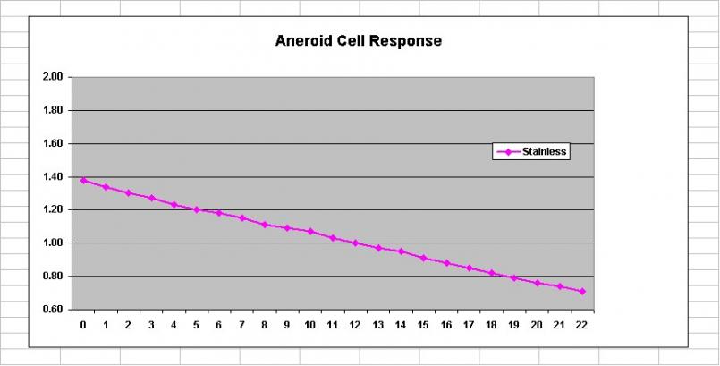 Note that my inductance meter is NOT calibrated to a known standard, so it may be different from one that any of you guys use. It's repeatable though, so for what I'm trying to do, it's working fine and was very reasonably priced. Gotta go to work. My last plots superimpose the cell curve and the diaphram curves. I'm looking for most range of adjustment and smooth transition for each diaphram type, and it's looking like the stainless one is going to be it. Of course, I don't have a stock copper w/ 3 pleats that isn't ruptured to test for comparison... I'll post those last plots tonight... Jim |
|
|
|
| jk76.914 |
Feb 20 2010, 11:43 AM
Post
#25
|
|
Senior Member Group: Members Posts: 809 Joined: 12-April 05 From: Massachusetts Member No.: 3,925 Region Association: North East States |
Yesterday during lunch, we tried to press apart a diaphram hub. One of the guys machined some custom blocking, and we set it up in a hydraulic press. Well, at 3500 pounds, it finally began to yield. Unfortunately, it was the hub that was yielding, not the presumed press-fit. (I used one of my crudely made brass aftermarket diaphrams.)
So we sectioned it. Take a look.... 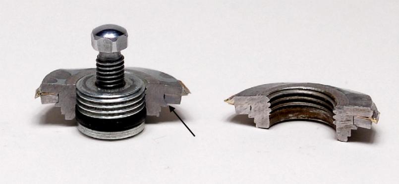 As you can see, there are three parts. The hub, the diaphram, and a locking ring. There is a ridge on the hub that retains the lock ring. The lock ring is continuous around the diameter of the hub, as is the ridge. All I can think of is that they chilled the hub/diaphram, heated the ring, and then assembled them. As they equalized in temperature, the ring tightened down on the diaphram due to the champher on the underside of the ridge on the hub (arrow). I determine the alloy next week using XRF, so I can figure out temperatures involved. Back of the envelope calculation says they needed a temperature difference of 5000 degrees or so to clear a 1/64" ridge if it's standard steel, which would have melted everything.... or else I need a new envelope. You can see the distortion in the hub from our attempts to press it apart. |
|
|
|
| underthetire |
Feb 20 2010, 12:39 PM
Post
#26
|
|
914 Guru Group: Members Posts: 5,062 Joined: 7-October 08 From: Brentwood Member No.: 9,623 Region Association: Northern California |
did the ring seem hard yet gummy when you cut it? A company I used to work for invented shape memory alloys, in fact even invented shrink tubing. The alloy was frozen in LN, then was stretched using a tapered arbor. Once it came up to temp, it would be back in it's original shape. These were and probably still are used on all the composite aircraft for the hydraulic systems. Guess if you have a hydraulic leak with a composite airframe, you get paper mache.
Very cool testing your doing BTW. |
|
|
|
| ArtechnikA |
Feb 20 2010, 02:16 PM
Post
#27
|
|
rich herzog Group: Members Posts: 7,390 Joined: 4-April 03 From: Salted Roads, PA Member No.: 513 Region Association: None |
QUOTE(jk76.914 @ Feb 20 2010, 12:43 PM)  So we sectioned it. Take a look.... As you can see, there are three parts. The hub, the diaphram, and a locking ring. There is a ridge on the hub that retains the lock ring. The lock ring is continuous around the diameter of the hub, as is the ridge. All I can think of is that they chilled the hub/diaphram, heated the ring, and then assembled them. To my untrained eye it appears that the flange of the hub that retains the lock ring might have been swaged in place. This technique would have been in keeping with mass-production (i.e. low-cost) quantities and readily available with late-'60's tooling. Memory-effect metals and cryogenic techniques were known then, but were considered 'aerospace-level' technology - not economy-car stuff... |
|
|
|
| Katmanken |
Feb 20 2010, 05:19 PM
Post
#28
|
|
You haven't seen me if anybody asks... Group: Members Posts: 4,738 Joined: 14-June 03 From: USA Member No.: 819 Region Association: Upper MidWest |
I think yer making this too hard.
I agree with the swaging technique. Smack a really hard fastener into a soft material with the right tools and I gurantee the soft material will flow in place. I've used a nut type fastener called a Pem Nut since the 70's. You drill a precision hole in aluminum, insert the Pem Nut and smack the crap out of it with a BF hammer. It swages the aluminum into the recess in the nut and holds everything in place. While not identical, the 914 part might use a similar technique with a Euro fastener. Pem works on mild steel if the steel is softer than the Pem fastener. Pems come in nuts, studs, etc, Attached are two pics of one type of a flush mount nut. One is shown inserted, and the second pic shows the optional swaging tooling... We used the BFH technique or with some types, used the screw to pull the nut into place. Pems might work for a new diaphragm. Attached image(s) 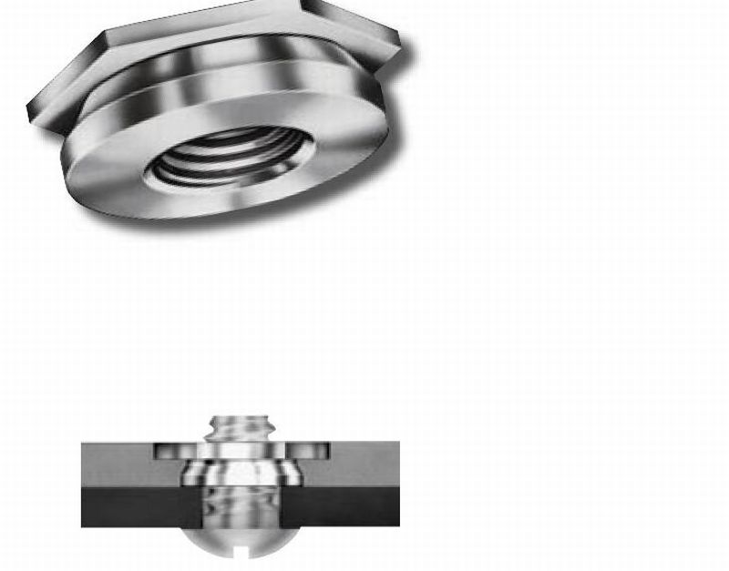 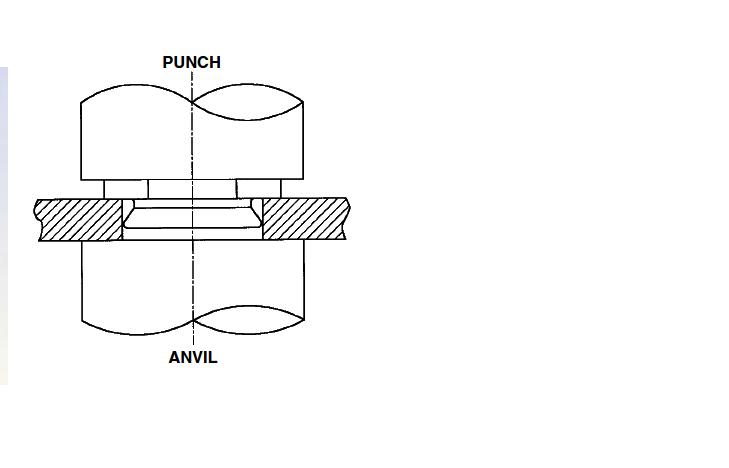
|
|
|
|
| 76-914 |
Feb 20 2010, 06:58 PM
Post
#29
|
|
Repeat Offender & Resident Subaru Antagonist Group: Members Posts: 13,866 Joined: 23-January 09 From: Temecula, CA Member No.: 9,964 Region Association: Southern California |
Great stuff here. I'll bet ya'll will have it figured out in no time. (IMG:style_emoticons/default/popcorn[1].gif)
|
|
|
|
| jk76.914 |
Feb 21 2010, 07:43 AM
Post
#30
|
|
Senior Member Group: Members Posts: 809 Joined: 12-April 05 From: Massachusetts Member No.: 3,925 Region Association: North East States |
QUOTE(kwales @ Feb 20 2010, 06:19 PM) I think yer making this too hard. I agree with the swaging technique. Smack a really hard fastener into a soft material with the right tools and I gurantee the soft material will flow in place. I've used a nut type fastener called a Pem Nut since the 70's. You drill a precision hole in aluminum, insert the Pem Nut and smack the crap out of it with a BF hammer. It swages the aluminum into the recess in the nut and holds everything in place. While not identical, the 914 part might use a similar technique with a Euro fastener. Pem works on mild steel if the steel is softer than the Pem fastener. Pems come in nuts, studs, etc, Attached are two pics of one type of a flush mount nut. One is shown inserted, and the second pic shows the optional swaging tooling... We used the BFH technique or with some types, used the screw to pull the nut into place. Pems might work for a new diaphragm. That's a great idea. I've also used PEMs. I'll be checking the material alloys this week at work, maybe tomorrow, and if the ring is softer than the hug, this is probably how they did it. Of course, for a repro, this could be how to do it regardless. |
|
|
|
| pbanders |
Feb 21 2010, 09:23 AM
Post
#31
|
|
Senior Member Group: Members Posts: 988 Joined: 11-June 03 From: Scottsdale, AZ Member No.: 805 Region Association: Southwest Region |
Great stuff, a few comments. One, the design of the adjustment flange is rather complex. Not only do you need it to be retained in the diaphragm, but you also need to supply a precise, smooth recess where the O-ring seal on the outer screw can slide, and maintain vacuum integrity during adjustment. From reviewing the Bosch patents, I can see that early on they tried to make "fixed" flanges without the outer screw adjuster, but apparently they found too much variation in the settings.
One more thing is that a low-effort way of getting what we want might be to work directly with a rebuilder, who has already done the tooling for the flange and the mounting process. Getting them to adopt a different diaphram material or design that gives better characteristics would be in their interests, and they could have a new market in selling diaphragms for something like $50 a pop. I think SLITS knows who picked up all of the stuff from Bret when they sold the business. |
|
|
|
| Katmanken |
Feb 21 2010, 12:05 PM
Post
#32
|
|
You haven't seen me if anybody asks... Group: Members Posts: 4,738 Joined: 14-June 03 From: USA Member No.: 819 Region Association: Upper MidWest |
I think they make the PEM's out of the stuff that they use for the hinges of hell.
No matter how hard they are hit, the other stuff deforms- not the PEM. Looks like the factory design is a sandwitch of a hard PEM like fastener, the soft diaphragm placed onto the fastener, and a steel or aluminum washer that captures the diaphragm on the fastener. The washer does the deforming. The particular one that I added above is a flush mount fastener and might require a sandwitch of a washer, the diaphragm, and a second washer on the other side of the diaphragm. That way, the soft diaphragm is pinched between the washers, and the washers do the deforming- not the diaphragm. |
|
|
|
| McMark |
Feb 21 2010, 12:09 PM
Post
#33
|
|
914 Freak! Group: Retired Admin Posts: 20,180 Joined: 13-March 03 From: Grand Rapids, MI Member No.: 419 Region Association: None |
You guys are awesome for researching this... (IMG:style_emoticons/default/smiley_notworthy.gif)
|
|
|
|
| jk76.914 |
Feb 21 2010, 12:13 PM
Post
#34
|
|
Senior Member Group: Members Posts: 809 Joined: 12-April 05 From: Massachusetts Member No.: 3,925 Region Association: North East States |
QUOTE(pbanders @ Feb 21 2010, 10:23 AM) Great stuff, a few comments. One, the design of the adjustment flange is rather complex. Not only do you need it to be retained in the diaphragm, but you also need to supply a precise, smooth recess where the O-ring seal on the outer screw can slide, and maintain vacuum integrity during adjustment. From reviewing the Bosch patents, I can see that early on they tried to make "fixed" flanges without the outer screw adjuster, but apparently they found too much variation in the settings. One more thing is that a low-effort way of getting what we want might be to work directly with a rebuilder, who has already done the tooling for the flange and the mounting process. Getting them to adopt a different diaphram material or design that gives better characteristics would be in their interests, and they could have a new market in selling diaphragms for something like $50 a pop. I think SLITS knows who picked up all of the stuff from Bret when they sold the business. Diaphram #3 in my original post is from a fresh Bret rebuild. It's the one I call "crappy brass", and it has no adjustment range, because it's so stiff. Their approach to mounting the diaphram maybe isn't so bad though. They cut the original diaphram back to where it's just a collar, and then soldered the replacement (with its oversize ID) onto the remnant of the original copper one. Quick and dirty, not very esthetically pleasing maybe, but maybe workable. It may work with a quality diaphram as well. I have to photo the other side of my stainless diaphram and post it. I think it's assembled differently.... Later today.... |
|
|
|
| jk76.914 |
Feb 21 2010, 01:49 PM
Post
#35
|
|
Senior Member Group: Members Posts: 809 Joined: 12-April 05 From: Massachusetts Member No.: 3,925 Region Association: North East States |
OK. I took some more photos. These three are copper, stainless, copper. (presumably beryllium-copper).
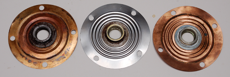 Both copper use the same hub attachment design- the one I sectioned earlier. The stainless one is different. It is definitely swaged together (arrows) in 6 places. 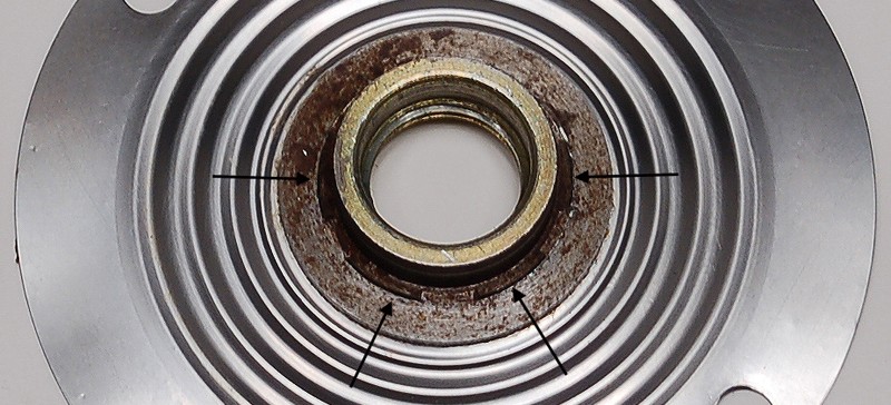 Could it be possible that the 2-pleat copper type was a factory attempt at addressing the fatigue problem? Now I'm more strongly doubting the stainless being factory, because both the material and the hub design are different. Of course, if Bosch put engineering into design improvements, they wouldn't have necessarily stopped at diaphram material. And the stainless hub has another difference- it protrudes higher off the diaphram on the ambient side. This allows for more adjustment before the outer screw's o-ring exits the hub and starts leaking..... Also, I peeled the lock ring off one section of the hub, and both the lock ring and the hub are definitely steel- they're magnetic. I'll find out what alloy later this week. 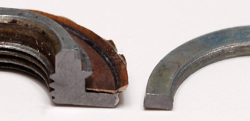 |
|
|
|
| jk76.914 |
Feb 27 2010, 04:57 PM
Post
#36
|
|
Senior Member Group: Members Posts: 809 Joined: 12-April 05 From: Massachusetts Member No.: 3,925 Region Association: North East States |
Picked up a -010 MPS this week, allegedly from a Volvo 142E, circa 1972. But it's got to be late 60s vintage, so I'm thinking it's probably from a P1800.
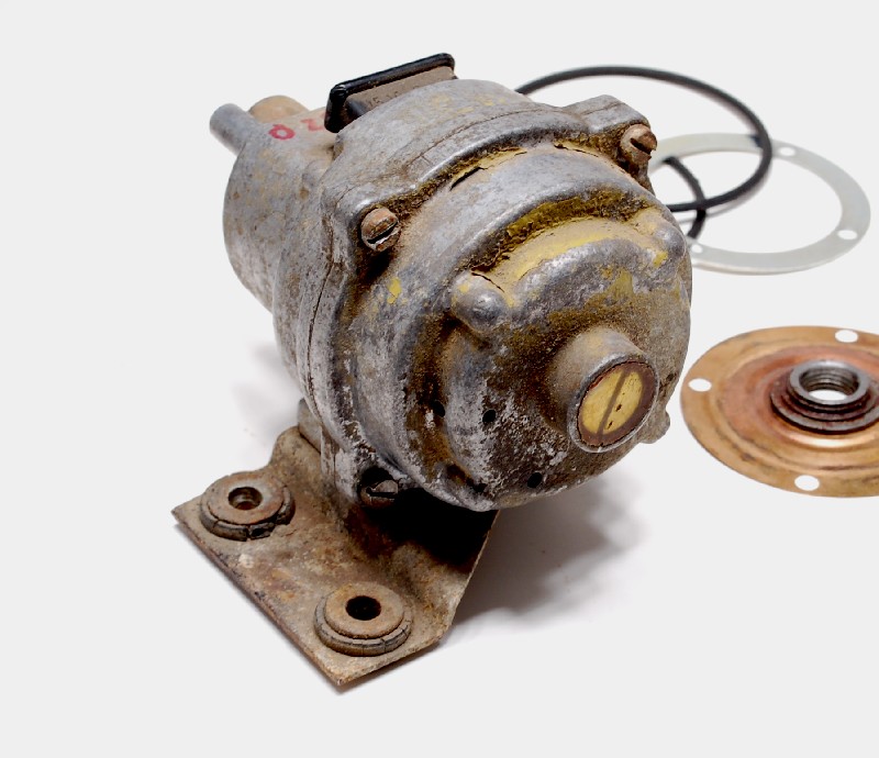 It's a long nose. These guys have a mechanical damper built into the snout, inside of the spring, which requires a longer snout to account for the extra piece. I'll post a photo later. Also, note that there are four drilled holes in the diaphram end, instead of cast slots like every other one I've ever seen. Kinda hard to see in the photo. Two are visible at about 3 o'clock, one on the face and one on the side. The other two are maybe 45 degrees below that. I profiled it, and then took it apart. It's a rebuilt, non-leaker, and sports yet a 5th diaphram type. The diaphram hub is idential to stock, which I'm now convinced is swaged as suggested by kwales. Anyway, the diaphram is a copper alloy, and it has 3 pleats, but the pleats range in width from wide on the outside to narrow near the hub. I've dubbed this the "3 asymmetrical pleat" diaphram, and she's a beauty!! 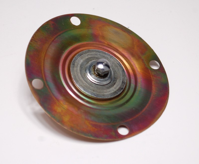 I loaded the diaphram up into my test MPS, with its filled aneroid- 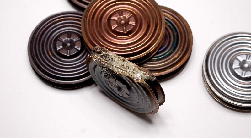 and profiled its adjustment range- 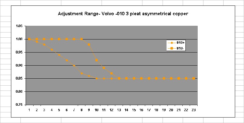 This is the widest adjustment range I've found yet. It beats out the stainless one, though not by much. In case anyone is wondering what I'm going to do with this, well, first I want to see which diaphram material/design has the greatest adjustment range, and then I'm intend to try my own materials and see what I can come up with that is comparable, or better than stock. I'll make a die set to press diaphrams from, and I've reverse-engineered a hub that will close with a lock nut so I can try different materials. On that note- I also picked up a -035 MPS- another Volvo, this one probably truly is from a 142E. It's short-nosed, original-riveted, and it doesn't leak. Tomorrow, I'm actually going to open it up (not for the squeemish, opening a non-leaking stock MPS!!!) so I can profile the stock copper diaphram to compare with all of these alternate designs. |
|
|
|
| McMark |
Feb 27 2010, 11:43 PM
Post
#37
|
|
914 Freak! Group: Retired Admin Posts: 20,180 Joined: 13-March 03 From: Grand Rapids, MI Member No.: 419 Region Association: None |
|
|
|
|
| rick 918-S |
Feb 28 2010, 12:23 AM
Post
#38
|
|
Hey nice rack! -Celette Group: Members Posts: 21,214 Joined: 30-December 02 From: Now in Superior WI Member No.: 43 Region Association: Northstar Region |
Love this science stuff!
|
|
|
|
| ArtechnikA |
Feb 28 2010, 05:16 AM
Post
#39
|
|
rich herzog Group: Members Posts: 7,390 Joined: 4-April 03 From: Salted Roads, PA Member No.: 513 Region Association: None |
QUOTE(jk76.914 @ Feb 27 2010, 05:57 PM) The diaphram hub is idential to stock, which I'm now convinced is swaged as suggested by kwales. ...or someone ... |
|
|
|
| 914Sixer |
Feb 28 2010, 07:35 AM
Post
#40
|
|
914 Guru Group: Members Posts: 9,429 Joined: 17-January 05 From: San Angelo Texas Member No.: 3,457 Region Association: Southwest Region |
Really amazing reading!! (IMG:style_emoticons/default/piratenanner.gif)
|
|
|
|
|
1 User(s) are reading this topic (1 Guests and 0 Anonymous Users)
0 Members:

|
Lo-Fi Version | Time is now: 4th March 2026 - 09:05 PM |
Invision Power Board
v9.1.4 © 2026 IPS, Inc.