|
|
|
Porsche, and the Porsche crest are registered trademarks of Dr. Ing. h.c. F. Porsche AG.
This site is not affiliated with Porsche in any way. Its only purpose is to provide an online forum for car enthusiasts. All other trademarks are property of their respective owners. |
|
|

Posts in this area are restricted to the following format. If you have a general question, please post it in the Garage.
1. All new threads MUST be titled with a part number only. (i.e. 901.351.801.17)
2. Thread description should be an english description of the part. (i.e. Brake Dust Shields)
3. Replies to the thread are only restricted by pertinence. Some examples are original finish of the part (painted, cad plated, etc), common failures (cracking at the mount points), repair information or tips, pictures (stock or custom), upgrades, etc.
If you have any questions regarding the rules of this forum, please PM McMark.

| McMark |
 Apr 2 2010, 10:40 PM Apr 2 2010, 10:40 PM
Post
#1
|
|
914 Freak!  Group: Retired Admin Posts: 20,179 Joined: 13-March 03 From: Grand Rapids, MI Member No.: 419 Region Association: None |
This is the electric sender that tells the gas gauge how much fuel is left in the tank. It has three electrical connections on top.
PET Illustration 905-03, item #27. Construction / Installation The visible portion is a stamped steel ring which was originally plated with clear zinc. The part number is stamped into this ring, as well as what appears to be the date of production. The electronics are captivated in a white plastic (nylon?) housing. The connection labels are molded into this housing. There is a blue stamp with a couple number, one of which appears to be date of production (the pictured sender says 1.73, Jan 1973, which matches the car it came from). The steel ring is attached to the plastic body by three pins of plastic which protrude through holes in the ring. The plastic pins were then melted to enlarge them, thereby trapping the ring. The five attaching bolts (N 010.207.6) and washers (N 011.556.2) were originally cad plated or yellow zinc plated. The sender seals against the tank with a rubber or cork gasket (477.919.133). Function -||| is the ground connection. G is the level connection. W is the warning light connection. The W connection grounds to 0 ohms when the black float reaches the bottom of its travel. The G connection ranges from ~0 ohms when the tank is full to ~70 ohms when the tank is empty. Troubleshooting / Repair The float will often get stuck along its travel. Sometimes it won't go lower than a certain amount. Something it won't go above a certain amount. Sometimes it won't move at all. The sender can be disassembled and carefully cleaned, which will sometimes restore proper function. If you flip the sender over, you should hear the float slide from one end to the other without sticking or stuttering. If the float does not move smoothly, proceed to disassembly and cleaning. If you attach an ohm meter between the -||| and W connections, you should read ~0 ohms when the float is right side up, and an open circuit when the sender is upside down. If you read these values, proceed to disassembly and cleaning. If you attach an ohm meter between the -||| and G connections, you should read ~70 ohms when the sender is right side up, and ~0 ohms when the sender is upside down. The resistance value should vary linearly as the float slides up and down. If you get irregular readings, proceed to disassembly and cleaning. Disassembly / Cleaning The sender has a small nut on the bottom. The nut is captivated by a small locking ring. Carefully bend the locking ring out of the way and then unscrew the nut with a 5.5mm socket. Set the nut and locking ring aside carefully. The plastic bottom cap just slides off the shaft. Then just pull the aluminum tube straight off, being careful off the delicate wires inside. Once the sender is apart you must be very careful. Braking the very thin wires will render the sender useless and you'll have to find a replacement. If the float is sticking, clean the center shaft with steel wool or sandpaper, depending on the level of corrosion. When you flip the sender, the float should slide from one end to the other smoothly and easily without interference. The following is not necessary, unless you want to do everything or you have erroneous resistance readings. Carefully clean the thinner, non-copper wires with super fine steel wool. Carefully clean the two small 'nubs' at the bottom of the sender with super fine steel wool. These are the EMPTY warning light contacts. Carefully clean the thin copper washer on the bottom of the black float with super fine steel wool. If you're extra extra careful, you can clean the four 'fingers' that press against the thin wires with a razor blade. Replace the aluminum tube, slide the bottom cap into place, place the locking ring over the threaded shaft (make sure to get the tab down in the small hole). Reinstall the small nut only finger tight. Overtightening can damage the sender. Carefully bend the locking ring against the nut in two places on opposite sides. Attached image(s) 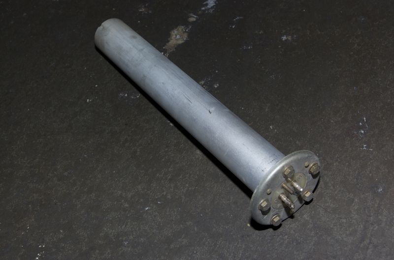 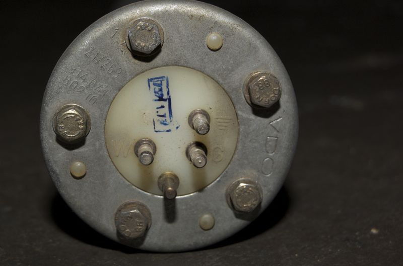 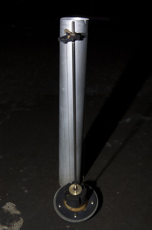 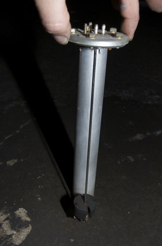 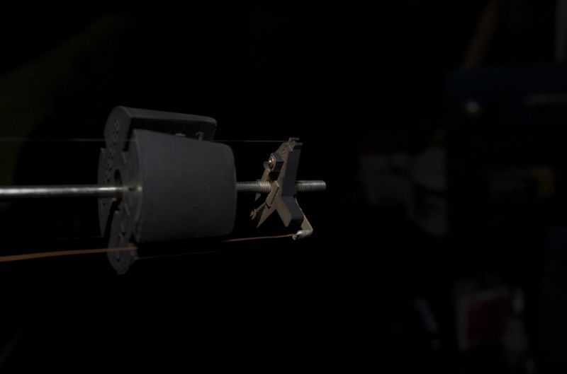 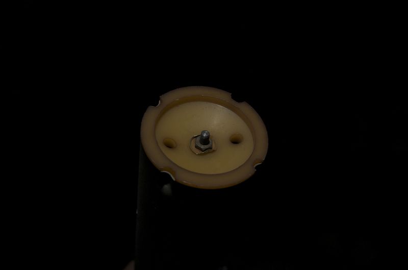 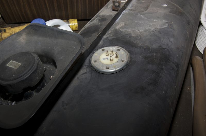
|
   |

 
|
Posts in this topic

  |
1 User(s) are reading this topic (1 Guests and 0 Anonymous Users)
0 Members:

|
Lo-Fi Version | Time is now: 17th May 2024 - 09:39 AM |
Invision Power Board
v9.1.4 © 2024 IPS, Inc.