|
|
|
Porsche, and the Porsche crest are registered trademarks of Dr. Ing. h.c. F. Porsche AG.
This site is not affiliated with Porsche in any way. Its only purpose is to provide an online forum for car enthusiasts. All other trademarks are property of their respective owners. |
|
|


| Larry.Hubby |
 Nov 29 2010, 10:26 PM Nov 29 2010, 10:26 PM
Post
#1
|
|
Member who doesn't post much, but has a long time in 914s  Group: Members Posts: 186 Joined: 24-November 04 From: Palo Alto, CA Member No.: 3,172 Region Association: Northern California |
My first encounter with bump steer came in 1971. I was 26, my car was about a year old, and I, like so many early owners, had gotten tired quickly of the tipi-toy handling that you got with the original suspension configuration. I had already replaced the 155SR 15 tires on 4.5” rims that the car was delivered with, added a factory front sway bar with the help of a friendly PCA member that had a 914 himself, and ditched the original shocks in favor of Konis. I had also scheduled a trip down to LA to buy some of the few aftermarket 914 suspension parts available at the time from Richie Ginther Racing in Culver City.
As I picked up the 22mm torsion bars and 180 lb/in springs that I had ordered, the Ginther parts guy said, “Do you want the rack spacers too?” “What do those do?” I asked. “They take out the bump steer,” he replied. Hmmm. Oh well, why not? They’re only $3.25 each (1971, remember). “Sure!” I say, and they go into the box along with the other parts. Later, on the way back up US101 to the Bay Area, I started chewing on the parts guy’s remark, which had left me feeling vaguely unsettled at the time. Why, I asked myself, would Porsche, who builds cars for knowledgeable enthusiast drivers, and who had at least a semi-clean sheet of paper in front of them when they started (OK, they used the front suspension pieces from the 911, but that’s supposed to be a higher performance model and shouldn’t compromise the design), design something that needed to be corrected, and is fairly easy to correct ($3.25 or even $6.50 can’t do much, even in 1971), into a production car? Maybe Porsche put it in intentionally. So, is it actually going to be dangerous to take it out, in which case why didn’t the Ginther guy warn me? Oh well, perhaps I’ll find out when I go to install those 5/8” thick spacers. Back home, it turns out to be a huge hassle to install the rack spacers because the rack can’t be raised 5/8” without hitting the top of the large central hole in the floor pan that the steering shaft enters through. I wind up grinding off about 3/8” of the sheet metal around the top of the hole to get enough clearance to mount the spacers. On the phone the next day, the Ginther guys claim they’ve never had to do that on a six cylinder car, but have never even tried it on a four. If actually true and due to a real design difference, this could be one of the most esoteric differences between the fours and sixes (I don’t see how it could be, however. PET shows the part numbers for both the steering rack and the front body floor as the same for the 4’s and 6’s). What a pain, but at least now I have immunity to tow changes when I raise or lower my ride height, right? Fast forward to now. I’m 65, the car is 40, is a converted 3.0 six, and now wears 205/50 and 225/50 tires on 7” and 8” rims. The ride height is 2.25” lower than stock, and has been for over 25 of those 40 years. I still run the Ginther torsion bars, springs, and rack spacers, and the car has been aligned many times. Being a card-carrying old fart now, I’m getting tired of wrestling those fat tires at slow speeds in parking lots, and seriously want to install power steering. I even bought a used VW Corrado PS rack on eBay to start the project. The first thing I did when it arrived was measure the distance between the inner tie rod joints and compare it to the spec for the factory 914 rack. It turns out to be 40mm larger than the stock 914 dimension. Hmmmm, won’t that cause…bump steer? All right, time to understand this bump steer thing. Since I did lots of computer simulations at work before I retired, I thought I would just write out the equations, measure the car, and calculate what happens. Then I thought that someone somewhere must have already written a program that can do this, and that you can download for free. It turns out several people have done this, but all of them that I found want a few hundred dollars to download and use their programs. I did find one, named Suspension Analyzer (available here: http://performancetrends.com/download.htm#drp), that allows you to download the program and use it for free for a ten-day trial period. Hmmmm, again. If armed with all the necessary data, a person could do quite a bit of analysis in ten days, particularly if all he wanted to do was find out how much bump steer he has and what he has to do to get rid of it. So, I spend a half-day under the front end of the car with a tape measure and a machinist’s square to locate the points shown below: 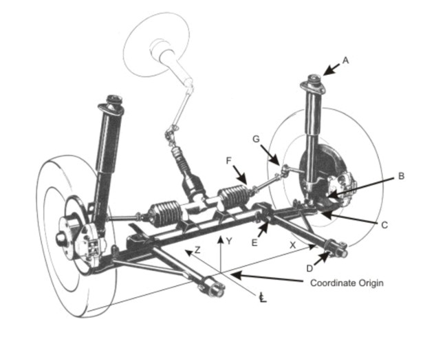 The way the program works is very straightforward. It has a pre-defined mode for strut front suspensions, and uses the coordinate system shown in the figure, which has its origin on the center line of the car at the fore and aft location of the line that joins the two centers of the front tire contact patches. The coordinate, x, is entered as positive for both right and left suspension elements. That is, no negative x-values are used, so the program essentially uses a right-hand coordinate system for the right wheel, and a left-hand one for the left wheel. I simply invoked symmetry, so that the same values were entered for both wheels. You don’t have to do this, the program will allow you to enter unique data for each wheel, front and rear (if you buy the full program, the demo version will do only the front), and will then calculate what happens for the whole car. My goals were more modest, so I only measured one front wheel and entered that data for both. One quirk the program has is that it requires the point, B, shown above, which it calls the “bottom of the McPherson strut”. The quirky thing is that B cannot be co-incident with C, which it calls the “lower ball joint”. If it is, some equation apparently becomes singular, and the program gives up and refuses to calculate or graph anything. Just what point B is supposed to be, and why they need it in addition to C, isn’t well-explained in the program manual, but, playing around with the program for a few days, I found that everything works as it should so long as the line joining points A and C passes through both point B and the line joining the centers of the two front tires when the wheels are pointed straight ahead (Z = 0 and Y = the rolling radius of the front tire). An error I was making initially is placing point C at Z = 0. C cannot be at Z = 0 because of the finite castor angle, as you can see from this drawing: 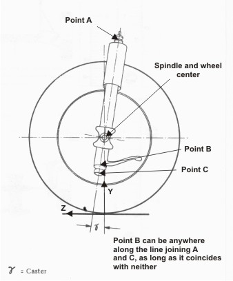 As I said already, B needs to be on the line that joins A and C. If it isn’t, the program will interpret that as misalignment between the strut and the spindle. In particular, if B is off even a small amount in Z, the program will interpret that error as a static toe angle that’s built into the strut and has nothing to do with the entered nominal toe-in for the front wheels or with any steering input. This sensitivity to the z-coordinate is the reason I’ve specified some of the locations on calculated points in the data below to so many decimal places. If point B is correctly on the strut axis, a wide range of locations for B all seem to give the same results (presumably, B needs to be far enough from A for the two not to run into each other at maximum strut compression). However, it’s tempting to still set B as close to C as possible because the graphics the program draws then look the most like they should. I wound up using a point 1” in y above C. The values shown in the table below should work if punched into the program. I measured the locations of all the other points shown in the figure on my car, and then calculated what they would have been on a stock 914, based on the known difference in ride height, tire size, and camber angle (a car lowered as much as mine cannot be brought back to the nominal camber setting without modification because of limited range of adjustment at the top of the front shocks). In each case I adjusted the location in x and z of point A to get the nominal camber (0° for stock, -1° for my car) and castor (6°) values, just as you would if you were actually aligning the car. And, of course, every time you change point A you have to change both B and C as well in order to keep all three of them on the correct straight line. The values I came up with for all the relevant points are as follows: 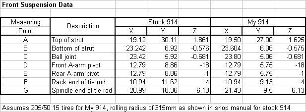 Note that the y values for points D and E are different between the two cases by more than the 2.25” in ride height that I quoted. This is because .86” of this difference is due to the difference in tire size. Plugging these into the program, I could calculate the amount of steering produced by deflecting the suspension vertically while the wheels are nominally pointed straight ahead, which is to say, the amount of the bump steer. The following graph shows the results for the various cases I was interested in: 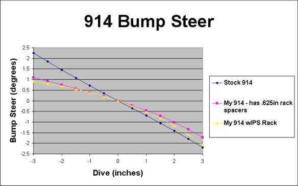 Dive is what the program calls y-axis deflection of the car body, rather than the suspension. So, positive dive is downward deflection of the body, but upward deflection of the wheels relative to the body. The bump steer is calculated in degrees, and positive bump steer corresponds to toe-in. So, we can see several things immediately. The stock 914 does indeed have lots of bump steer, more than 2° over the full 3” of suspension travel. I found this result surprisingly large, but I checked my measurements several times and I presume at this point that they are close to right. My lowered 914 with the Ginther rack spacers does have less, although not a lot less, and the difference is mainly at negative dive, when the wheels are unloaded. And here, I’ve been assuming for nearly 40 years that I had none! Probably, the much firmer suspension provided by the 22mm torsion bars has been making it feel like less by reducing the dive the car experiences enough to make up for the still-large bump steer rate. And probably, the 5/8” spacers that Ginther sold were just the thickest spacers that would fit (in most cars perhaps), and if I’d been able to ask someone who really knew, they would have admitted that the spacers don’t take all the bump steer out, just get you back to a bit better than stock after you lower the ride height. The effect of the stock geometry is to produce tow-out (negative bump steer) when the suspension is compressed (positive dive), which, since it’s applied to the front suspension, would correspond to under-steer when cornering hard. Perhaps this was regarded by Porsche as a safer situation than the reverse for the average driver, considering that the 914 is a rear weight-bias car. The other thing I was interested in was how going to the VW Corrado power steering rack with its 40mm of extra length between the inner tie rod joints would change things. Surprisingly, the answer is not very much. It does up the bump steer noticeably, but, the difference between the bump steer using this rack in my car at the same position as the rack I have now, and that my car currently has is small compared to the absolute level of bump steer in either case. So, I don’t really need to consider shortening the rack. One of the nice features of this program is that it can optimize many different things automatically, bump steer among them. You specify what you want to vary in order to achieve improvement, what you want to improve, and what range of suspension movements in dive and roll you want the program to consider while optimizing; and the program will do the rest. For each of the three cases shown above; the stock 914, my 914, and my 914 with the Corrado rack; I asked the program to move the steering mechanism up, and then instead to drop the outer tie rod ends, in both cases to minimize the total bump steer. The results predict the optimum rack spacer thicknesses and tie rod end drops, respectively, which are the two standard methods of correcting bump steer that you can go buy parts for. The three graphs below show the bump steer after correction by both methods for each case: 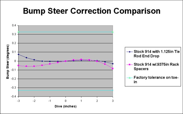 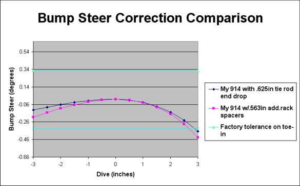 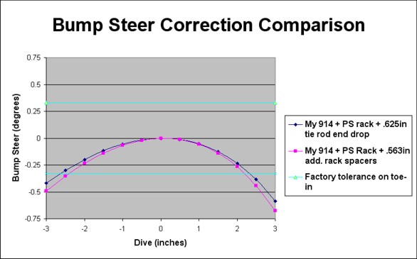 Note the greatly expanded vertical axis in each case. As you can see, it’s possible to achieve an enormous improvement in bump steer correction in all three cases by either method. For the stock 914, it’s possible to reduce the residual to a small fraction of the factory tolerance on the toe setting with rack spacers .9375” thick (not .625”), or with a tie rod end drop of 1.125”. For my lowered car, which already has .625” thick rack spacers in place, the optimum additional rack spacers would be .563” thick for a total of 1.188”, and the optimum tie rod end drop would be .625”. Mounting the VW power steering rack in my car at the same height as the present rack would not change these optimum values, only the amount of the residual bump steer. The correction for my car with either rack isn’t quite a nice as that for the stock 914, but it’s still quite close to being within the factory toe setting tolerance, particularly if I’m willing to adjust the static toe to the upper limit of the tolerance, i.e. 1/3° of toe-in. Interestingly enough, the two methods don’t yield exactly the same results for the same case, the tie rod end drop method always being a tiny, and almost certainly insignificant, bit better. This could be a real, subtle geometric effect, or it could simply be because the program uses a minimum increment size of 1/16” when it varies dimensions. It could be that this level of granularity just happens to find solutions closer to the true optima in the tie rod end drop cases. In any event, dropping the tie rod ends has another important advantage over using rack spacers, in that there’s room to do it. I’m pretty confident, based on my experience 39 years ago, that rack spacers 1.188” or even .9375” thick will not fit without some pretty savage cutting of sheet metal, if you’re using the stock Porsche rack. An unanticipated bonus that comes with converting to the VW PS rack is that it’s enough smaller in diameter than the stock rack, that it CAN be mounted high enough in the car without cutting anything (except, of course, the new hole for the steering input shaft that’s required because the shaft is no longer in the center). So, making the mounting bracket such that it positions the VW rack properly will eliminate the need for the dropped tie rod end kit. Another interesting thing is that the optimum values and residual bump steer performance are as different as they are for the stock 914 and for my car. This is due to geometry changes as you lower the ride height. I verified that by letting the program lower the ride height on the stock 914 to the same height as my car, recalculating the locations of points A, B, and C to restore the correct camber and caster, and then re-optimizing. The values found then are the same as those for my car. I didn’t reproduce any of the graphics of the suspension that the program produces, but these revealed that, at the optimum settings for bump steer, the tie rods and the control arms are always nearly, but not quite, parallel. Presumably, if the tie rods were the same length as the control arms and parallel to them, there would be no bump steer at all. The tie rods aren’t the same length as the control arms, and the difference varies with the ride height because the length of the tie rod must change as the car is lowered in order to keep the same static toe angle. For those of you who might want to know how quickly the bump steer varies as a function of rack position or tie rod end drop, I calculated the following two series showing what happens at various rack spacer thicknesses and tie rod end drop amounts on my 914. Although I didn’t repeat enough of the calculations for the other cases to show the same data for them, I did verify that the sensitivity is very similar. 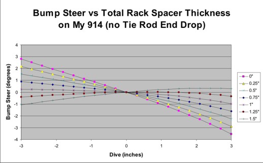 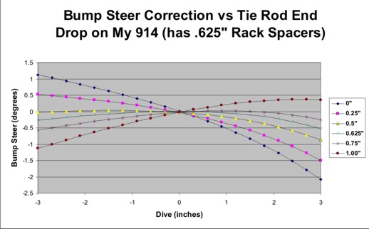 I'll post my efforts at power steering installation as soon as I have it all working. |
   |

 
|
Posts in this topic
 Larry Hubby More about bump steer Nov 29 2010, 10:26 PM
 JRust Holy Hell :WTF: . What a write up :blink: . You d... Nov 29 2010, 11:18 PM championgt1 :agree: Put it in the classics! Nov 29 2010, 11:21 PM Tom_T :agree:
... in the classics Andy, what a treatis... Nov 30 2010, 12:35 AM SirAndy I calculated the following two series showing what... Nov 30 2010, 12:36 AM
JRust Holy Hell :WTF: . What a write up :blink: . You d... Nov 29 2010, 11:18 PM championgt1 :agree: Put it in the classics! Nov 29 2010, 11:21 PM Tom_T :agree:
... in the classics Andy, what a treatis... Nov 30 2010, 12:35 AM SirAndy I calculated the following two series showing what... Nov 30 2010, 12:36 AM
 Larry Hubby
I calculated the following two series showing wha... Nov 30 2010, 01:11 AM SirAndy If you're asking for your particular car
Well,... Nov 30 2010, 01:22 AM 76-914 So is this going to the Classics Thread? I'll ... Nov 30 2010, 08:18 AM jaxdream Great write up , I probably missed it , but the qu... Nov 30 2010, 08:28 AM Racer Chris The downside to large tie rod spacers is torsional... Nov 30 2010, 09:08 AM Brett W Actually it could probably be done pretty easily. ... Nov 30 2010, 09:40 AM Racer Chris
You could machine a spacer that has a female thr... Nov 30 2010, 12:14 PM Brett W
You could machine a spacer that has a female th... Nov 30 2010, 02:50 PM Racer Chris
Yes the only way to make it work at the knuckle e... Nov 30 2010, 04:19 PM brant Larry,
what is the stock ride height?
when you i... Nov 30 2010, 11:32 AM andys It would be interesting to see if measured data us... Nov 30 2010, 11:38 AM banger The Audi A8 tie rod ends have an adjustable drop. ... Nov 30 2010, 12:10 PM windforfun Are you a ME by any chance? Nov 30 2010, 03:09 PM 914 shifter tie rod end spacers ok who sells those? :santa: Nov 30 2010, 04:38 PM elmonte This is the bump steer kit i am running. I think t... Nov 30 2010, 07:01 PM Brett W That design is still pretty scary. You still have... Nov 30 2010, 10:59 PM Larry Hubby Brant,
The factory shop manual tells you to deter... Dec 1 2010, 01:03 AM Larry Hubby Andy,
I'd calculate a series of the optimum t... Dec 1 2010, 01:08 AM KaptKaos Great write up!
I think the ride height was ... Dec 1 2010, 01:30 AM 76-914 :popcorn: with interest Dec 1 2010, 10:43 AM brant awesome
thank you! Dec 1 2010, 01:56 PM jmitro Great thread; found this while searching for steer... Jul 10 2017, 07:57 PM SirAndy Please add to the classics threads
Done and done .... Jul 11 2017, 10:36 AM jim_hoyland Terrific information: from stock, how much may the... Jul 11 2017, 05:54 PM jmitro
Terrific information: from stock, how much may th... Jul 12 2017, 08:02 AM 914_teener Great thread allthough without discussion of the h... Jul 12 2017, 08:39 AM
Larry Hubby
I calculated the following two series showing wha... Nov 30 2010, 01:11 AM SirAndy If you're asking for your particular car
Well,... Nov 30 2010, 01:22 AM 76-914 So is this going to the Classics Thread? I'll ... Nov 30 2010, 08:18 AM jaxdream Great write up , I probably missed it , but the qu... Nov 30 2010, 08:28 AM Racer Chris The downside to large tie rod spacers is torsional... Nov 30 2010, 09:08 AM Brett W Actually it could probably be done pretty easily. ... Nov 30 2010, 09:40 AM Racer Chris
You could machine a spacer that has a female thr... Nov 30 2010, 12:14 PM Brett W
You could machine a spacer that has a female th... Nov 30 2010, 02:50 PM Racer Chris
Yes the only way to make it work at the knuckle e... Nov 30 2010, 04:19 PM brant Larry,
what is the stock ride height?
when you i... Nov 30 2010, 11:32 AM andys It would be interesting to see if measured data us... Nov 30 2010, 11:38 AM banger The Audi A8 tie rod ends have an adjustable drop. ... Nov 30 2010, 12:10 PM windforfun Are you a ME by any chance? Nov 30 2010, 03:09 PM 914 shifter tie rod end spacers ok who sells those? :santa: Nov 30 2010, 04:38 PM elmonte This is the bump steer kit i am running. I think t... Nov 30 2010, 07:01 PM Brett W That design is still pretty scary. You still have... Nov 30 2010, 10:59 PM Larry Hubby Brant,
The factory shop manual tells you to deter... Dec 1 2010, 01:03 AM Larry Hubby Andy,
I'd calculate a series of the optimum t... Dec 1 2010, 01:08 AM KaptKaos Great write up!
I think the ride height was ... Dec 1 2010, 01:30 AM 76-914 :popcorn: with interest Dec 1 2010, 10:43 AM brant awesome
thank you! Dec 1 2010, 01:56 PM jmitro Great thread; found this while searching for steer... Jul 10 2017, 07:57 PM SirAndy Please add to the classics threads
Done and done .... Jul 11 2017, 10:36 AM jim_hoyland Terrific information: from stock, how much may the... Jul 11 2017, 05:54 PM jmitro
Terrific information: from stock, how much may th... Jul 12 2017, 08:02 AM 914_teener Great thread allthough without discussion of the h... Jul 12 2017, 08:39 AM  |
1 User(s) are reading this topic (1 Guests and 0 Anonymous Users)
0 Members:

|
Lo-Fi Version | Time is now: 5th May 2024 - 11:03 AM |
Invision Power Board
v9.1.4 © 2024 IPS, Inc.