|
|
|
Porsche, and the Porsche crest are registered trademarks of Dr. Ing. h.c. F. Porsche AG.
This site is not affiliated with Porsche in any way. Its only purpose is to provide an online forum for car enthusiasts. All other trademarks are property of their respective owners. |
|
|


| JeffBowlsby |
 Dec 10 2010, 10:21 AM Dec 10 2010, 10:21 AM
Post
#1
|
|
914 Wiring Harnesses & Beekeeper  Group: Members Posts: 9,256 Joined: 7-January 03 From: San Ramon CA Member No.: 104 Region Association: None |
Which of these two diagrams is correct...the top or bottom one?
The difference is the hoses at the dizzy vacuum can...they cannot both be right. [NOTE: I deleted the incorrect diagram originally posted...the diagram remaining is the correct configuration] Attached image(s) 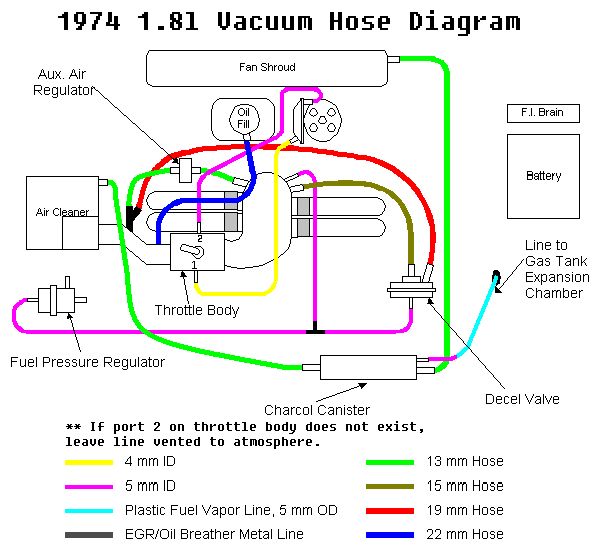
|
   |

 
|
Posts in this topic
 Jeff Bowlsby 1974 1.8L FI Vacuum hoses? Dec 10 2010, 10:21 AM
 Als914 My '74, L-jet is set up to the top diagram sin... Dec 10 2010, 10:33 AM r_towle I have tried both on a 76 2.0 liter.
For emmisions... Dec 10 2010, 10:47 AM Root_Werks Mine is the bottom since I have two ports on the T... Dec 10 2010, 10:48 AM
Als914 My '74, L-jet is set up to the top diagram sin... Dec 10 2010, 10:33 AM r_towle I have tried both on a 76 2.0 liter.
For emmisions... Dec 10 2010, 10:47 AM Root_Werks Mine is the bottom since I have two ports on the T... Dec 10 2010, 10:48 AM
 r_towle
Mine is the bottom since I have two ports on the ... Dec 10 2010, 10:52 AM Root_Werks
Mine is the bottom since I have two ports on the... Dec 10 2010, 10:55 AM Root_Werks Rich, that's pretty interesting. I have my de... Dec 10 2010, 10:52 AM r_towle
Rich, that's pretty interesting. I have my d... Dec 10 2010, 10:53 AM Jeff Bowlsby Uhh, Excuuuuuze me...
This is a thread about the... Dec 10 2010, 11:13 AM Als914
Uhh, Excuuuuuze me...
This is a thread about th... Dec 10 2010, 11:21 AM Root_Werks Sorry Jeff, you're right.
My thoughts are tha... Dec 10 2010, 11:30 AM dr914@autoatlanta.com Hi Jeff I replied right away but forgot to hit the... Dec 10 2010, 11:31 AM pete000
After Jan 1 1974 the vacuum advance was discont... Dec 18 2010, 12:59 AM pete000
After Jan 1 1974 the vacuum advance was discontin... Dec 21 2010, 06:55 PM zonedoubt Probably referring to the 2.0L engine. No 1.8L in ... Dec 22 2010, 12:45 AM zonedoubt I think this discussion would benefit from identif... Dec 10 2010, 04:05 PM jsayre914 i am running the bottom diagram on the motor i jus... Dec 10 2010, 05:49 PM Sailor My 74 is set up to the bottom diagram. Dec 10 2010, 07:56 PM Jeff Bowlsby Thanks everyone, looks like the bottom diagram is ... Dec 11 2010, 09:12 AM Als914
Thanks everyone, looks like the bottom diagram is... Dec 11 2010, 11:16 AM Als914
Thanks everyone, looks like the bottom diagram i... Dec 11 2010, 11:38 AM Jeff Bowlsby Yes... Dec 11 2010, 03:28 PM pete000 This is what it should look like if the second vac... Dec 15 2010, 07:56 PM Jeff Bowlsby
This is what it should look like if the second va... Dec 16 2010, 01:13 AM zonedoubt
A short three inch piece of tubing going no where... Dec 16 2010, 01:03 PM Cap'n Krusty There are some disturbing errors throughout this t... Dec 16 2010, 02:42 PM pete000
There are some disturbing errors throughout this ... Dec 18 2010, 12:50 AM zonedoubt
...there's a specific procedure for doing so.... Dec 21 2010, 06:23 PM zonedoubt I have seen several Ljet equipped engines with the... Dec 17 2010, 12:57 AM pete000 This seems to be a controversial topic ! :cho... Dec 18 2010, 12:44 AM zonedoubt This is probably due to some confusion with 2.0L v... Dec 19 2010, 10:09 PM Jeff Bowlsby We need a 'dog-chasing-his-tail' smiley be... Dec 18 2010, 01:07 PM pete000 Here is a photo of my TB on my 74 1.8 L-Jet I am c... Dec 18 2010, 05:45 PM zonedoubt Single port on throttle body to distributor vacuum... Dec 19 2010, 09:57 PM zonedoubt This is a two-vacuum-port throttle body (p/n 022 1... Dec 19 2010, 10:00 PM Cap'n Krusty I've worked on the 1.8s since BEFORE they were... Dec 21 2010, 06:44 PM Dave_Darling Check the position of the vacuum fittings on the t... Dec 22 2010, 02:11 AM pete000
Check the position of the vacuum fittings on the ... Dec 22 2010, 12:42 PM zonedoubt
Ok let me get this right, if the car came with on... Dec 22 2010, 02:25 PM Dave_Darling I think this could only be proven by looking at th... Dec 23 2010, 08:29 PM jim_hoyland My '75 1.8 L-Jet has the 2 port throttle body;... Dec 22 2010, 10:51 AM Root_Werks :blink:
My head hurts. Dec 22 2010, 03:16 PM markb
:blink:
My head hurts.
:agree: Dec 22 2010, 03:33 PM pete000 Revisiting this old thread.
I have pulled off my... Oct 6 2015, 01:17 AM rhodyguy the portion of the diagram the notes the charcoal ... Oct 6 2015, 06:57 AM
r_towle
Mine is the bottom since I have two ports on the ... Dec 10 2010, 10:52 AM Root_Werks
Mine is the bottom since I have two ports on the... Dec 10 2010, 10:55 AM Root_Werks Rich, that's pretty interesting. I have my de... Dec 10 2010, 10:52 AM r_towle
Rich, that's pretty interesting. I have my d... Dec 10 2010, 10:53 AM Jeff Bowlsby Uhh, Excuuuuuze me...
This is a thread about the... Dec 10 2010, 11:13 AM Als914
Uhh, Excuuuuuze me...
This is a thread about th... Dec 10 2010, 11:21 AM Root_Werks Sorry Jeff, you're right.
My thoughts are tha... Dec 10 2010, 11:30 AM dr914@autoatlanta.com Hi Jeff I replied right away but forgot to hit the... Dec 10 2010, 11:31 AM pete000
After Jan 1 1974 the vacuum advance was discont... Dec 18 2010, 12:59 AM pete000
After Jan 1 1974 the vacuum advance was discontin... Dec 21 2010, 06:55 PM zonedoubt Probably referring to the 2.0L engine. No 1.8L in ... Dec 22 2010, 12:45 AM zonedoubt I think this discussion would benefit from identif... Dec 10 2010, 04:05 PM jsayre914 i am running the bottom diagram on the motor i jus... Dec 10 2010, 05:49 PM Sailor My 74 is set up to the bottom diagram. Dec 10 2010, 07:56 PM Jeff Bowlsby Thanks everyone, looks like the bottom diagram is ... Dec 11 2010, 09:12 AM Als914
Thanks everyone, looks like the bottom diagram is... Dec 11 2010, 11:16 AM Als914
Thanks everyone, looks like the bottom diagram i... Dec 11 2010, 11:38 AM Jeff Bowlsby Yes... Dec 11 2010, 03:28 PM pete000 This is what it should look like if the second vac... Dec 15 2010, 07:56 PM Jeff Bowlsby
This is what it should look like if the second va... Dec 16 2010, 01:13 AM zonedoubt
A short three inch piece of tubing going no where... Dec 16 2010, 01:03 PM Cap'n Krusty There are some disturbing errors throughout this t... Dec 16 2010, 02:42 PM pete000
There are some disturbing errors throughout this ... Dec 18 2010, 12:50 AM zonedoubt
...there's a specific procedure for doing so.... Dec 21 2010, 06:23 PM zonedoubt I have seen several Ljet equipped engines with the... Dec 17 2010, 12:57 AM pete000 This seems to be a controversial topic ! :cho... Dec 18 2010, 12:44 AM zonedoubt This is probably due to some confusion with 2.0L v... Dec 19 2010, 10:09 PM Jeff Bowlsby We need a 'dog-chasing-his-tail' smiley be... Dec 18 2010, 01:07 PM pete000 Here is a photo of my TB on my 74 1.8 L-Jet I am c... Dec 18 2010, 05:45 PM zonedoubt Single port on throttle body to distributor vacuum... Dec 19 2010, 09:57 PM zonedoubt This is a two-vacuum-port throttle body (p/n 022 1... Dec 19 2010, 10:00 PM Cap'n Krusty I've worked on the 1.8s since BEFORE they were... Dec 21 2010, 06:44 PM Dave_Darling Check the position of the vacuum fittings on the t... Dec 22 2010, 02:11 AM pete000
Check the position of the vacuum fittings on the ... Dec 22 2010, 12:42 PM zonedoubt
Ok let me get this right, if the car came with on... Dec 22 2010, 02:25 PM Dave_Darling I think this could only be proven by looking at th... Dec 23 2010, 08:29 PM jim_hoyland My '75 1.8 L-Jet has the 2 port throttle body;... Dec 22 2010, 10:51 AM Root_Werks :blink:
My head hurts. Dec 22 2010, 03:16 PM markb
:blink:
My head hurts.
:agree: Dec 22 2010, 03:33 PM pete000 Revisiting this old thread.
I have pulled off my... Oct 6 2015, 01:17 AM rhodyguy the portion of the diagram the notes the charcoal ... Oct 6 2015, 06:57 AM  |
1 User(s) are reading this topic (1 Guests and 0 Anonymous Users)
0 Members:

|
Lo-Fi Version | Time is now: 28th May 2026 - 10:20 AM |
Invision Power Board
v9.1.4 © 2026 IPS, Inc.