|
|
|
Porsche, and the Porsche crest are registered trademarks of Dr. Ing. h.c. F. Porsche AG.
This site is not affiliated with Porsche in any way. Its only purpose is to provide an online forum for car enthusiasts. All other trademarks are property of their respective owners. |
|
|

  |

| watsonrx13 |
 Jan 17 2011, 06:55 AM Jan 17 2011, 06:55 AM
Post
#1
|
|
Advanced Member  Group: Members Posts: 2,734 Joined: 18-February 03 From: Plant City, FL Member No.: 312 Region Association: South East States |
Since I've rebuilt my '74 2.0l FI engine I've had problems with the car not idling. After it warms up it dies. I've set the timing to 27 and the dwell is at 46. I tried adjusting the ECU knob and the air idle screw but neither appear to have any effect on the idle. When I adjust the knob I can feel it click. I counted 21 total clicks. The engine runs great above idle. The injectors have been rebuilt, new AA vacuum hoses replaced, all gaskets are new.
Can the ECU be taken apart and cleaned? Does anyone have a pic of the ECU opened up showing the knob area? Any recommendations on how to fix the idle problem I'm having? -- Rob |
   |

 
|
| gasman |
Jan 17 2011, 10:11 AM
Post
#2
|
|
Member Group: Members Posts: 107 Joined: 21-January 08 From: Mooresville, nc Member No.: 8,602 Region Association: South East States |
First check that the AAR is fully closed when warm (pull hose off air cleaner and make sure it's not sucking) if it is, you have to free up AAR and make sure it has 12 volts to it. Also. the ECU knob will only work if the TPS is adjusted correctly. Check AAR and TPS
|
|
|
|
| r_towle |
Jan 17 2011, 10:16 AM
Post
#3
|
|
Custom Member Group: Members Posts: 24,577 Joined: 9-January 03 From: Taxachusetts Member No.: 124 Region Association: North East States |
I would agree that something else it wrong.
The knob really does not do alot...it just adds fuel during idle and with to much it will stall. Consider running through the troubleshooting section of Brad's D-jet site...very sytematically. Rich |
|
|
|
| Jeffs9146 |
Jan 17 2011, 10:20 AM
Post
#4
|
|
Ski Bum Group: Members Posts: 4,062 Joined: 10-January 03 From: Discovery Bay, Ca Member No.: 128 |
QUOTE After it warms up it dies. Check your CHTS (Cylinder Head Temp Sensor) This caused the same symptom in my 74fi! Turned out the threads were stripped and it would work sometimes and not others! |
|
|
|
| jsayre914 |
Jan 17 2011, 11:33 AM
Post
#5
|
|
Speed Up !!! Group: Members Posts: 3,188 Joined: 10-February 08 From: Timonium MD 21093 Member No.: 8,696 Region Association: MidAtlantic Region |
Vacume leak?? Check all the hoses are tight and make sure none are split. also make sure the valve covers are seated properly, i once had a valve cover gasket get sucked in on one side creating a terrible idle.
(IMG:style_emoticons/default/confused24.gif) |
|
|
|
| watsonrx13 |
Jan 17 2011, 11:57 AM
Post
#6
|
|
Advanced Member Group: Members Posts: 2,734 Joined: 18-February 03 From: Plant City, FL Member No.: 312 Region Association: South East States |
So if I read Brad website correctly I need a 0 280 130 003 head temp sensor. Is the number stamped on the sensor? What is the Porsche part number, I'd like to order this thru my local Porsche dealer.
BTW I did add the spacer that Brad built should I remove this first then test again? -- Rob |
|
|
|
| Krieger |
Jan 17 2011, 12:27 PM
Post
#7
|
|
Advanced Member Group: Members Posts: 4,714 Joined: 24-May 04 From: Santa Rosa CA Member No.: 2,104 Region Association: None |
QUOTE(watsonrx13 @ Jan 17 2011, 09:57 AM)  So if I read Brad website correctly I need a 0 280 130 003 head temp sensor. Is the number stamped on the sensor? What is the Porsche part number, I'd like to order this thru my local Porsche dealer. BTW I did add the spacer that Brad built should I remove this first then test again? -- Rob The spacer if installed correctly will not be a problem. Test your sensor first, before you replace it. I think the spec is 2000 ohms when cold. O ohms hot. Hook your multimeter up and jiggle the wire and see what happens. |
|
|
|
| messix |
Jan 17 2011, 01:15 PM
Post
#8
|
|
AKA "CLUTCH KILLER"! Group: Members Posts: 6,995 Joined: 14-April 05 From: between shit kickers and pinky lifters/ puget sound wa.north of Seattle south of Canada Member No.: 3,931 Region Association: Pacific Northwest |
oil fill cap not tight?
|
|
|
|
| r_towle |
Jan 17 2011, 02:24 PM
Post
#9
|
|
Custom Member Group: Members Posts: 24,577 Joined: 9-January 03 From: Taxachusetts Member No.: 124 Region Association: North East States |
Here is how I go about this...and it works.
Unplug every vacuum line from the plenum and cap them at the plenum. Leave only the large MPS line attached. Start the car and see if you still have an issue. If so, Head for the ignition system and check it all again... Dirty distributor and 0.05 cents of grease will free up the vacuum advance plates to get them moving properly. If none of that works, its time for wiring harness, CHT diagnosis. If you find that unplugging the vacuum lines does the trick, you plug back in one system at a time...so AAR, then test...Decel valve, then test...do it one at a time to find the issue. AAR can leak and not close...bad idle Decel valve can be junk...bad idle See the trend... Rich |
|
|
|
| SLITS |
Jan 17 2011, 08:26 PM
Post
#10
|
|
"This Utah shit is HARSH!" Group: Benefactors Posts: 13,602 Joined: 22-February 04 From: SoCal Mountains ... Member No.: 1,696 Region Association: None |
Make sure the knob is in the middle of the range ... Then one click at a time and let the engine stabilize, readjust idle bleed screw.
I usually find 12 - 13 clicks to be the best from max lean. Oh, counter clockwise = leaner .... Clockwise = richer *** only at idle. |
|
|
|
| detoxcowboy |
Jan 18 2011, 12:23 AM
Post
#11
|
|
Senior Member Group: Members Posts: 1,294 Joined: 30-January 08 Member No.: 8,642 Region Association: Africa |
QUOTE(watsonrx13 @ Jan 17 2011, 04:55 AM) Since I've rebuilt my '74 2.0l FI engine I've had problems with the car not idling. After it warms up it dies. I've set the timing to 27 and the dwell is at 46. I tried adjusting the ECU knob and the air idle screw but neither appear to have any effect on the idle. When I adjust the knob I can feel it click. I counted 21 total clicks. The engine runs great above idle. The injectors have been rebuilt, new AA vacuum hoses replaced, all gaskets are new. Can the ECU be taken apart and cleaned? Does anyone have a pic of the ECU opened up showing the knob area? Any recommendations on how to fix the idle problem I'm having? -- Rob Just a heads up.. One Click at a time and wait for the response, do it when the car has been drivin for 20-30 minutes. ect.. -The air bleed screw will have no effect if your mixture is too lean, -Your car will want to die the more it is warmed up if your mixture is too rich.. were are talking excessive adjustment but it is easy to get lost, and also being incremental and making sure your adjusting only when your car is fully warmed up, 20-30 minutes driving, not idling in your drive way.. plus if you have another minor issue going on it is possible to adjust masking that issue but causing really poor adjustment.. side not on this extremely valuable link, he is getting a cold idle of 1700 rpm before it is warmed up, and i am yet to ever have that high of an idle.. I go from about 1200rpm start up in so. cal. temps, but was getting 1500 in below freezing in WA... my aar is good in fact I have a couple very sweet ones and they both respond exactly the same.. Anyway this link will learn you the d-jet and once you do that, Your Golden! The writer is Pbanders a 914 world meber also.. There is more about the ecu in this site than you ever want to know.. Linky... http://members.rennlist.com/pbanders/ |
|
|
|
| detoxcowboy |
Jan 18 2011, 11:07 AM
Post
#12
|
|
Senior Member Group: Members Posts: 1,294 Joined: 30-January 08 Member No.: 8,642 Region Association: Africa |
I also have a 74 2.0, (IMG:style_emoticons/default/agree.gif) there is another problem, start with your throttle position sensor.. make certain it is adjusted properly..my experience says that is your problem, then set your idle. I would'nt take the ecu apart..
The ECU potentiometer only works at idle, or more exactly, when the idle contacts in the TPS are closed. When the TPS idle contacts open upon opening the throttle, the ECU enrichment circuits take over. 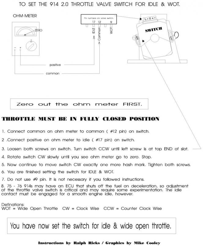 |
|
|
|
| watsonrx13 |
Jan 31 2011, 05:23 PM
Post
#13
|
|
Advanced Member Group: Members Posts: 2,734 Joined: 18-February 03 From: Plant City, FL Member No.: 312 Region Association: South East States |
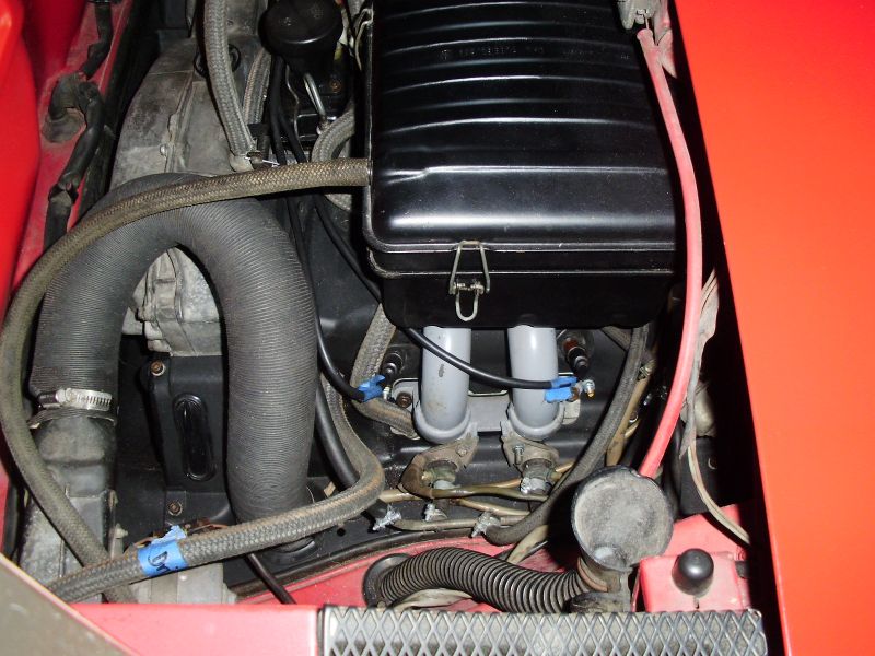
I was finally able to work on the car this weekend. I'm still having problems with the engine not idling, hot or cold. I took the car out for a quick drive and didn't have any issues except when I stopped.
I went by after work and checked the following. After reinstalling the AAR I wasn't able to start the car at all now. Here are the components that I checked: 1. MSP - I pumped it up to 20hg. I checked it again in 5 min and it was at 17hg. 2. I removed the AAR and hooked it up to a 12v power supply. At the end of 10 min it had heated up and the valve had closed. 3. I checked the CHT when it was cold but only got a reading of 1, regardless of the ohm settitng. After the car was warmed up I disconnected the CHT and hooked a wire directly to ground, which seemed to help. 4. I reset the TPS as suggested above. 5. All of the vacuum hoses are new and tight. 5. All of the seals are new. What components make up the idle circuit? It appears that something is telling the ECU that the motor is not running and therefore no fuel is being injected when in the idle mode. Here are some pics of the vacuum lines, does anyone see anything wrong? BTW I used AA's vacuum hose diagram. 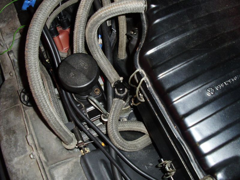 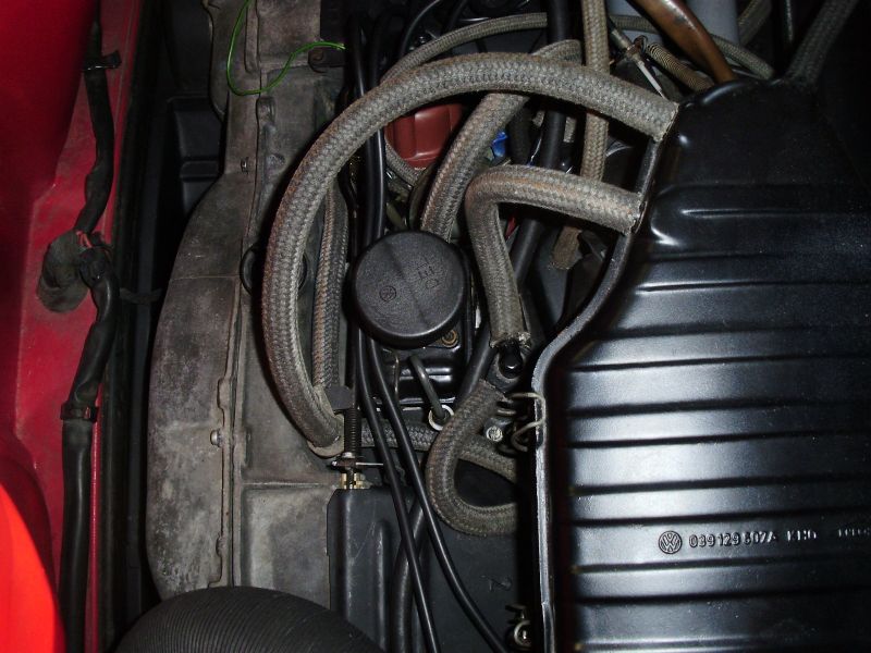 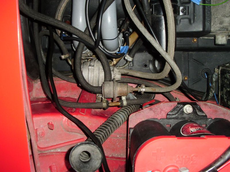 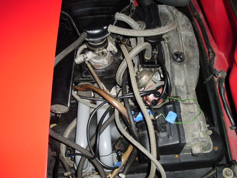 -- Rob |
|
|
|
| watsonrx13 |
Jan 31 2011, 05:24 PM
Post
#14
|
|
Advanced Member Group: Members Posts: 2,734 Joined: 18-February 03 From: Plant City, FL Member No.: 312 Region Association: South East States |
more pics..
 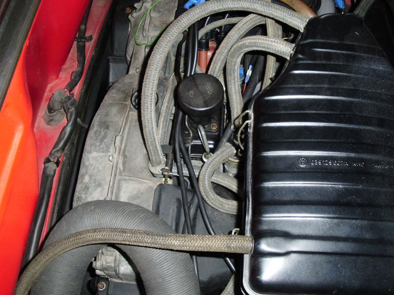 Here's how I tested the AAR... 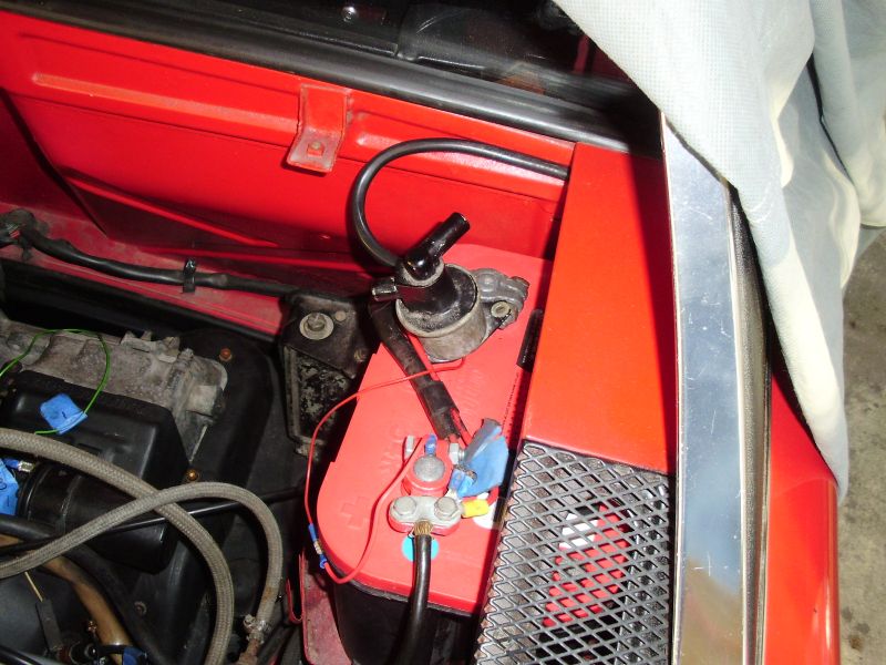 -- Rob |
|
|
|
| Jeffs9146 |
Jan 31 2011, 05:51 PM
Post
#15
|
|
Ski Bum Group: Members Posts: 4,062 Joined: 10-January 03 From: Discovery Bay, Ca Member No.: 128 |
I still vote for CHTS!!!!
|
|
|
|
| sfrenck |
Jan 31 2011, 06:12 PM
Post
#16
|
|
Member Group: Members Posts: 492 Joined: 28-February 10 From: Wilmington, DE Member No.: 11,411 Region Association: MidAtlantic Region |
QUOTE(watsonrx13 @ Jan 31 2011, 06:23 PM) I was finally able to work on the car this weekend. I'm still having problems with the engine not idling, hot or cold. I took the car out for a quick drive and didn't have any issues except when I stopped. I went by after work and checked the following. After reinstalling the AAR I wasn't able to start the car at all now. Here are the components that I checked: 1. MSP - I pumped it up to 20hg. I checked it again in 5 min and it was at 17hg. 2. I removed the AAR and hooked it up to a 12v power supply. At the end of 10 min it had heated up and the valve had closed. 3. I checked the CHT when it was cold but only got a reading of 1, regardless of the ohm settitng. After the car was warmed up I disconnected the CHT and hooked a wire directly to ground, which seemed to help. 4. I reset the TPS as suggested above. 5. All of the vacuum hoses are new and tight. 5. All of the seals are new. What components make up the idle circuit? It appears that something is telling the ECU that the motor is not running and therefore no fuel is being injected when in the idle mode. Here are some pics of the vacuum lines, does anyone see anything wrong? BTW I used AA's vacuum hose diagram. -- Rob CHT reading of 1 doesn't sound right. It's a very inexpensive part for the 74 2.0L: <$20 shipped from Pelican (311-906-041-A-M14). I'd then find a '74 ECU to borrow to rule that out. |
|
|
|
| detoxcowboy |
Jan 31 2011, 06:19 PM
Post
#17
|
|
Senior Member Group: Members Posts: 1,294 Joined: 30-January 08 Member No.: 8,642 Region Association: Africa |
CHT Value and issue,
Function: Senses engine temperature and sends signal to the ECU to provide mixture compensation. Proper part for your application and proper functioning is extremely important! Normal Value(s): 0 280 130 003 and 0 280 130 012: about 2.5 K ohms at 68 deg. F, less than 100 ohms with hot engine. 0 280 130 017: about 1.3 K ohms at 68 deg. F, less than 100 ohms with hot engine. See Notes section below for more data on the resistance vs. temperature values of these sensors. Failure Modes Open: The ECU interprets an open sensor as a signal to greatly richen (e.g. I've measured an over 3X effect) the mixture. This usually makes the car impossible to start and causes it to stall if the sensor fails open while running. Check by disconnecting the sensor from the wiring harness and measuring the resistance to ground, refer to the values above. Shorted: The ECU interprets a shorted sensor as a signal to lean out the mixture (about 30% leaner). The car may run and start in this condition, but will have poor idle and drivability. Check by disconnecting the sensor from the wiring harness and checking the resistance to ground. Note that shorts are often intermittent, caused by nicks in the sensor wire and by exposed contacts to the wiring harness touching ground. Check by inspection. Stuck Value: I've heard of at least one case of the sensor being stuck at a value (e.g. 50 ohms) and not varying with temperature. Depending on the value it gets stuck at, it can result in either poor cold or hot performance, or both. Check by measuring with an ohmmeter as described above. Mismatched: The 1973 2.0L's came with the 0 280 130 017 head temperature sensor, 039 971 762 A ballast resistor, 0 280 100 037 manifold pressure sensor, and the 022 906 021 E version of the ECU. This set of components must be used together. Any substitution will result in idle and part-load performance problems, and possible poor fuel economy. Additionally, use of any of these 1973 2.0L components with a 1974 2.0L setup will also cause problems. See the table above for the suggested setup for both 1973 or 1974 2.0L engines. If you have a 1973 2.0L and you want to keep the original setup, make absolutely certain that you have the correct combination of components. The 0 280 130 017 head temperature sensor's cold (70 deg F.) resistance is about 1200 ohms, compared to 2300 ohms for the 0 280 130 003 and 0 280 130 012 sensors. Use of the ...017 sensor with the 039 906 021 ECU (1974 model) will result in a lean mixture during warm up, causing low idle and/or backfiring on over-run. Use of the ...012 or ...003 sensor with the 022 906 021 E ECU (1973 model), with or without the ballast resistor, will result in a rich warm-up mixture. Take the extra time and determine exactly which head temperature sensor is installed in your car and make sure it matches the setup. Notes: This resistance of this sensor is one of the primary factors in adjusting the mixture and it has a strong effect. An additional issue is the availability of the 0 280 130 012 sensor. I have found this sensor difficult to locate, and most shops substitute the 0 280 130 003 sensor for it. As far as I can tell, it is either exactly the same or nearly identical. Bosch even lists the ...003 sensor as being cross-referenced to the Porsche/VW part number 311 906 041 A. See the entry above for the intake air temperature sensor for theory on how these sensors work. Fixes for Crappy Warm-Up: For whatever reason, VW/Porsche made the CHT sensor such that the warm-up mixture is usually too lean, resulting in poor idle and drivability. Two ways to fix this. First, you can add up to 150 ohms of ballast resistance to the sensor to bias the curve up towards a richer condition. Don't go over this amount of ballast because it will begin to affect the warmed-up mixture. Second, you can construct a spacer as described on Richard Atwell's page, that delays heat transfer from the head to the sensor, making the mixture richer during warm-up. I made mine using materials from my local ACE Hardware: a M10x1.0 tap and wrench, 11/32" drill bit, M10x1.0 bolt, and a M8x1.25 coupling nut w/13 MM hex. Drill out the coupling nut and tap it to M10x1.0. Cut it down to 16 MM length. Cut a 16 MM stud from the bolt, thread it into the coupling nut so that when you attach the sensor on the other end, it just jams the stud in place. Align the flats and install. BTW, you can also do both fixes in combination (like on my car!). Installation Notes: Installing this sensor can be tricky. The best solution I've found is to buy a deep 13 mm socket and a 3" extension (I bought mine at Checker, about $5 for both). Use a Dremel tool with a cut-off wheel to cut off one of the corners of the four-sided end of the extension (the part that goes into the socket) to create a gap that the sensor wire can be threaded through. ALWAYS USE SAFETY GLASSES when doing this kind of work with a Dremel tool. Filing works, too, but it will take a very long time. Make sure to use the copper washer that comes with the sensor - the washer assures good thermal conductivity to the head and prevents loosening. Keeping the washer from falling off during installation can be difficult. First, to keep the sensor from being pushed back into the socket during installation (which will pop the washer off, and it'll fall into the head air fins), position the sensor so that it's sticking out a bit, then tape the wire with a single loop of masking tape to the extension. The wire will resist the sensor being pushed back into the socket. To keep the washer on the sensor, I use a couple of tiny drops of superglue to hold it in place. The glue bond will be broken when the sensor is tightened. DO NOT overtighten this sensor, just get it snug. It's easy to strip out the head threads and then you'll have to pull the engine to fix the problem. More Data!!: Below is some characterization data I took on each sensor at three different temperatures (one data point missing). Note that these are representative readings - there is significant manufacturing variation in these sensors. All data measured with a freshly-calibrated Wavetek LCR55 meter. Sensor Temp = 39 deg. F (ice bath with thermometer) Temp = 61 deg. F (room temperature) Temp = 210 deg F (boiling water at 1000 feet altitude) 0 280 130 003 6.10 K ohms 2.94 K ohms 199.3 ohms 0 280 130 012 NA 2.85 K ohms 191.2 ohms 0 280 130 017 3.63 K ohms 1.74 K ohms 124.7 ohms Ballast Resistor Function: Biases the resistance of the head temperature sensor across the entire temperature range to cause the ECU to provide a overall richer mixture. Only used on 1973 2.0L's. Normal Value(s): 270 ohms Failure Modes Open: Same effect as an open head temperature sensor (see above). Check with an ohmmeter. Shorted: Eliminates bias from head temperature sensor. Causes leaner mixture across full range of operation, resulting in drivability problems, possible backfiring. Check with an ohmmeter. Mismatched or wrong value: Many owners are aware that using a resistor to bias the head temperature sensor is a way of affecting the overall mixture of the D-Jetronic system. Depending on the value used and the setup, you can end up with a lean or rich mixture. Using a bias resistor other than as specified for the 1973 2.0L is only suggested when there is no alternative to obtaining good drivability. Notes: Used only on the 1973 2.0L engines in the combination of components described above in the cylinder head temperature section. It is used to bias the resistance of the 0 280 130 017 cylinder head temperature sensor. Since the ...017 sensor has a cold resistance value of about 1300 ohms, and a warm value of less than 100 ohms, use of the ballast resistor increases the value the ECU sees at both extremes by 270 ohms. If this resistor is missing from a 1973 setup, the mixture will be too lean across the whole temperature range. Use of this resistor in a 1974 setup will result in a rich mixture when the engine is warm. Make sure that if you have a 1973 setup as described above, that this resistor is present, and if you have a 1974 setup, that it isn't installed. |
|
|
|
| watsonrx13 |
Jan 31 2011, 07:19 PM
Post
#18
|
|
Advanced Member Group: Members Posts: 2,734 Joined: 18-February 03 From: Plant City, FL Member No.: 312 Region Association: South East States |
Thanks guys. I also believe it appears to be a problem with the CHT so I'm going to order one tomorrow.
Now how do you remove and replace? Do I need to take the intake runner off? -- Rob |
|
|
|
| Jeffs9146 |
Jan 31 2011, 07:43 PM
Post
#19
|
|
Ski Bum Group: Members Posts: 4,062 Joined: 10-January 03 From: Discovery Bay, Ca Member No.: 128 |
QUOTE Now how do you remove and replace? Do I need to take the intake runner off? It is not hard but be very carefull not to cross thread it when putting it back in!! Passenger side between the two cylinders there is a loan wire coming out from the tin! You need to make a tool out of a socket extension by putting a notch in one edge of the extension so the wire can feed through and out the top! I will see if I can find mine and take a photo! Sorry, I couldn't find my notched extension!! |
|
|
|
| Spoke |
Feb 1 2011, 05:58 AM
Post
#20
|
|
Jerry Group: Members Posts: 6,983 Joined: 29-October 04 From: Allentown, PA Member No.: 3,031 Region Association: None |
One simple test you can do to make sure your CHT is faulty is get a 300-2K ohm resistor and with jumper wires, connect the resistor from ground to the CHT wire.
This will fool the ECU to think the engine is at the temperature that results when the CHT sender is at that resistance. 2K would be closer to cold engine, 300 would be fully warmed. The resistor can be very small (low wattage) as there is not much current in the CHT sender. 1/8W resistor will work fine for the test. AAR or other vacuum leak will only cause the engine to idle faster. With enough vacuum leak, the engine will hunt as it races to 1800 RPM or so, then dies as the fuel is cut-off like you're deaccelerating, then turn back on when the engine nears idle speed. BTW, it looks like you have a missing hose on the vacuum advance unit. Can't tell if a hose is connected here. Attached image(s) 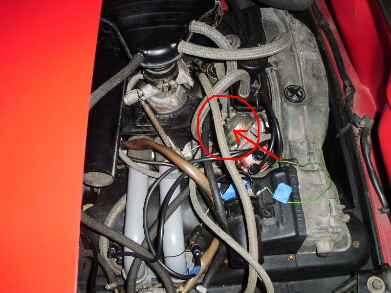
|
|
|
|
|
1 User(s) are reading this topic (1 Guests and 0 Anonymous Users)
0 Members:

|
Lo-Fi Version | Time is now: 21st May 2024 - 07:26 AM |
Invision Power Board
v9.1.4 © 2024 IPS, Inc.