|
|
|
Porsche, and the Porsche crest are registered trademarks of Dr. Ing. h.c. F. Porsche AG.
This site is not affiliated with Porsche in any way. Its only purpose is to provide an online forum for car enthusiasts. All other trademarks are property of their respective owners. |
|
|

  |

| Randal |
 Feb 14 2011, 06:41 PM Feb 14 2011, 06:41 PM
Post
#1
|
|
Advanced Member  Group: Members Posts: 4,446 Joined: 29-May 03 From: Los Altos, CA Member No.: 750 |
I am going to be putting my engine in by myself, so trying to get everything lined up so it will be a smooth process.
My throttle bodies and fuel rails are wider than the stock sheet metal, so will be removing one of them so I won't have to use crazy angles (again) to get the engine back up in there. My engine is about as high as one with Webers. 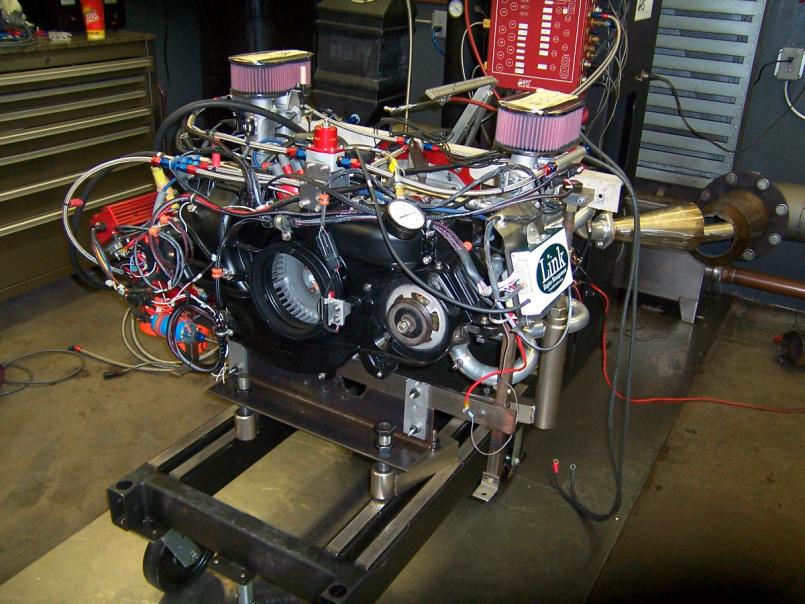 I've built two large wide ramps and extra blocks so that I can have the rear wheel about 14" off the ground. Don't have my car here so can't test it out, but figured all you jack stand / car ramp guys will know if that is high enough for my engine to fit under the bumper. If not, some more 2 x 6's are going to get cut up for blocks. |
   |

 
|
| J P Stein |
Feb 14 2011, 06:56 PM
Post
#2
|
|
Irrelevant old fart Group: Members Posts: 8,797 Joined: 30-December 02 From: Vancouver, WA Member No.: 45 Region Association: None |
For my weber carbed 2.7L I needed 32 inches from the ground to the rear bulkhead. The lifting gear under the motor was about 8 inches tall.
I permanently removed all the sheet metal from the motor and the engine shelf (both sides) without causing any heat problems......the engine room did get dirtier, tho. After pushing the motor /trans in rough place and jacking the thing to full extension, I'd block the cradle in place then add a 10 inch box on the jack and take it the rest of the way up. I got good at doing it solo but extra help is good JIC. Attached thumbnail(s) 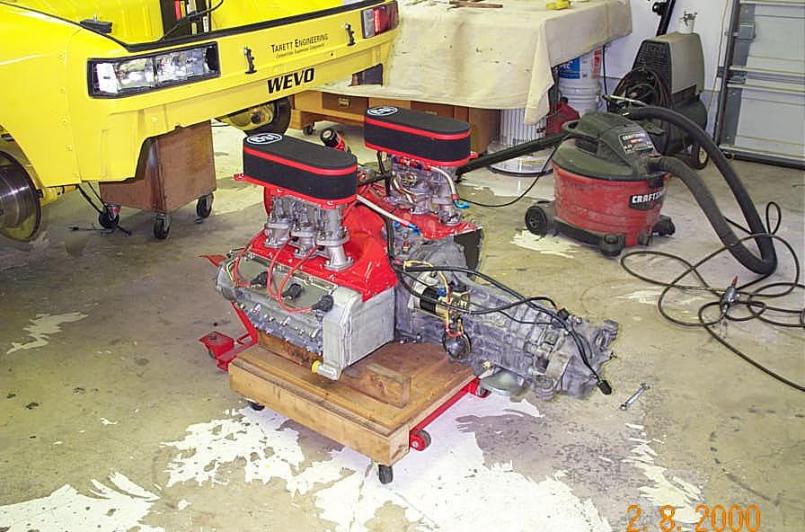
|
|
|
|
| Borderline |
Feb 14 2011, 11:20 PM
Post
#3
|
|
Senior Member Group: Members Posts: 720 Joined: 8-February 05 From: San Juan Bautista, CA Member No.: 3,577 Region Association: Northern California |
I don't like having the car that high in the air, so I remove the carbs and air cleaners and leave the intake manifolds with some tape over them to keep any crud out. then after the engine is in, I re-assemble the carbs. Also, I leave the headers off until after the engine is installed. Personal preference, I guess.
|
|
|
|
| ChrisFoley |
Feb 15 2011, 09:51 AM
Post
#4
|
|
I am Tangerine Racing Group: Members Posts: 7,911 Joined: 29-January 03 From: Bolton, CT Member No.: 209 Region Association: None |
One of our lift plates gets the engine down to about 4" from the floor, on a jack that will raise it 14" or more (IMG:style_emoticons/default/smile.gif)
With the TBs out of the way you have a chance with the car at the level you mentioned Randal. You may have to get creative lowering the car a little bit to meet the engine before any of the bolts will go in. |
|
|
|
| Randal |
Feb 15 2011, 02:14 PM
Post
#5
|
|
Advanced Member Group: Members Posts: 4,446 Joined: 29-May 03 From: Los Altos, CA Member No.: 750 |
QUOTE(Racer Chris @ Feb 15 2011, 07:51 AM)  One of our lift plates gets the engine down to about 4" from the floor, on a jack that will raise it 14" or more (IMG:style_emoticons/default/smile.gif) With the TBs out of the way you have a chance with the car at the level you mentioned Randal. You may have to get creative lowering the car a little bit to meet the engine before any of the bolts will go in. Thanks Chris. As you suggested the TB's will be out of the way. I'd cut the sheet metal, but Paul (built my engine) would be unhappy given all the effort he took to maintain engine cooling. After carefully looking at one of the HF transmission jacks I decided to buy one for this job. It has the ability to alter angle fairly dramatically basically North, South East or West. It is made pretty well and I think it will do what is needed. We'll see how it works when I have the motor, along with the transmission, on it. BTW I made a block to protect the special oil sump and that fits precisely into the top of the jack plate. I'll strap the engine to that plate with tie down straps. So I should be able to get the engine to the right height to allow the bolts to go in. Just waiting until this rain goes away and then the motor is going in. We need that T-Shirt weather that was here last week! |
|
|
|
| ChrisFoley |
Feb 15 2011, 07:52 PM
Post
#6
|
|
I am Tangerine Racing Group: Members Posts: 7,911 Joined: 29-January 03 From: Bolton, CT Member No.: 209 Region Association: None |
QUOTE(Randal @ Feb 15 2011, 03:14 PM) BTW I made a block to protect the special oil sump and that fits precisely into the top of the jack plate. I'll strap the engine to that plate with tie down straps. The balance point of a 4 cyl. engine/transmission ass'y is very close to the rear of the engine. |
|
|
|
| draganc |
Feb 15 2011, 10:16 PM
Post
#7
|
|
Senior Member Group: Members Posts: 725 Joined: 2-November 09 From: central new jersey Member No.: 11,000 Region Association: North East States |
Great looking engine and very interesting setup!!
Do you mind sharing some information about the “crank” sensor (I believe you have mounted it next to the fan) and the fuel rail set-up? Thanks, Dragan PS: Are those Tangerine headers? |
|
|
|
| Randal |
Feb 16 2011, 05:02 AM
Post
#8
|
|
Advanced Member Group: Members Posts: 4,446 Joined: 29-May 03 From: Los Altos, CA Member No.: 750 |
QUOTE(draganc @ Feb 15 2011, 08:16 PM) Great looking engine and very interesting setup!! Do you mind sharing some information about the “crank” sensor (I believe you have mounted it next to the fan) and the fuel rail set-up? Thanks, Dragan PS: Are those Tangerine headers? Tangerine headers, yes. Chris Foley made them and they work well. When first testing the engine couldn't get the bounce out of the Mallory distributor, even with several changes, blueprinting, etc., so the engine builder set up a crank sensor that has very little bounce. The Mallory is the backup. I'll take some closer pictures of the fuel rail set up, along with the fuel regulator and filters. |
|
|
|
| draganc |
Feb 16 2011, 07:34 AM
Post
#9
|
|
Senior Member Group: Members Posts: 725 Joined: 2-November 09 From: central new jersey Member No.: 11,000 Region Association: North East States |
QUOTE(Randal @ Feb 16 2011, 03:02 AM) QUOTE(draganc @ Feb 15 2011, 08:16 PM) Great looking engine and very interesting setup!! Do you mind sharing some information about the “crank” sensor (I believe you have mounted it next to the fan) and the fuel rail set-up? Thanks, Dragan PS: Are those Tangerine headers? Tangerine headers, yes. Chris Foley made them and they work well. When first testing the engine couldn't get the bounce out of the Mallory distributor, even with several changes, blueprinting, etc., so the engine builder set up a crank sensor that has very little bounce. The Mallory is the backup. I'll take some closer pictures of the fuel rail set up, along with the fuel regulator and filters. Thanks for the info! Yes, Chris makes great stuff. I have a set from him as well. They look great and I hope they will work even better. I'm still working on my crank sensor setup and did not run them yet, hence the engine is not installed yet :-(. I'm using McMark's crank disk between the flange and cooling fan. How did you mount the the disk and sensor? Dragan |
|
|
|
| McMark |
Feb 19 2011, 02:13 PM
Post
#10
|
|
914 Freak! Group: Retired Admin Posts: 20,179 Joined: 13-March 03 From: Grand Rapids, MI Member No.: 419 Region Association: None |
Dragan, looks like a Hall Effect sensor (mine is VR) and magnets mounted in the fan. Lots of FI systems use the Hall sensor because they require less 'effort' of the ECU. I'm sure either one works well.
At the risk of hijacking Randal's thread, here is the hall sensor mount I'm using on Rob Sime (ConeDodger) 's engine. Magnets are drilled and epoxied into the back of the A/C pulley. Attached image(s) 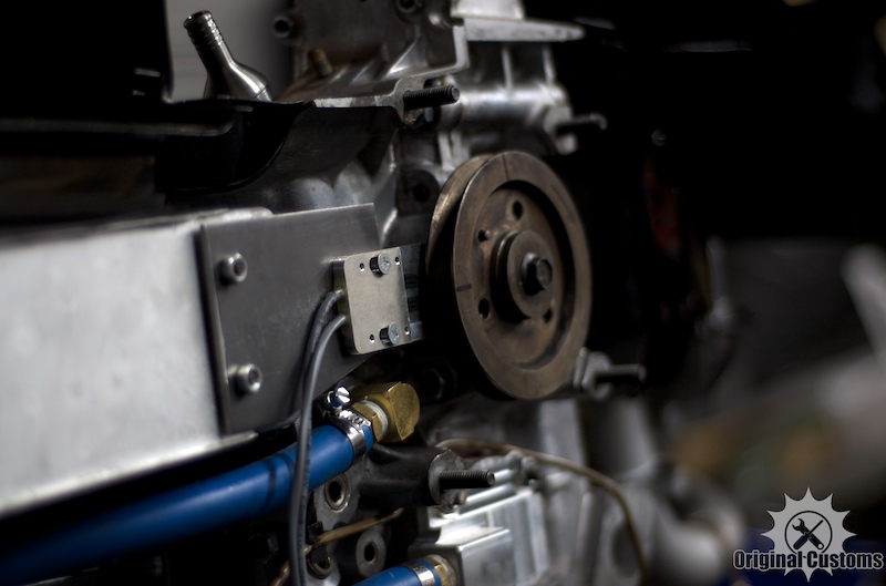
|
|
|
|
| draganc |
Feb 19 2011, 10:23 PM
Post
#11
|
|
Senior Member Group: Members Posts: 725 Joined: 2-November 09 From: central new jersey Member No.: 11,000 Region Association: North East States |
Randal sorry for the highjack and thank you Mark for your input and pic.
See attached the bracket that I’m working on for a VR sensor set-up. This would bold between the engine and the fan housing. The fan housing mounting points will need to be milled down for the thickness of the bracket. Dragan PS: My rear valence is about 25” of the ground and a used a HF lift table to rest and remove the engine. It's been like this for more then a year (IMG:style_emoticons/default/sad.gif) 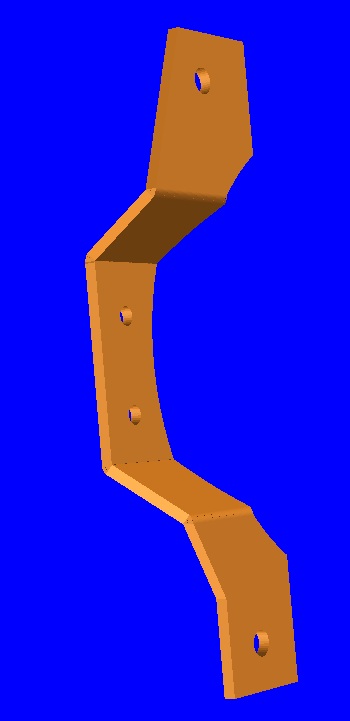 |
|
|
|
| J P Stein |
Feb 20 2011, 09:06 AM
Post
#12
|
|
Irrelevant old fart Group: Members Posts: 8,797 Joined: 30-December 02 From: Vancouver, WA Member No.: 45 Region Association: None |
I spent 10-12 winters under my 914. I hate jackstands....don't trust em', never will....so I made some alternatives at the get go and never regretted it.
An added plus is their usefullness for other stuff.......worked for Mr.2 also. Plenty of room to move around under there. Attached thumbnail(s) 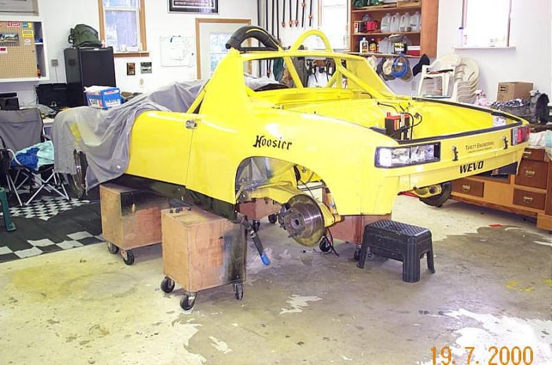
|
|
|
|
| grantsfo |
Feb 23 2011, 03:34 PM
Post
#13
|
|
Arrrrhhhh! Group: Members Posts: 4,327 Joined: 16-March 03 Member No.: 433 Region Association: None |
Man you guys are fancy. I remember my 914 first engine install 28 years ago was on old floor jack with a piece of plywood on top with car resting on cement blocks.
Of course with Boxster got a little more creative. This post has been edited by grantsfo: Feb 23 2011, 03:39 PM Attached image(s) 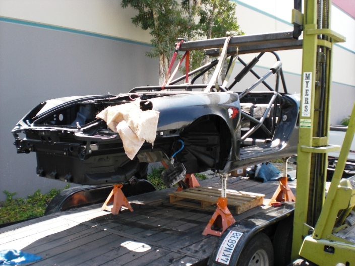
|
|
|
|
| Randal |
Feb 23 2011, 07:01 PM
Post
#14
|
|
Advanced Member Group: Members Posts: 4,446 Joined: 29-May 03 From: Los Altos, CA Member No.: 750 |
QUOTE(J P Stein @ Feb 20 2011, 07:06 AM) I spent 10-12 winters under my 914. I hate jackstands....don't trust em', never will....so I made some alternatives at the get go and never regretted it. An added plus is their usefullness for other stuff.......worked for Mr.2 also. Plenty of room to move around under there. Are those 3/4 plywood boxes JP? How high? That will be my next project down at my buddies stair company. |
|
|
|
| J P Stein |
Feb 23 2011, 08:57 PM
Post
#15
|
|
Irrelevant old fart Group: Members Posts: 8,797 Joined: 30-December 02 From: Vancouver, WA Member No.: 45 Region Association: None |
Without going out to my cold garage, I recall they are made out of a basic 16 inch max cut.......rip a 4 X 8 plywood sheet into 3 ea.16 inch wide strips....less the kerf.
This makes 18, 16 inch (approx) squares. Inside each box is a X cross brace top to bottom & 2X2s in the corners. Screw & glue the whole works together, some HF swivel casters and ya have 3 boxes.....less the X brace which requires more wood. IIRC, it took 2 sheets of 3/4 plywood. They stand about 22-23 inches tall with the casters......IIRC. It's snowing intermittently & I'm staying in the warm house. The 16 inch squares go at the top & bottom and the rest get trimmed to fit as required. When your done you'll have a BS degree in plywood management. (IMG:style_emoticons/default/biggrin.gif) They are stout. Attached image(s) 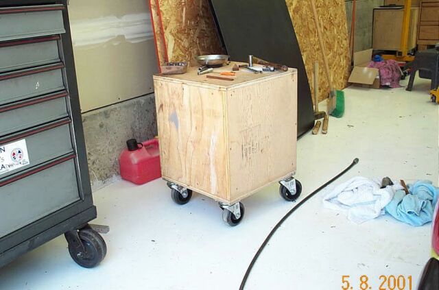
|
|
|
|
| Randal |
Feb 24 2011, 10:08 AM
Post
#16
|
|
Advanced Member Group: Members Posts: 4,446 Joined: 29-May 03 From: Los Altos, CA Member No.: 750 |
QUOTE(J P Stein @ Feb 23 2011, 06:57 PM) Without going out to my cold garage, I recall they are made out of a basic 16 inch max cut.......rip a 4 X 8 plywood sheet into 3 ea.16 inch wide strips....less the kerf. This makes 18, 16 inch (approx) squares. Inside each box is a X cross brace top to bottom & 2X2s in the corners. Screw & glue the whole works together, some HF swivel casters and ya have 3 boxes.....less the X brace which requires more wood. IIRC, it took 2 sheets of 3/4 plywood. They stand about 22-23 inches tall with the casters......IIRC. It's snowing intermittently & I'm staying in the warm house. The 16 inch squares go at the top & bottom and the rest get trimmed to fit as required. When your done you'll have a BS degree in plywood management. (IMG:style_emoticons/default/biggrin.gif) They are stout. I'll bet they are stout. When it gets warm enough to make the garage trip please show a picture of how you did the X brace. Thanks. |
|
|
|
| J P Stein |
Feb 24 2011, 10:44 AM
Post
#17
|
|
Irrelevant old fart Group: Members Posts: 8,797 Joined: 30-December 02 From: Vancouver, WA Member No.: 45 Region Association: None |
QUOTE(Randal @ Feb 24 2011, 08:08 AM) I'll bet they are stout. When it gets warm enough to make the garage trip please show a picture of how you did the X brace. Thanks. The braces are permanently enclosed in the boxes so discription will have to do. Once you have the 4 sides on the bottom of your box, measure the inside width.....prolly around 14-1/2 inches. Rip 2 of your 16 inch squares to that width. Find the center of that width & layout a 3/4 ( actually 11/16 cause 3/4 ply ain't) inch slot X 8 inches deep & centered on that CL. Cut it out on 2 pieces and shove them together.....slot to slot (tight fits are gud)....now you have an X brace. A couple 2 X 2s where they join for screwing/glueing purposes makes em' solid and locked within the box. One needs a good table saw with an accurate fence.....a cabniet shop is the perfect place to find one. I built mine.......the build discription would run to pages if I could remember how I did it. (IMG:style_emoticons/default/confused24.gif) WAG bout 6-700 lbs.....but it's on casters. (IMG:style_emoticons/default/biggrin.gif) We ended up with 3-4 inches of snow last night so I'm taking vacation today.....to shovel my steep driveway clear.....bummer. Attached thumbnail(s) 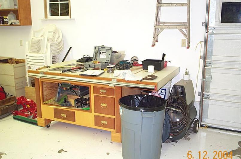
|
|
|
|
| Randal |
Feb 25 2011, 10:12 PM
Post
#18
|
|
Advanced Member Group: Members Posts: 4,446 Joined: 29-May 03 From: Los Altos, CA Member No.: 750 |
QUOTE(J P Stein @ Feb 24 2011, 08:44 AM) QUOTE(Randal @ Feb 24 2011, 08:08 AM) I'll bet they are stout. When it gets warm enough to make the garage trip please show a picture of how you did the X brace. Thanks. The braces are permanently enclosed in the boxes so discription will have to do. Once you have the 4 sides on the bottom of your box, measure the inside width.....prolly around 14-1/2 inches. Rip 2 of your 16 inch squares to that width. Find the center of that width & layout a 3/4 ( actually 11/16 cause 3/4 ply ain't) inch slot X 8 inches deep & centered on that CL. Cut it out on 2 pieces and shove them together.....slot to slot (tight fits are gud)....now you have an X brace. A couple 2 X 2s where they join for screwing/glueing purposes makes em' solid and locked within the box. One needs a good table saw with an accurate fence.....a cabniet shop is the perfect place to find one. I built mine.......the build discription would run to pages if I could remember how I did it. (IMG:style_emoticons/default/confused24.gif) WAG bout 6-700 lbs.....but it's on casters. (IMG:style_emoticons/default/biggrin.gif) We ended up with 3-4 inches of snow last night so I'm taking vacation today.....to shovel my steep driveway clear.....bummer. That is a real work of art JP. I really miss having my table saw with the professional fence. Great tool. |
|
|
|
| Randal |
Feb 25 2011, 10:15 PM
Post
#19
|
|
Advanced Member Group: Members Posts: 4,446 Joined: 29-May 03 From: Los Altos, CA Member No.: 750 |
The next phase of the installation begins tomorrow.
Have to sort out the electrics and finish tying together the oiling system. Pretty exciting. (IMG:style_emoticons/default/smile.gif) Of course if this storm decides to hit tomorrow morning all will be put on hold as I have less room, in my garage, than anyone else on the planet. |
|
|
|
| J P Stein |
Feb 26 2011, 09:18 AM
Post
#20
|
|
Irrelevant old fart Group: Members Posts: 8,797 Joined: 30-December 02 From: Vancouver, WA Member No.: 45 Region Association: None |
My outside thermometer says 16F this morning........
|
|
|
|
|
1 User(s) are reading this topic (1 Guests and 0 Anonymous Users)
0 Members:

|
Lo-Fi Version | Time is now: 29th April 2024 - 01:58 AM |
Invision Power Board
v9.1.4 © 2024 IPS, Inc.