|
|
|
Porsche, and the Porsche crest are registered trademarks of Dr. Ing. h.c. F. Porsche AG.
This site is not affiliated with Porsche in any way. Its only purpose is to provide an online forum for car enthusiasts. All other trademarks are property of their respective owners. |
|
|

  |

| jabberwocky |
 Apr 14 2011, 08:30 AM Apr 14 2011, 08:30 AM
Post
#1
|
|
Newbie  Group: Members Posts: 40 Joined: 24-April 10 From: Cleveland OH Member No.: 11,653 Region Association: None |
Just wanted to start tracking my MS conversion on my teener. I had the car running to well last year so I needed a challenge goal is to have everything finished and start tuning by mid may when driving starts getting nice around here.
I also am keeping the sock FI until I get this all running for a quick swap back. I am really excited about running fuel and spark with the MS extra code. Just for those that were wondering the stock FI worked OK but it was not exactly optimal for my frakenstien engine i was having surges and the like and could never track down a vacuum leak in my spaghetti of old hoses. Right now I have a 1.7 block 1.8 bus pistons hydrolic cam and lifters. I have a great looking spare 1.7 block and a 2.0 crank so I am looking at building a 2056 or larger down the road depending on funds. Conversion Planning Ordered and assembled Megasquirt I with v3.0 board * completed* Reflashed with megasquirt extra *Completed* Read and reread MS manual and MS extra manual *completed* Design and fabrication of new intake and plenum *in progress* Ordered needed accessories, air sensor, Narrow O2 sensor *completed* Wide band O2 *desired* (just need to sell some things first) Wiring Harness *in progress* MS mounting behind passenger seat MS working fuel with Craine 700 optical ignition working spark *first test* Future upgrades MS Working single coil with locked distributer Installation of 36-1 on crank to run coil pack Now some progress 16guage steel construction 6x3x4" box using the standard GM air temp sensor Hundai Trottle body and Idle valve I have about 4 sets of spair 914 fuel injection rails and intate assemblys so I am going to cut one slightly shorter and weld connecting tubes onto the plenum box and have the connecting hoses a little furter from the plenum The runners are essentially 1" ID pipe so that made them easy to match Box will have a bracket on the bottom that mounts the same as the OEM plenum. I went with a new box as I was replacing all of the senors and wanted a clean engine bay. I may also look at forced induction in the future but right now and until im running good I am staying N/A. Attached image(s) 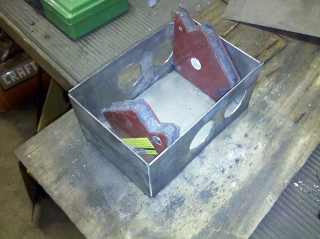 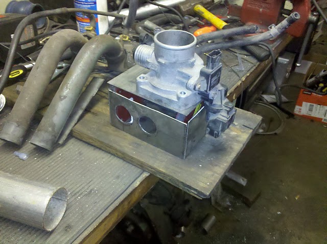 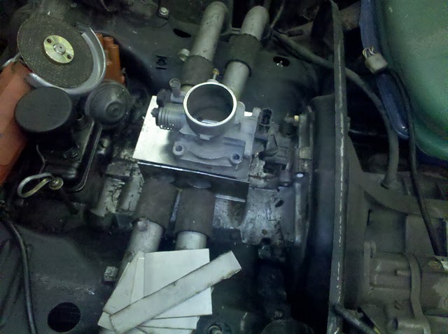
|
   |

 
|
| Loser_Cruiser |
Apr 14 2011, 11:34 AM
Post
#2
|
|
Member Group: Members Posts: 407 Joined: 4-April 05 From: Bellingham, WA Member No.: 3,873 Region Association: Pacific Northwest |
Keep it up! I'm looking to do a ms conversion on my type 4 beetle conversion.
|
|
|
|
| r_towle |
Apr 14 2011, 12:00 PM
Post
#3
|
|
Custom Member Group: Members Posts: 24,574 Joined: 9-January 03 From: Taxachusetts Member No.: 124 Region Association: North East States |
did you use any formula to determine the size of the plenum?
Rich |
|
|
|
| jabberwocky |
Apr 14 2011, 12:24 PM
Post
#4
|
|
Newbie Group: Members Posts: 40 Joined: 24-April 10 From: Cleveland OH Member No.: 11,653 Region Association: None |
QUOTE(r_towle @ Apr 14 2011, 02:00 PM)  did you use any formula to determine the size of the plenum? Rich Rich, I did then gave up then I just took a WAG I started looking at formulas for plenum volume formula and found all sorts of black art. 1.5X runner volume was one that came up fairly regularly. 914 has 4 runners 1" diameter by about 12" in lenght so about 56 cubic inches Mine is 72cubic inches just under 2x runner volume. I also came across with FI The largest you can make is the best " I believe this for WOT but in all other cases I believe an huge plenum would make throttle response very interesting. In the end I made it square so that it could be mounted easily to the engine block and I could easily mount to the throttle body and the runners. I made one similar in size to the stock but I know my internal volume is larger. Once I get it running I may play with other designs and sizes This design will cost me less than15$ in raw material and about a day to fab. So if it is a real dog I can change it but I believe the plenum size will not play a large roll and I will be similar to stock. |
|
|
|
| rohar |
Apr 14 2011, 01:01 PM
Post
#5
|
|
Senior Member Group: Members Posts: 924 Joined: 25-October 08 From: spokane Member No.: 9,685 Region Association: None |
Did you think of using a bolt on top plate for the manifold? That way you can swap out the throttle for something larger/smaller/something with progressive butterflys later and only have to fab up one new piece of metal.
|
|
|
|
| jabberwocky |
Apr 14 2011, 01:45 PM
Post
#6
|
|
Newbie Group: Members Posts: 40 Joined: 24-April 10 From: Cleveland OH Member No.: 11,653 Region Association: None |
QUOTE(rohar @ Apr 14 2011, 03:01 PM) Did you think of using a bolt on top plate for the manifold? That way you can swap out the throttle for something larger/smaller/something with progressive butterflys later and only have to fab up one new piece of metal. I did think about that and may still do it. The top will be the last piece installed I am thinking of putting in 90degree angle around the inside lip and using the bolt on option The trick with the bolt on top option will be to make sure the surfaces match, and having enough bolt coverage to ensure I do not have any leaks. Gasket material only goes so far. I think I may need thicker gauge steel for the top If I go this route as I would not want to warp the plate trying to get a sealing surface. |
|
|
|
| bam914 |
Apr 14 2011, 02:39 PM
Post
#7
|
|
Member Group: Members Posts: 334 Joined: 23-November 03 From: Atlanta, Ga Member No.: 1,378 Region Association: None |
You are going to want to radius the tubes in the plenum. Without that it will flow a lot less air.
|
|
|
|
| jabberwocky |
Apr 14 2011, 03:28 PM
Post
#8
|
|
Newbie Group: Members Posts: 40 Joined: 24-April 10 From: Cleveland OH Member No.: 11,653 Region Association: None |
QUOTE(bam914 @ Apr 14 2011, 04:39 PM) You are going to want to radius the tubes in the plenum. Without that it will flow a lot less air. Can you explain what you mean by "radius the tubes in the plenum"? |
|
|
|
| Dave_Darling |
Apr 14 2011, 05:47 PM
Post
#9
|
|
914 Idiot Group: Members Posts: 14,984 Joined: 9-January 03 From: Silicon Valley / Kailua-Kona Member No.: 121 Region Association: Northern California |
Take a velocity stack and insert it from the inside of the plenum, with the bottom of the stack sticking out and the bell of the stack toward the inside of the plenum. That's pretty much what he meant.
I have seen plena (that's the plural of plenum, at least to me right now (IMG:style_emoticons/default/wink.gif) ) that actually have trumpet-like shapes sticking up from the walls of the plenum. It sounds like Blake was suggesting having the tops of the trumpet flush with the walls of the plenum, but you could go the other way too. Lots of stuff to experiment with! --DD |
|
|
|
| biggy72 |
Apr 14 2011, 07:04 PM
Post
#10
|
|
Member Group: Members Posts: 209 Joined: 14-January 06 From: Olympia, WA Member No.: 5,418 Region Association: Pacific Northwest |
You'll have to pay for shipping from Australia, but this place has some awesome spun velocity stacks:
http://www.velocity-of-sound.com/ |
|
|
|
| jabberwocky |
Apr 15 2011, 06:51 AM
Post
#11
|
|
Newbie Group: Members Posts: 40 Joined: 24-April 10 From: Cleveland OH Member No.: 11,653 Region Association: None |
Ok, I get the picture
I will have to experiment with flaring the tubes into the plenum. I believe I have some old velocity stacks from a set of IDF's laying around I could play with. |
|
|
|
| biggy72 |
Apr 15 2011, 07:40 AM
Post
#12
|
|
Member Group: Members Posts: 209 Joined: 14-January 06 From: Olympia, WA Member No.: 5,418 Region Association: Pacific Northwest |
Also make sure that the walls are fairly stiff on the intake. I've had a couple that flexed quited a bit and it's really hard to tune a variable volume intake running on manifold pressure.
|
|
|
|
| jabberwocky |
Apr 17 2011, 03:55 PM
Post
#13
|
|
Newbie Group: Members Posts: 40 Joined: 24-April 10 From: Cleveland OH Member No.: 11,653 Region Association: None |
Ok Little more progress
Started welding box assembly together. I cut down a set of runners and templated my placement into the box. Then welded the box together. to make it flow a little better I "flared" the ends of the tubes inside the box to simulate velocity stacks. I fited in on the top of the engine and It looks good. Took out the seats started to rout my harness and placed the MS unit found rust under the seats (IMG:style_emoticons/default/headbang.gif) then got side tracked with removing cancer in my hell hole and under the drivers seat. I have the hell hole cleanded up nicely now I just need to fab up some plates and weld them in. Anyone have any threads explaining good techniques for welding in that tight area. I am going to attack the problem from both above and below that area for reinforcment. Going to use 16 guage steel. first make a stiff card paper template then bend and place plate in place. For the seat repair I am just going to cut out the rusted area grind back to clean mettal every where else and weld in the areas I cut out. |
|
|
|
| jabberwocky |
Apr 17 2011, 04:01 PM
Post
#14
|
|
Newbie Group: Members Posts: 40 Joined: 24-April 10 From: Cleveland OH Member No.: 11,653 Region Association: None |
Pictures
Attached image(s) 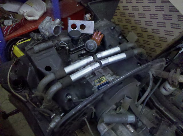 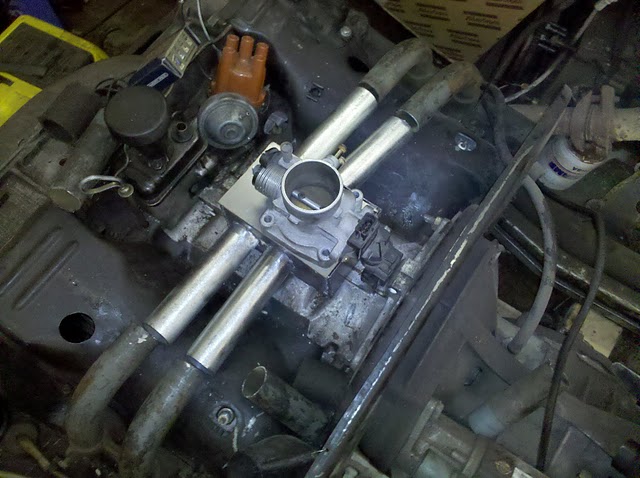 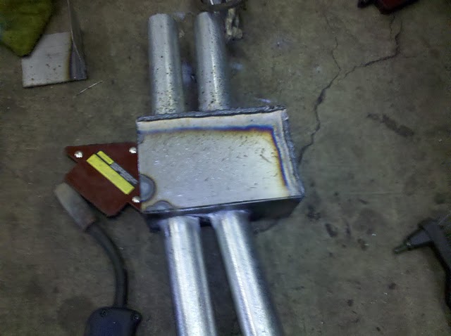 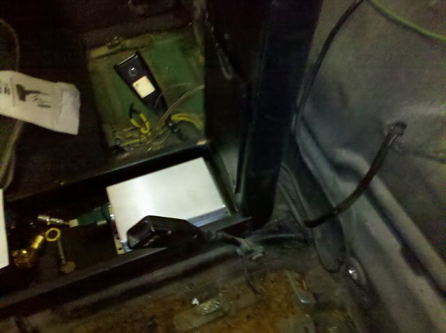
|
|
|
|
| 904svo |
Apr 17 2011, 07:10 PM
Post
#15
|
|
904SVO Group: Members Posts: 1,118 Joined: 17-November 05 From: Woodstock,Georgia Member No.: 5,146 |
I hope you tested it for leaks!!
|
|
|
|
| 1973_1.7 |
May 22 2011, 10:34 AM
Post
#16
|
|
Newbie Group: Members Posts: 19 Joined: 9-September 09 From: Norway Member No.: 10,784 Region Association: Europe |
Any updates?
|
|
|
|
|
1 User(s) are reading this topic (1 Guests and 0 Anonymous Users)
0 Members:

|
Lo-Fi Version | Time is now: 13th May 2024 - 10:37 PM |
Invision Power Board
v9.1.4 © 2024 IPS, Inc.