|
|
|
Porsche, and the Porsche crest are registered trademarks of Dr. Ing. h.c. F. Porsche AG.
This site is not affiliated with Porsche in any way. Its only purpose is to provide an online forum for car enthusiasts. All other trademarks are property of their respective owners. |
|
|

  |

| Prospectfarms |
 Jun 30 2011, 06:34 AM Jun 30 2011, 06:34 AM
Post
#1
|
|
Member  Group: Members Posts: 495 Joined: 7-March 11 From: Louisville, KY Member No.: 12,801 Region Association: Upper MidWest |
My AAR was dead. Not only that but it shorted out and ruinined my ignition harness. The hot lead coming from underneath the unit lost its insulation. The valve and the heating element were both inoperable. Here's how I fixed it.
The AAR is a can holding a spring. The spring is really a bi-metal strip curled to resemble a watch spring. It serves as a thermostat. A valve on top of the can is regulated by that spring. The valve admits "auxillary air" to the manifold. I opened the can by first cutting slots across the top of the "lip." I used a pneumatic cut-off saw. You could use anything that cuts metal. As you can see I was not very careful and it turned out alright. Opening the can separates it from the valve and exposes the spring. Tow screws are attached to the spring. The one on the side is the adjustment. It is self-explanatory given that it controls where the opening of the valve is in relation to the spring. The other screw retains the spring to the valve shaft. It provides a handy place to put a small screw driver so you can turn the valve back and forth. I loaded the valve with penetrating oil. I had to remove the spring to really work it until the valve turned smoothly. The spring comes on and off easily. There is a tiny cotter pin holding the shaft in place, but you don't have to remove it. 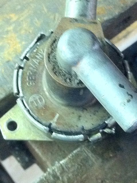 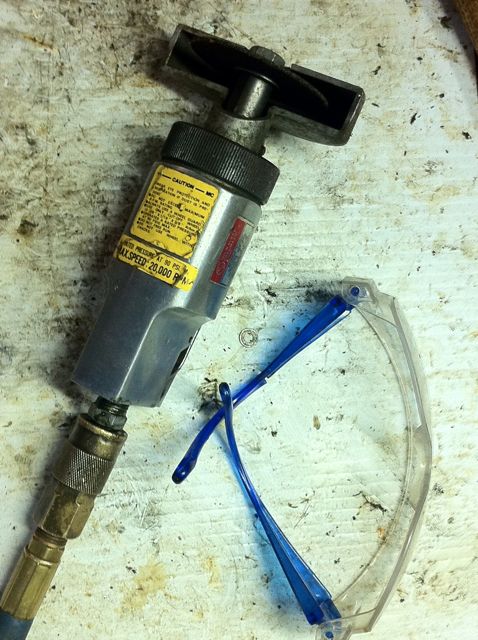 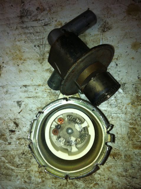 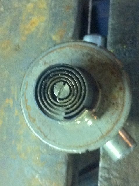 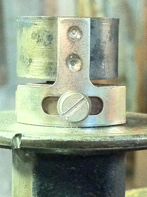 Excuse the duplicate photo. Next... Attached image(s) 
|
   |

 
|
| Prospectfarms |
Jun 30 2011, 06:42 AM
Post
#2
|
|
Member Group: Members Posts: 495 Joined: 7-March 11 From: Louisville, KY Member No.: 12,801 Region Association: Upper MidWest |
II
Next I addressed the heating element in a ceramic fixture riveted to the bottom of the can. Drill the rivet out, as wall as the two terminal rivets for the heating element. Take it all out. I put a couple of holes in the side of the can to run a positive and negative lead. I didn't want any wires underneath the can to get pinched when you screw it to the engine. I had some resistors in a shoebox in my garage. I eyeballed a couple and soldered them together. Long lead is positive. If you want to precisely duplicate the heating element -- good luck. Dave Darling recommends 120 ohms. I can't argue with him. The resistors in the bottom of the ceramic cup are a tight fit. I grounded them through the bottom hole and applied a dollop of solder to the negative lead from the outside. The positive wire is routed out through one of the holes in the side. No problem, but it took to long to adjust the resistors so they wouldn't interfere with the spring when I put everything back together. I decided to try another way.... 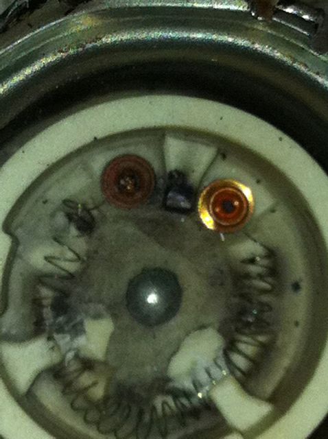 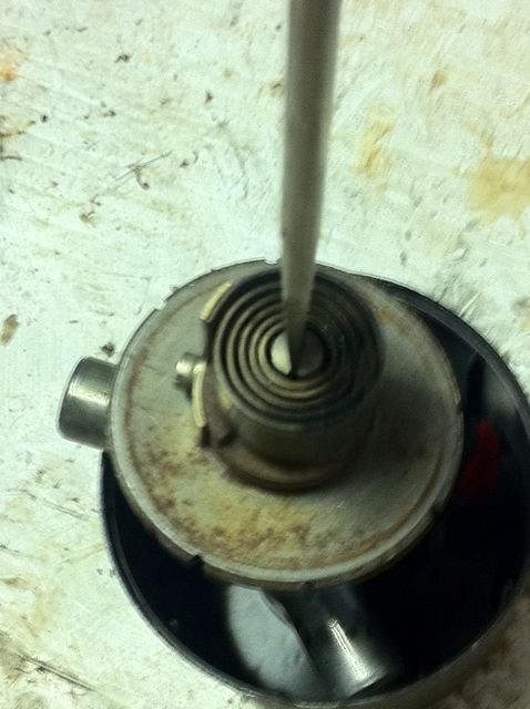 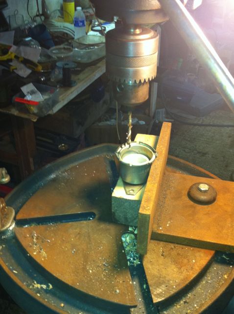 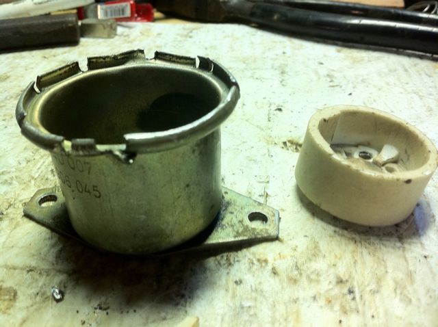 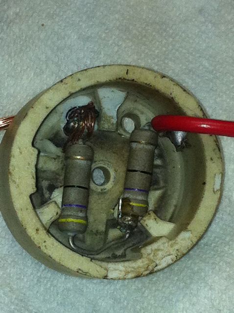 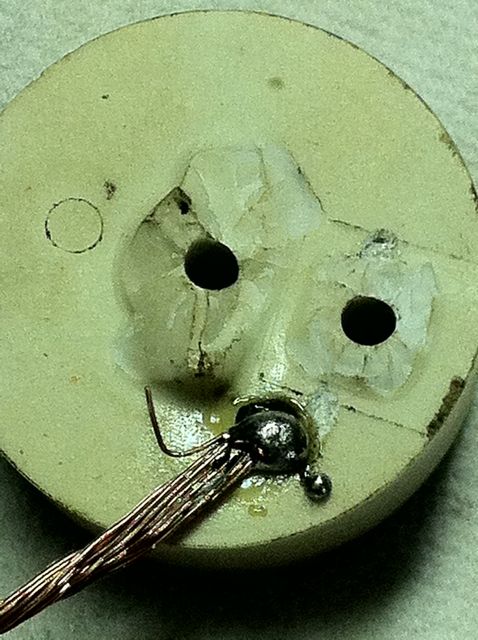 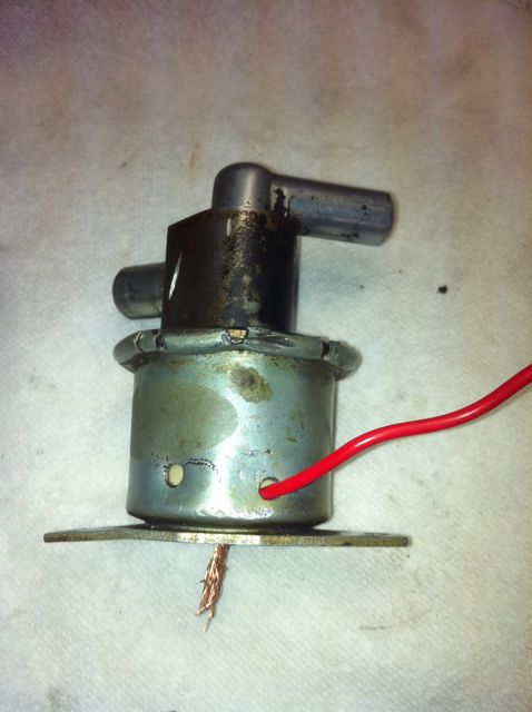 |
|
|
|
| Prospectfarms |
Jun 30 2011, 06:47 AM
Post
#3
|
|
Member Group: Members Posts: 495 Joined: 7-March 11 From: Louisville, KY Member No.: 12,801 Region Association: Upper MidWest |
III
I soldered another beefier resistor to insulated wires and ran these out the holes I'd drilled in the side of the can. I tested the assembly to make sure it put out heat. It did. Then a smeared a dab of RTV all over the positive terminal This fixed the resistor and insulated the hot side. An extra benefit to cutting slots in the lip of the can is they make it easy to realign the top with the bottom. A big pair of channel locks squeezes the lip back onto the cover. It's not a tight fit so two "tacks" of solder hold it. Note the acid core solder, it is essential for joining steel. That's it. it works fine. Open when cold, closed when warm. The resistor gets it warm enough to close tight in about 10 minutes. I've not tested the operating time attached to an engine at start up. 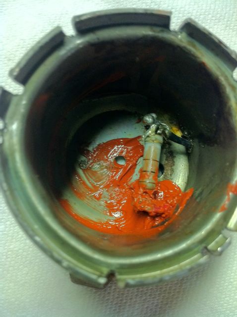 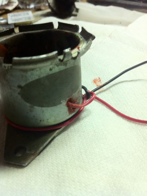 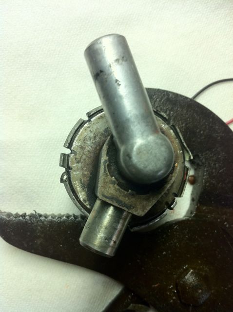 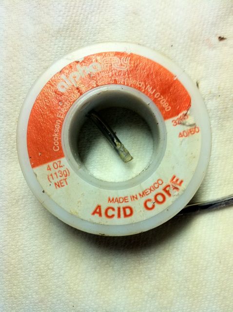 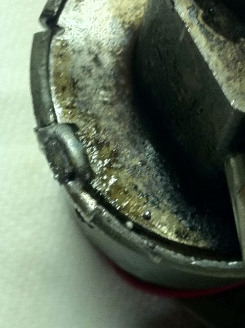 |
|
|
|
| jim_hoyland |
Jun 30 2011, 07:03 AM
Post
#4
|
|
Get that VIN ? Group: Members Posts: 9,286 Joined: 1-May 03 From: Sunset Beach, CA Member No.: 643 Region Association: Southern California |
Great write up ! (IMG:style_emoticons/default/smile.gif) Do the resisters determine how long it takes for the AAR to close ?
|
|
|
|
| Prospectfarms |
Jun 30 2011, 07:19 AM
Post
#5
|
|
Member Group: Members Posts: 495 Joined: 7-March 11 From: Louisville, KY Member No.: 12,801 Region Association: Upper MidWest |
QUOTE(jim_hoyland @ Jun 30 2011, 09:03 AM)  Great write up ! (IMG:style_emoticons/default/smile.gif) Do the resisters determine how long it takes for the AAR to close ? Thanks! I'm not an electrician but yes, the choice of resistor determines how much heat it produces which in-turn regulates the duration of the valve by operation of the bi-metalllic (heat sensitive) spring. Hotter = faster closing of valve. Resistors limit current by producing heat. "Bigger" resistors handle higher loads and accordingly produce more heat. Other people here understand electro-magnetic things better than I. But that's enough to repair the AAR. Resistors are rated and Dave Darling has a good handle on which ones work best. I just look for one that produces heat and won't burn out after a couple of hours on a 12 volt battery charger. |
|
|
|
| Prospectfarms |
Jun 30 2011, 09:55 AM
Post
#6
|
|
Member Group: Members Posts: 495 Joined: 7-March 11 From: Louisville, KY Member No.: 12,801 Region Association: Upper MidWest |
QUOTE(jim_hoyland @ Jun 30 2011, 09:03 AM) Great write up ! (IMG:style_emoticons/default/smile.gif) Do the resisters determine how long it takes for the AAR to close ? In another thread on the AAR Dave Darling posted the following info concerning choice of resistor for this kind of project: Note the parameters are ~13 ohms of resistor rated at 1-A or better. Attention to the kind of resistor is important to obtain sufficient heat and longevity. I try to pull electronic components off of old circuit boards. You can theoretically read a resistance value from the colored bands. I just guess, but I test the resistor with a multimeter and then hook it up for a couple of hours to a 4amp battery charger to make sure it won't burn out prematurely. Here's Dave's post: You can replace the resistance wire with ~13 ohms of resistor, but make sure you use resistor(s) rated at 1A or better. And check for clearance with the other parts in there. Solder them in; one end of the resistor (or of the chain of resistors if you need to use more than one) should be fastened to the housing, the other should go THROUGH the housing to have the power wire connected to it. Or run the wire (with insulation!!) through the housing to the end of the resistor. Just make sure the power wire doesn't touch the housing, or you'll get a dead short to ground again. http://www.914world.com/bbs2/index.php?s=&...t&p=1499557 I'll add that there are all kinds of resistors and they are readily available (FI radio shack) the unit cost should be less than $2. If you do this, be sure to pick up some heat sink glue/past to help conduct heat away from the Res. and into the body of the AAR. Doing so will extend the life of the resistor. I did not, but this was really more of an experiment for me. When the Res. I used goes bad, I'll replace it using something to conduct heat better. |
|
|
|
| Prospectfarms |
Jun 30 2011, 09:56 AM
Post
#7
|
|
Member Group: Members Posts: 495 Joined: 7-March 11 From: Louisville, KY Member No.: 12,801 Region Association: Upper MidWest |
Unintentional duplication of post. Don't know how, but sorry. QUOTE(jim_hoyland @ Jun 30 2011, 09:03 AM) Great write up ! (IMG:style_emoticons/default/smile.gif) Do the resisters determine how long it takes for the AAR to close ? In another thread on the AAR Dave Darling posted the following info concerning choice of resistor for this kind of project: Note the parameters are ~13 ohms of resistor rated at 1-A or better. Attention to the kind of resistor is important to obtain sufficient heat and longevity. I try to pull electronic components off of old circuit boards. You can theoretically read a resistance value from the colored bands. I just guess, but I test the resistor with a multimeter and then hook it up for a couple of hours to a 4amp battery charger to make sure it won't burn out prematurely. Here's Dave's post: You can replace the resistance wire with ~13 ohms of resistor, but make sure you use resistor(s) rated at 1A or better. And check for clearance with the other parts in there. Solder them in; one end of the resistor (or of the chain of resistors if you need to use more than one) should be fastened to the housing, the other should go THROUGH the housing to have the power wire connected to it. Or run the wire (with insulation!!) through the housing to the end of the resistor. Just make sure the power wire doesn't touch the housing, or you'll get a dead short to ground again. http://www.914world.com/bbs2/index.php?s=&...t&p=1499557 I'll add that there are all kinds of resistors and they are readily available (FI radio shack) the unit cost should be less than $2. If you do this, be sure to pick up some heat sink glue/past to help conduct heat away from the Res. and into the body of the AAR. Doing so will extend the life of the resistor. I did not, but this was really more of an experiment for me. When the Res. I used goes bad, I'll replace it using something to conduct heat better. |
|
|
|
| Dave_Darling |
Jun 30 2011, 04:04 PM
Post
#8
|
|
914 Idiot Group: Members Posts: 14,984 Joined: 9-January 03 From: Silicon Valley / Kailua-Kona Member No.: 121 Region Association: Northern California |
Hey, cool! I don't remember the adjustment screw from when I had mine apart--but other than that, yours looks exactly the way I remember.
I actually used a flat-head screwdriver as a chisel, and hammered it into the lip that folds over the top of the can. Fold it back, and the lid comes off just like you show here. I took my inspiration from the odometer repair process; un-crimp the outer thing to remove the inner part. I don't know how critical the resistance is. If yours closes in 10 minutes, it's probably good enough. The ones that I have measured (three different 2.0 ones) were all right around 13 ohms; when you have ~14 volts on your system and then a 13 ohm resistor to ground, you will dissipate just about 1 watt of power, which is why you want at least 1A rated resistors for that. With 120 ohms, you'll dissipate less power and not need resistors rated as high. (Probably on the order of 100 mA, or 0.1 Amps?) --DD |
|
|
|
| Prospectfarms |
Jun 30 2011, 05:02 PM
Post
#9
|
|
Member Group: Members Posts: 495 Joined: 7-March 11 From: Louisville, KY Member No.: 12,801 Region Association: Upper MidWest |
QUOTE(Dave_Darling @ Jun 30 2011, 06:04 PM) Hey, cool! I don't remember the adjustment screw from when I had mine apart-- With 120 ohms, you'll dissipate less power and not need resistors rated as high. (Probably on the order of 100 mA, or 0.1 Amps?) --DD You're suggestion and advice to the board in other threads inspired me to take it apart. (not to mention poverty) "Tom" gave me a little more information about resistors. He could tell from my post that I don't understand electronics. His words: "Resisters are rated by ohmic value and wattage. Current is variable thru any sized resister depending on the voltage applied. IE: a 10 ohm resister with 10 volts applied is drawing 1 amp. with 5 volt applied is 1/2 of an amp. Power is a function of voltage applied and amperage. P=IE, where P=power, I= current, and E=voltage. For a 10 ohm resistor using a circuit voltage of 10 volts, the current is 1 amp and the power is 10 watts. Same circuit with 5 volts, amperage drops to 1/2 amp and power is 2.5 watts For more indepth electrical info, just google basic electrical theory." For this application all we care about is whether it gets hot and will last. I assume your 13 ohm resistors rated 1A or higher remain in service. |
|
|
|
|
1 User(s) are reading this topic (1 Guests and 0 Anonymous Users)
0 Members:

|
Lo-Fi Version | Time is now: 13th May 2024 - 03:11 AM |
Invision Power Board
v9.1.4 © 2024 IPS, Inc.