|
|
|
Porsche, and the Porsche crest are registered trademarks of Dr. Ing. h.c. F. Porsche AG.
This site is not affiliated with Porsche in any way. Its only purpose is to provide an online forum for car enthusiasts. All other trademarks are property of their respective owners. |
|
|


| Valy |
 Sep 3 2011, 01:38 AM Sep 3 2011, 01:38 AM
Post
#81
|
|
Senior Member  Group: Members Posts: 1,677 Joined: 6-April 10 From: Sunnyvale, CA Member No.: 11,573 Region Association: Northern California |
I got a spare engine with my car. The engine looks nice but the PO drained the oil out and left the sump open. Then he wrapped it in plastic wrap and dropped the engine on the left head so it has a nice crack.
Got myself a new pair of heads that are rebuilt right now. It's going to be a big L-Jet as I don't have the patience to deal with the old D-Jet (although I have all the parts for a D-Jet). I I'm going to make it a 2056cc unless in change my mind and go crazy with a bigger crank (IMG:style_emoticons/default/idea.gif) I started taking the engine apart and going to document as much as I can. Not my first rebuild but is my first Type4 rebuild so wish me luck! Today I got pistons 3 & 4 out. #3 looks nice, not too much signs of wear. The ring gaps are about 1mm (trash) #4 is also nice but the piston got a small bent while trying to remove the pin. That bent trapped the oil ring. Never mind, I'm going for bigger one anyway. The cylinder registers are nice. In fact, the entire case is very nice and clean. Anyone knows the meaning of the inscriptions on the cylinders and pistons? 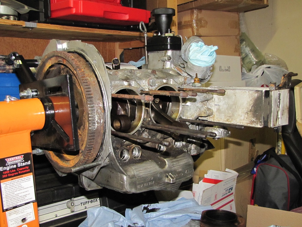 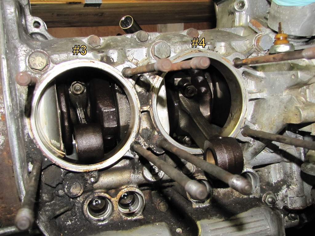 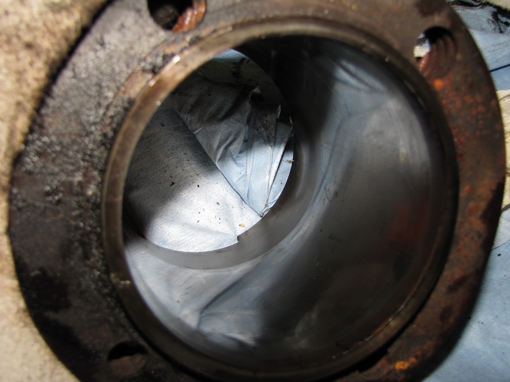 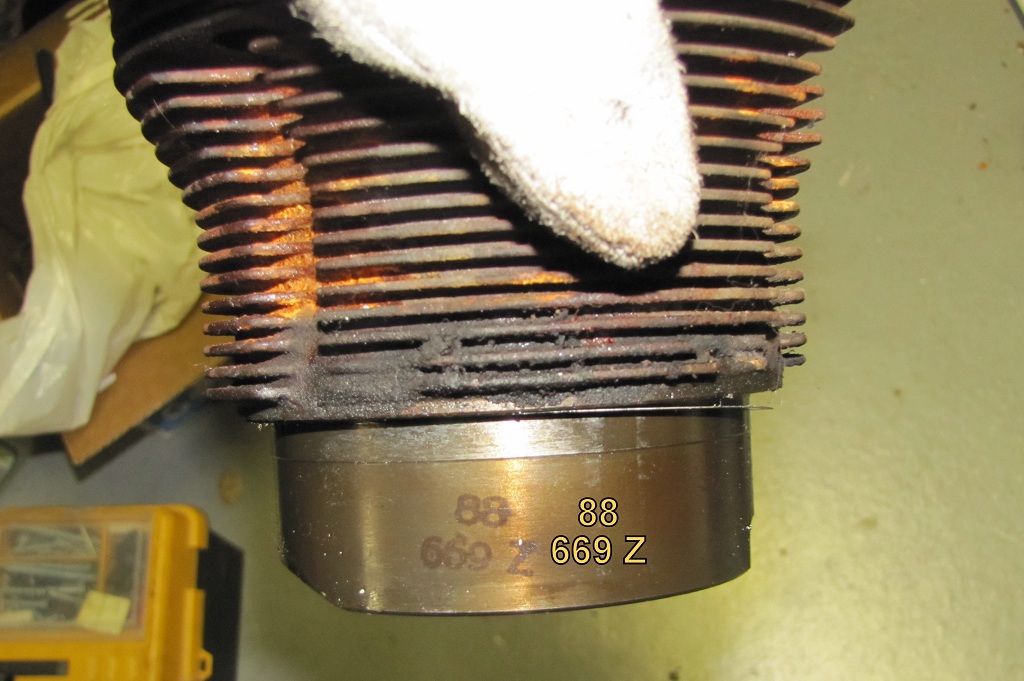 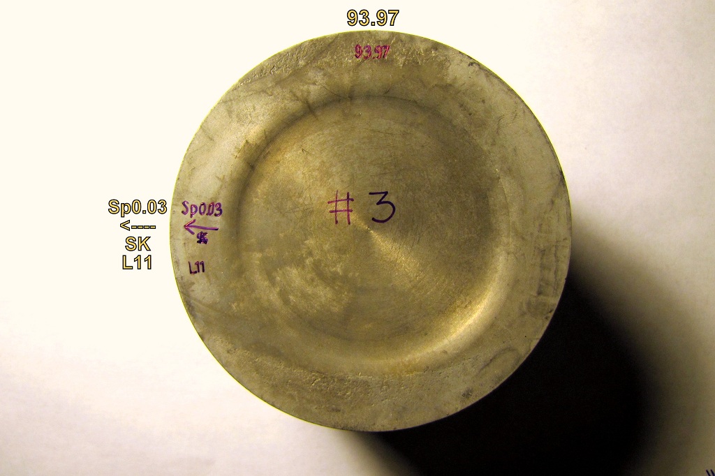 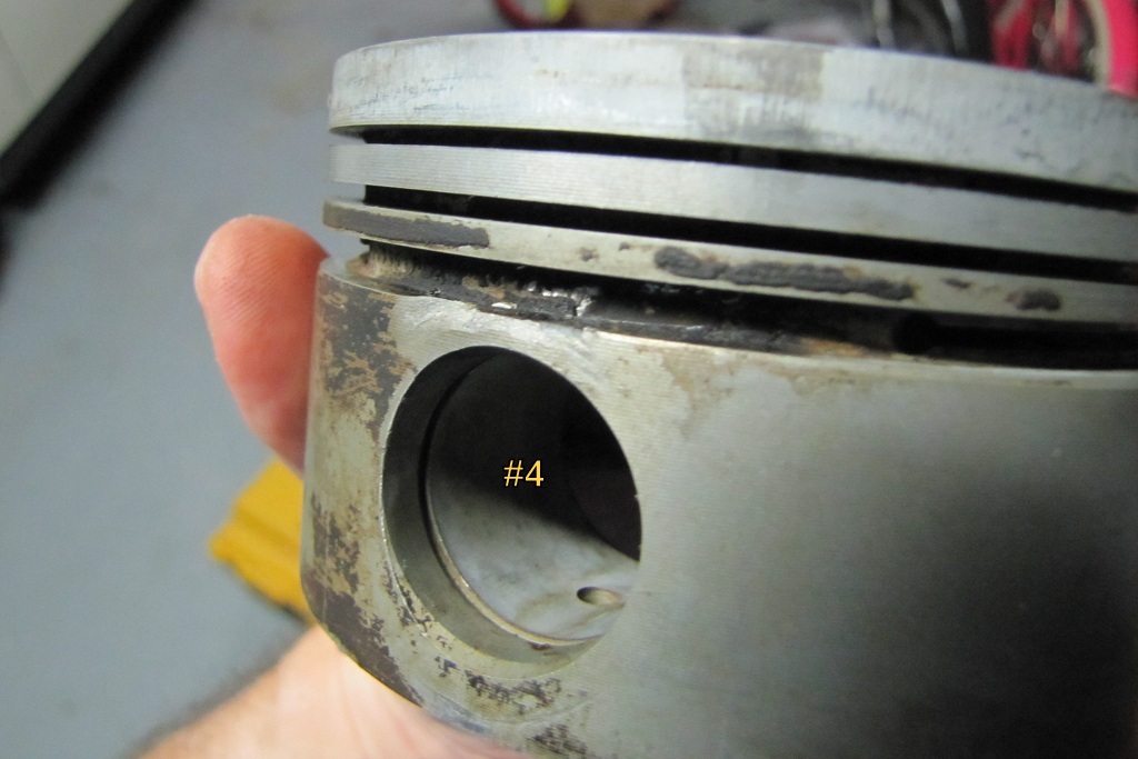 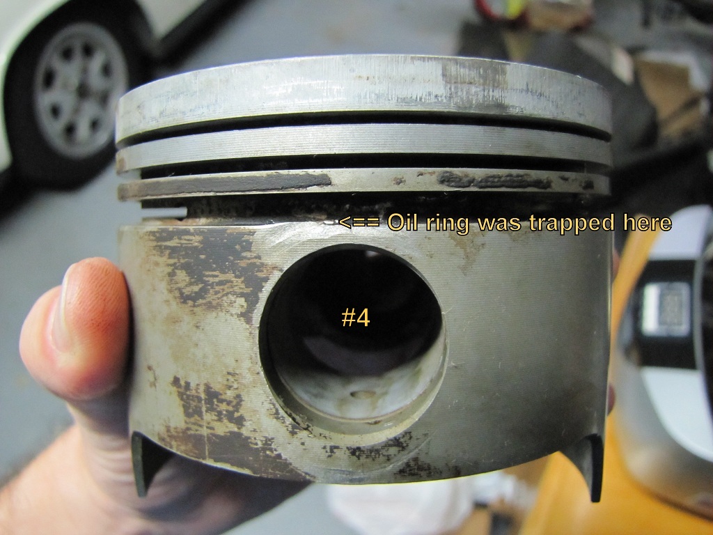 |
   |

 
|
Posts in this topic
 Valy Engine rebuild Sep 3 2011, 01:38 AM
 dlee6204 :popcorn: Sep 3 2011, 06:29 AM
 stewteral
:popcorn:
dlee6204,
WOW! That's the M... Sep 9 2011, 12:20 PM Valy
:popcorn:
dlee6204,
WOW! That's the ... Sep 9 2011, 12:30 PM r_towle
:popcorn:
dlee6204,
WOW! That's the ... Sep 9 2011, 01:58 PM Valy More work today and more surprises.
Took off cylin... Sep 4 2011, 07:47 PM Dave_Darling Piston writing: 93.97 == diameter in mm. That... Sep 4 2011, 07:54 PM bcheney
Piston writing: 93.97 == diameter in mm. That... Sep 4 2011, 09:20 PM Valy
Piston writing: 93.97 == diameter in mm. That... Sep 4 2011, 09:31 PM bcheney Well...I'm not an expert on component wear...b... Sep 4 2011, 09:38 PM Vacca Rabite Assuming you are going to put a non stock cam in t... Sep 5 2011, 07:19 AM Jake Raby Yep, retention wire wear..
But if you do this job... Sep 5 2011, 08:44 AM Valy Oil pump doesn't want to come off. I took the ... Sep 5 2011, 10:22 AM McMark Yup, use the tabs and pry it off. I'm sure so... Sep 5 2011, 10:27 AM Valy
Yup, use the tabs and pry it off. I'm sure s... Sep 5 2011, 11:00 AM Vacca Rabite
Yup, use the tabs and pry it off. I'm sure ... Sep 5 2011, 01:42 PM Cap'n Krusty
[quote name='Valy' post='1534789' date='Sep 5 201... Sep 5 2011, 01:55 PM Valy Just to make thing clear:
The engine is a 914 2.0... Sep 5 2011, 03:19 PM McMark
I don't see any comments about temperature se... Sep 5 2011, 07:21 PM Cap'n Krusty
I don't see any comments about temperature s... Sep 11 2011, 09:06 AM McMark
The temp sensor installation shown in the picture... Oct 20 2011, 02:36 PM Valy
The temp sensor installation shown in the pictur... Oct 20 2011, 07:19 PM r_towle Pry it off, be careful.
Its held in tight, and the... Sep 5 2011, 11:08 AM John Jentz Loosen some of those case nuts that surround it. ... Sep 5 2011, 01:08 PM Jake Raby Worst case pull two of the studs on one case half ... Sep 5 2011, 01:43 PM Valy Oil pump is out :Qarl:
It has some wear on the d... Sep 5 2011, 04:22 PM Jake Raby The lowermost pic of the oil pump shows a failing ... Sep 5 2011, 04:30 PM Valy
The lowermost pic of the oil pump shows a failing... Sep 5 2011, 05:15 PM jcd914
The shaft in the pump should be flush with the... Sep 5 2011, 07:14 PM jsconst
[quote name='Jake Raby' post='1534917... Sep 11 2011, 08:37 AM Jake Raby There ya have it... What I said earlier.. This hap... Sep 5 2011, 06:20 PM Valy Put all my flat screwdrivers away so I won't b... Sep 9 2011, 12:30 PM stugray Chances are you missed a bolt or two.
The case re... Sep 9 2011, 01:20 PM Valy
Chances are you missed a bolt or two.
The case r... Sep 9 2011, 01:44 PM bigkensteele
Chances are you missed a bolt or two.
The case ... Sep 9 2011, 02:01 PM Valy
Where did you get that cool billet engine stand a... Sep 9 2011, 06:21 PM Matt Meyer Splitting Case Halves Classic Thread shows bolt lo... Sep 9 2011, 01:48 PM Vacca Rabite :agree:
Pull the flywheel. There are things behin... Sep 9 2011, 04:45 PM Jake Raby Buy my damn video!! I go over every nut an... Sep 9 2011, 07:22 PM Valy
Buy my damn video!! I go over every nut a... Sep 9 2011, 07:50 PM bigkensteele
Buy my damn video!! I go over every nut a... Sep 9 2011, 07:54 PM Jake Raby
Buy my damn video!! I go over every nut ... Sep 9 2011, 07:57 PM mrdkrantz Wooden wedges and an old animal hid mallet(if you ... Sep 9 2011, 10:30 PM euro911 The last engine case we split had a ton of sealant... Sep 10 2011, 12:15 PM Valy WARNING:
Horror pictures bellow. Don't scroll ... Sep 10 2011, 10:34 PM Vacca Rabite Looks like an engine that had a lot of miles on it... Sep 11 2011, 07:23 AM Valy Crankshaft and Rod journals.
Some pictures of the... Sep 11 2011, 03:50 PM Valy Update:
My machinist finally measured the case and... Oct 14 2011, 01:40 PM Valy
Update:
My machinist finally measured the case an... Oct 14 2011, 04:21 PM SLITS The marks in the big end of the rod are from machi... Oct 14 2011, 01:46 PM Valy New stuff is starting to arrive!!! :Qa... Oct 20 2011, 01:48 PM vsg914 Is that the top left or the bottom left? :stir: Oct 20 2011, 02:51 PM Valy Those are AA pistons.
Measured the ring gaps in t... Oct 20 2011, 07:42 PM Valy Cam is here :Qarl:
Lift is 8.2mm (0.323") ... Nov 11 2011, 01:41 PM Marty Yeoman What WebCam part number is your cam? Nov 11 2011, 02:14 PM Valy
What WebCam part number is your cam?
It's a ... Nov 11 2011, 02:45 PM Marty Yeoman
What WebCam part number is your cam?
It's a... Nov 15 2011, 02:25 PM Valy
[quote name='Valy' post='1570171' date='Nov 11 20... Nov 15 2011, 03:44 PM Scarlet75 So thats not a Raby Cam? Nov 11 2011, 05:00 PM Valy
So thats not a Raby Cam?
Nope. I bought it from ... Nov 11 2011, 05:16 PM Valy Strange but true, the bolts that hold the gear on ... Nov 11 2011, 05:42 PM McMark Because the tool suppliers have cheaper prices for... Nov 11 2011, 06:57 PM Kansas 914
Because the tool suppliers have cheaper prices fo... Nov 11 2011, 07:00 PM jcd914
Because the tool suppliers have cheaper prices f... Nov 11 2011, 07:24 PM jimbot2000
[quote name='Kansas 914' post='1570296' date='Nov... Feb 20 2012, 10:07 AM worn
Because the tool suppliers have cheaper prices fo... Apr 6 2012, 08:59 AM Valy Main bearings arrived this morning.
Those are +0.... Nov 12 2011, 11:08 PM pilothyer Valy, where's the rest of the story? Feb 15 2012, 10:43 PM Valy
Valy, where's the rest of the story?
The eng... Feb 15 2012, 10:54 PM Dave_Darling Must be German Precision. That's what (almost... Feb 16 2012, 03:22 PM Valy Wow, the world was down for such a long time exact... May 15 2012, 11:43 AM Valy [u]Oil Pump
After my oil pump saga described in t... May 15 2012, 12:13 PM Valy Oil Galleys Plugs
I had the main oil galleys plug... May 15 2012, 12:50 PM Valy [u]Gaskets
I had to make a thicker gasket for my ... May 15 2012, 12:51 PM Valy Crankshaft
I re-built the crankshaft assembly.
T... May 15 2012, 12:51 PM euro911 Hey Val, is that AL pump cover plate a tad thicker... May 15 2012, 12:58 PM Valy
Hey Val, is that AL pump cover plate a tad thicke... May 15 2012, 01:07 PM Valy Connecting Rods
I had the connecting rods recondi... May 15 2012, 02:10 PM Valy One very important remark regarding rod assembly t... May 15 2012, 02:41 PM Valy [u]Camshaft
I'm using a new camshaft. This is... May 15 2012, 02:51 PM Valy [b]Oil Pressure Regulator
I had a [url=http://www... May 15 2012, 02:56 PM Valy Half Case Assembly
Mounted the distributor gear w... May 15 2012, 03:15 PM 396 Sub... keep it coming., Great write up May 16 2012, 05:15 AM Valy Windage/Baffle Plate
My core engine came without ... May 17 2012, 03:38 PM Valy Closing the Case
With the windage plate, cam bear... May 17 2012, 03:49 PM Valy [u]Type 1 Oil Pump Installation
I've been thr... May 17 2012, 04:10 PM Valy Oil Temp Sensor
I didn't like the oil temp se... May 17 2012, 06:26 PM Valy Deck Height
I set-up my dial meter to find TDC an... May 18 2012, 02:44 AM Valy Thermostat
Slow progress this weekend as I was b... May 21 2012, 02:49 PM Valy Fixing Broken a Tin Screw Hole
Some PO of this en... May 21 2012, 11:49 PM Dave_Darling That looks like it's near where the M8 hole is... May 22 2012, 12:11 AM Valy
That looks like it's near where the M8 hole i... May 22 2012, 01:29 AM McMark Nope. Dave's right... About later cases. Early... May 22 2012, 08:08 AM Valy
Nope. Dave's right... About later cases. Earl... May 22 2012, 09:28 AM McMark The thermo-time switch was moved towards the flywh... May 22 2012, 09:48 AM McMark Here's a picture of the TTS in place on a 912E... May 22 2012, 09:54 AM Valy Maybe it's a bus thing. I just double checked ... May 22 2012, 10:25 AM euro911 I've got a '75 GC case here that has the M... May 22 2012, 11:16 AM Valy I'm not planning to take the insert out. The L... May 22 2012, 12:03 PM McMark If you're running L-Jet, are you leaving off t... May 22 2012, 12:04 PM
stewteral
:popcorn:
dlee6204,
WOW! That's the M... Sep 9 2011, 12:20 PM Valy
:popcorn:
dlee6204,
WOW! That's the ... Sep 9 2011, 12:30 PM r_towle
:popcorn:
dlee6204,
WOW! That's the ... Sep 9 2011, 01:58 PM Valy More work today and more surprises.
Took off cylin... Sep 4 2011, 07:47 PM Dave_Darling Piston writing: 93.97 == diameter in mm. That... Sep 4 2011, 07:54 PM bcheney
Piston writing: 93.97 == diameter in mm. That... Sep 4 2011, 09:20 PM Valy
Piston writing: 93.97 == diameter in mm. That... Sep 4 2011, 09:31 PM bcheney Well...I'm not an expert on component wear...b... Sep 4 2011, 09:38 PM Vacca Rabite Assuming you are going to put a non stock cam in t... Sep 5 2011, 07:19 AM Jake Raby Yep, retention wire wear..
But if you do this job... Sep 5 2011, 08:44 AM Valy Oil pump doesn't want to come off. I took the ... Sep 5 2011, 10:22 AM McMark Yup, use the tabs and pry it off. I'm sure so... Sep 5 2011, 10:27 AM Valy
Yup, use the tabs and pry it off. I'm sure s... Sep 5 2011, 11:00 AM Vacca Rabite
Yup, use the tabs and pry it off. I'm sure ... Sep 5 2011, 01:42 PM Cap'n Krusty
[quote name='Valy' post='1534789' date='Sep 5 201... Sep 5 2011, 01:55 PM Valy Just to make thing clear:
The engine is a 914 2.0... Sep 5 2011, 03:19 PM McMark
I don't see any comments about temperature se... Sep 5 2011, 07:21 PM Cap'n Krusty
I don't see any comments about temperature s... Sep 11 2011, 09:06 AM McMark
The temp sensor installation shown in the picture... Oct 20 2011, 02:36 PM Valy
The temp sensor installation shown in the pictur... Oct 20 2011, 07:19 PM r_towle Pry it off, be careful.
Its held in tight, and the... Sep 5 2011, 11:08 AM John Jentz Loosen some of those case nuts that surround it. ... Sep 5 2011, 01:08 PM Jake Raby Worst case pull two of the studs on one case half ... Sep 5 2011, 01:43 PM Valy Oil pump is out :Qarl:
It has some wear on the d... Sep 5 2011, 04:22 PM Jake Raby The lowermost pic of the oil pump shows a failing ... Sep 5 2011, 04:30 PM Valy
The lowermost pic of the oil pump shows a failing... Sep 5 2011, 05:15 PM jcd914
The shaft in the pump should be flush with the... Sep 5 2011, 07:14 PM jsconst
[quote name='Jake Raby' post='1534917... Sep 11 2011, 08:37 AM Jake Raby There ya have it... What I said earlier.. This hap... Sep 5 2011, 06:20 PM Valy Put all my flat screwdrivers away so I won't b... Sep 9 2011, 12:30 PM stugray Chances are you missed a bolt or two.
The case re... Sep 9 2011, 01:20 PM Valy
Chances are you missed a bolt or two.
The case r... Sep 9 2011, 01:44 PM bigkensteele
Chances are you missed a bolt or two.
The case ... Sep 9 2011, 02:01 PM Valy
Where did you get that cool billet engine stand a... Sep 9 2011, 06:21 PM Matt Meyer Splitting Case Halves Classic Thread shows bolt lo... Sep 9 2011, 01:48 PM Vacca Rabite :agree:
Pull the flywheel. There are things behin... Sep 9 2011, 04:45 PM Jake Raby Buy my damn video!! I go over every nut an... Sep 9 2011, 07:22 PM Valy
Buy my damn video!! I go over every nut a... Sep 9 2011, 07:50 PM bigkensteele
Buy my damn video!! I go over every nut a... Sep 9 2011, 07:54 PM Jake Raby
Buy my damn video!! I go over every nut ... Sep 9 2011, 07:57 PM mrdkrantz Wooden wedges and an old animal hid mallet(if you ... Sep 9 2011, 10:30 PM euro911 The last engine case we split had a ton of sealant... Sep 10 2011, 12:15 PM Valy WARNING:
Horror pictures bellow. Don't scroll ... Sep 10 2011, 10:34 PM Vacca Rabite Looks like an engine that had a lot of miles on it... Sep 11 2011, 07:23 AM Valy Crankshaft and Rod journals.
Some pictures of the... Sep 11 2011, 03:50 PM Valy Update:
My machinist finally measured the case and... Oct 14 2011, 01:40 PM Valy
Update:
My machinist finally measured the case an... Oct 14 2011, 04:21 PM SLITS The marks in the big end of the rod are from machi... Oct 14 2011, 01:46 PM Valy New stuff is starting to arrive!!! :Qa... Oct 20 2011, 01:48 PM vsg914 Is that the top left or the bottom left? :stir: Oct 20 2011, 02:51 PM Valy Those are AA pistons.
Measured the ring gaps in t... Oct 20 2011, 07:42 PM Valy Cam is here :Qarl:
Lift is 8.2mm (0.323") ... Nov 11 2011, 01:41 PM Marty Yeoman What WebCam part number is your cam? Nov 11 2011, 02:14 PM Valy
What WebCam part number is your cam?
It's a ... Nov 11 2011, 02:45 PM Marty Yeoman
What WebCam part number is your cam?
It's a... Nov 15 2011, 02:25 PM Valy
[quote name='Valy' post='1570171' date='Nov 11 20... Nov 15 2011, 03:44 PM Scarlet75 So thats not a Raby Cam? Nov 11 2011, 05:00 PM Valy
So thats not a Raby Cam?
Nope. I bought it from ... Nov 11 2011, 05:16 PM Valy Strange but true, the bolts that hold the gear on ... Nov 11 2011, 05:42 PM McMark Because the tool suppliers have cheaper prices for... Nov 11 2011, 06:57 PM Kansas 914
Because the tool suppliers have cheaper prices fo... Nov 11 2011, 07:00 PM jcd914
Because the tool suppliers have cheaper prices f... Nov 11 2011, 07:24 PM jimbot2000
[quote name='Kansas 914' post='1570296' date='Nov... Feb 20 2012, 10:07 AM worn
Because the tool suppliers have cheaper prices fo... Apr 6 2012, 08:59 AM Valy Main bearings arrived this morning.
Those are +0.... Nov 12 2011, 11:08 PM pilothyer Valy, where's the rest of the story? Feb 15 2012, 10:43 PM Valy
Valy, where's the rest of the story?
The eng... Feb 15 2012, 10:54 PM Dave_Darling Must be German Precision. That's what (almost... Feb 16 2012, 03:22 PM Valy Wow, the world was down for such a long time exact... May 15 2012, 11:43 AM Valy [u]Oil Pump
After my oil pump saga described in t... May 15 2012, 12:13 PM Valy Oil Galleys Plugs
I had the main oil galleys plug... May 15 2012, 12:50 PM Valy [u]Gaskets
I had to make a thicker gasket for my ... May 15 2012, 12:51 PM Valy Crankshaft
I re-built the crankshaft assembly.
T... May 15 2012, 12:51 PM euro911 Hey Val, is that AL pump cover plate a tad thicker... May 15 2012, 12:58 PM Valy
Hey Val, is that AL pump cover plate a tad thicke... May 15 2012, 01:07 PM Valy Connecting Rods
I had the connecting rods recondi... May 15 2012, 02:10 PM Valy One very important remark regarding rod assembly t... May 15 2012, 02:41 PM Valy [u]Camshaft
I'm using a new camshaft. This is... May 15 2012, 02:51 PM Valy [b]Oil Pressure Regulator
I had a [url=http://www... May 15 2012, 02:56 PM Valy Half Case Assembly
Mounted the distributor gear w... May 15 2012, 03:15 PM 396 Sub... keep it coming., Great write up May 16 2012, 05:15 AM Valy Windage/Baffle Plate
My core engine came without ... May 17 2012, 03:38 PM Valy Closing the Case
With the windage plate, cam bear... May 17 2012, 03:49 PM Valy [u]Type 1 Oil Pump Installation
I've been thr... May 17 2012, 04:10 PM Valy Oil Temp Sensor
I didn't like the oil temp se... May 17 2012, 06:26 PM Valy Deck Height
I set-up my dial meter to find TDC an... May 18 2012, 02:44 AM Valy Thermostat
Slow progress this weekend as I was b... May 21 2012, 02:49 PM Valy Fixing Broken a Tin Screw Hole
Some PO of this en... May 21 2012, 11:49 PM Dave_Darling That looks like it's near where the M8 hole is... May 22 2012, 12:11 AM Valy
That looks like it's near where the M8 hole i... May 22 2012, 01:29 AM McMark Nope. Dave's right... About later cases. Early... May 22 2012, 08:08 AM Valy
Nope. Dave's right... About later cases. Earl... May 22 2012, 09:28 AM McMark The thermo-time switch was moved towards the flywh... May 22 2012, 09:48 AM McMark Here's a picture of the TTS in place on a 912E... May 22 2012, 09:54 AM Valy Maybe it's a bus thing. I just double checked ... May 22 2012, 10:25 AM euro911 I've got a '75 GC case here that has the M... May 22 2012, 11:16 AM Valy I'm not planning to take the insert out. The L... May 22 2012, 12:03 PM McMark If you're running L-Jet, are you leaving off t... May 22 2012, 12:04 PM  |
1 User(s) are reading this topic (1 Guests and 0 Anonymous Users)
0 Members:

|
Lo-Fi Version | Time is now: 1st May 2026 - 01:38 PM |
Invision Power Board
v9.1.4 © 2026 IPS, Inc.