|
|
|
Porsche, and the Porsche crest are registered trademarks of Dr. Ing. h.c. F. Porsche AG.
This site is not affiliated with Porsche in any way. Its only purpose is to provide an online forum for car enthusiasts. All other trademarks are property of their respective owners. |
|
|

  |

| Scott S |
 Sep 7 2011, 10:12 AM Sep 7 2011, 10:12 AM
Post
#1
|
|
Small Member  Group: Members Posts: 1,697 Joined: 30-April 03 From: Colorado Member No.: 633 |
Hi There -
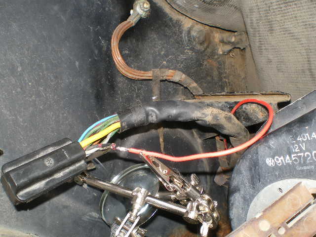
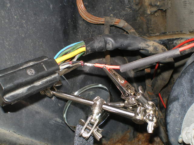
Per the chart below, is pin #13 on the engine comaprtment 14 pin plug a true keyed power source? Being that the chart does not list the fuse it goes to (like it does on pin #8) I am a bit confused. I need to create a harness for my fuel pump and need a keyed power source for the relay. The PO of my car installed a faucet pump and ran it off of the positive side of the coil. I need to check again, but I am pretty confident that the original wires were removed, and for now, I want the new pump (carter 4070) to reside in the stock (rear) location. Thanks Very Much - (IMG:style_emoticons/default/beerchug.gif) Scott S Attached image(s) 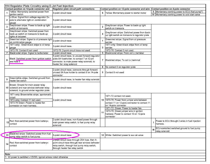
|
   |

 
|
| Spoke |
Sep 7 2011, 10:27 AM
Post
#2
|
|
Jerry Group: Members Posts: 6,978 Joined: 29-October 04 From: Allentown, PA Member No.: 3,031 Region Association: None |
Pin 13 is through fuel pump relay 75 on the relay board. It also comes out on pin 12 of the 12 pin connector towards the engine for the supplementary air valve. Pin 13 of the 14 pin connector and Pin 12 of the 12 pin connector get their power through relay 75 and through the 25A fuse on the relay board.
The 25A fuse gets its power through unswitched pin 14 of the 14 pin connector. Pin 14 goes straight to the battery POS. |
|
|
|
| Tom |
Sep 7 2011, 10:32 AM
Post
#3
|
|
Advanced Member Group: Members Posts: 2,139 Joined: 21-August 05 From: Port Orchard, WA 98367 Member No.: 4,626 Region Association: None |
Yes, pin #13 is for the fuel pump. It's fuse is on the relay board, the rear fuse (25 Amp), although a lower amp fuse is more than adequate, say a 16 amp. It,PIn 13, is only hot when the fuel pump relay is energized.
Tom |
|
|
|
| Scott S |
Sep 7 2011, 10:44 AM
Post
#4
|
|
Small Member Group: Members Posts: 1,697 Joined: 30-April 03 From: Colorado Member No.: 633 |
Shoot - so that wont work? It sounds like the current is running the wrong way?
I am trying to keep things as clean as possible and would really prefer not to have to run a wire to some random keyed powersource at the main fuse box - but If I gotta, I gotta. |
|
|
|
| Valy |
Sep 7 2011, 10:44 AM
Post
#5
|
|
Senior Member Group: Members Posts: 1,675 Joined: 6-April 10 From: Sunnyvale, CA Member No.: 11,573 Region Association: Northern California |
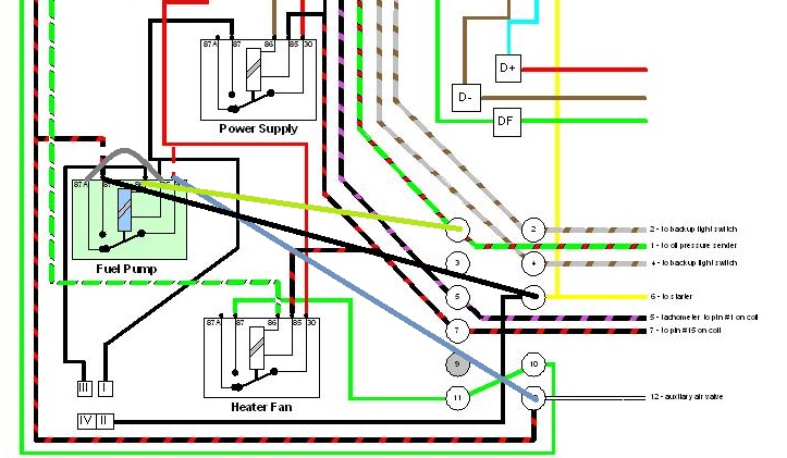
QUOTE(Tom @ Sep 7 2011, 09:32 AM)  Yes, pin #13 is for the fuel pump. It's fuse is on the relay board, the rear fuse (25 Amp), although a lower amp fuse is more than adequate, say a 16 amp. It,PIn 13, is only hot when the fuel pump relay is energized. Tom Always use a relay to cut-off the fuel pump when the engine is not running. This is very cheap insurance! Use simple diagram attached bellow. Switched power is the black (8) in engine compartment or red-white under the dash. I also attached the original relay board wiring with the wire colors. Balck-red (13) is the fuel-pump supply that YOU need to connect to switched power. 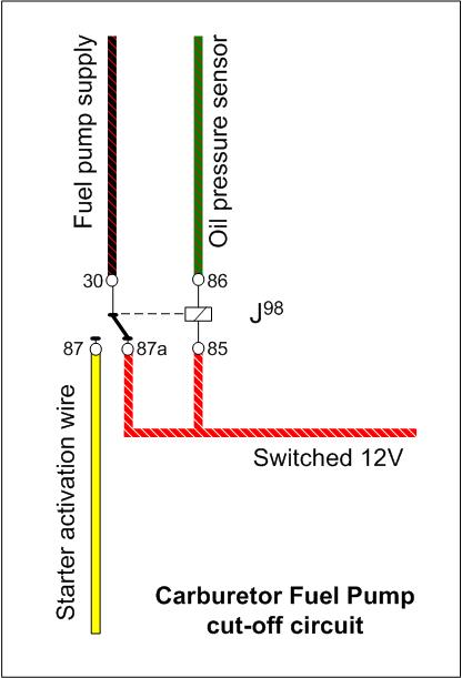 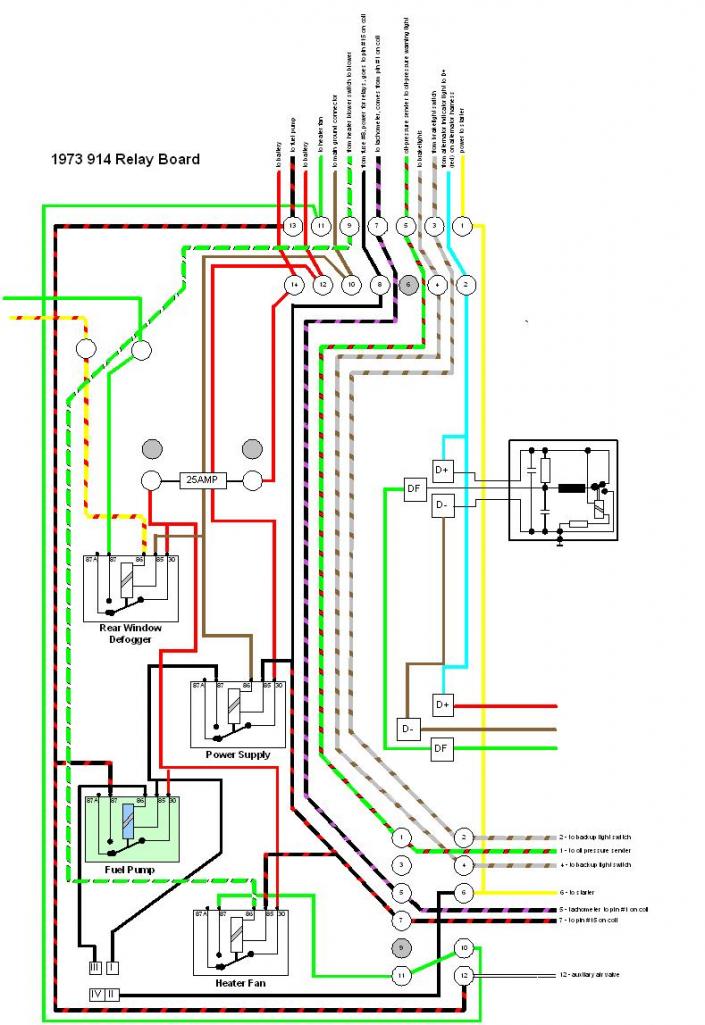 |
|
|
|
| Scott S |
Sep 7 2011, 11:04 AM
Post
#6
|
|
Small Member Group: Members Posts: 1,697 Joined: 30-April 03 From: Colorado Member No.: 633 |
Thanks Valy -
So, I am I looking at this wrong? Is the "power supply" shown on the schmatic the actual relay? If so, I dont understand #30 on the relay. It appears there is a constant 12v hitting both #30 on the relay and #30 on the actual pump - but from two different sources... *edit* "Switched power is the black (8) in engine compartment or red-white under the dash." This may be the simplest way to do things. I have to get into the center tunnel anyway to pirate a wire for my oil pressure guage anyway, so maybe I am over thinking this too much. As per your comment - I totally agree - and want to make sure the pump is wired through a relay vs how it is now. Thanks!!! |
|
|
|
| 76-914 |
Sep 7 2011, 01:46 PM
Post
#7
|
|
Repeat Offender & Resident Subaru Antagonist Group: Members Posts: 13,501 Joined: 23-January 09 From: Temecula, CA Member No.: 9,964 Region Association: Southern California |
is this what you want to do?
  EDIT: Opps, I just noticed your heading. I'm not an electrical guru. In fact i'm not any kind of guru. |
|
|
|
| Mike Bellis |
Sep 7 2011, 02:22 PM
Post
#8
|
|
Resident Electrician Group: Members Posts: 8,345 Joined: 22-June 09 From: Midlothian TX Member No.: 10,496 Region Association: None |
QUOTE(Scott Schroeder @ Sep 7 2011, 09:44 AM) Shoot - so that wont work? It sounds like the current is running the wrong way? I am trying to keep things as clean as possible and would really prefer not to have to run a wire to some random keyed powersource at the main fuse box - but If I gotta, I gotta. If you run a seporate wire, you will never have to locate a loose connection in the wire. Makes troubleshooting much easier. |
|
|
|
| Scott S |
Sep 7 2011, 02:26 PM
Post
#9
|
|
Small Member Group: Members Posts: 1,697 Joined: 30-April 03 From: Colorado Member No.: 633 |
QUOTE(76-914 @ Sep 7 2011, 11:46 AM) is this what you want to do? EDIT: Opps, I just noticed your heading. I'm not an electrical guru. In fact i'm not any kind of guru. Ha! you and me both..... yes, that was my initial plan - just grab pin 13 as a keyed power source. I think that when Perry built my harness he used pin #8 for my MSD, so I did not want to pile to much on to that one circuit. As an FYI - I am not using the relay board. I never pointed that out in all of this - sorry!! |
|
|
|
| r_towle |
Sep 7 2011, 02:37 PM
Post
#10
|
|
Custom Member Group: Members Posts: 24,574 Joined: 9-January 03 From: Taxachusetts Member No.: 124 Region Association: North East States |
Well then, if that is the case, unplug the harness and turn on the key...look for switched power on that plug.
From there, you can use that for the relay trigger... The main power for the relay would be off the battery and then to the fuel pump. Off to radio shack for you...get a good NEW relay. Rich |
|
|
|
| swl |
Sep 7 2011, 02:39 PM
Post
#11
|
|
Senior Member Group: Members Posts: 1,409 Joined: 7-August 05 From: Kingston,On,Canada Member No.: 4,550 Region Association: Canada |
You are dealing with carbs right Scott? If so the fuel pump relay won't work as is. It requires the FI-ECU to do the logic that Valy posted.
I'm thinking though that it might be possible to rewire the relay board to use Valy's cct. Valy does the oil pressure sensor present a ground when pressure is there and high resistance without? That's how the solinoid activates? The normally off position powers the pump from the starter (starting but no oil pressure yet) then when the pressure gets up the relay makes and the power comes from switched power? |
|
|
|
| Valy |
Sep 7 2011, 02:55 PM
Post
#12
|
|
Senior Member Group: Members Posts: 1,675 Joined: 6-April 10 From: Sunnyvale, CA Member No.: 11,573 Region Association: Northern California |
QUOTE(Scott Schroeder @ Sep 7 2011, 10:04 AM) Thanks Valy - So, I am I looking at this wrong? Is the "power supply" shown on the schmatic the actual relay? If so, I dont understand #30 on the relay. It appears there is a constant 12v hitting both #30 on the relay and #30 on the actual pump - but from two different sources... *edit* "Switched power is the black (8) in engine compartment or red-white under the dash." This may be the simplest way to do things. I have to get into the center tunnel anyway to pirate a wire for my oil pressure guage anyway, so maybe I am over thinking this too much. As per your comment - I totally agree - and want to make sure the pump is wired through a relay vs how it is now. Thanks!!! The power supply relay brings switched power to the engine bay so you won't get power drop on the wires through the tunnel. The Fuel Pump relay is wired for the FI. You can't use it that way and not all the relay pins are connected to the board. Just use a regular relay (can be the square ones). The relay wiring I posted will activate the pump only when you crank the engine or there is oil pressure. So if your engine dies, the oil pressure will go off and kill the pump. Really easy to hock it up. |
|
|
|
| Dave_Darling |
Sep 7 2011, 03:04 PM
Post
#13
|
|
914 Idiot Group: Members Posts: 14,986 Joined: 9-January 03 From: Silicon Valley / Kailua-Kona Member No.: 121 Region Association: Northern California |
I think that's backwards. The "idiot light" sender grounds only when pressure drops far enough; that's how the light turns on--the sender supplies the ground for it!
EDIT: Oh, wait--yes, that is how the sender works, but when the light comes on the relay will connect the pump power wire to the starter power wire. So the pump will stop running, which is in fact exactly how you want it to be. Sorry, got confuzzled a bit. --DD |
 |
|
| Scott S |
Sep 7 2011, 03:06 PM
Post
#14
|
|
Small Member Group: Members Posts: 1,697 Joined: 30-April 03 From: Colorado Member No.: 633 |
I thnk I am beginning to understand why the PO just ran a wire to the coil! ha!
(IMG:style_emoticons/default/beerchug.gif) |
|
|
|
| swl |
Sep 7 2011, 03:43 PM
Post
#15
|
|
Senior Member Group: Members Posts: 1,409 Joined: 7-August 05 From: Kingston,On,Canada Member No.: 4,550 Region Association: Canada |
gotcha. Missed the sense of 87 and 87a. So the relay is energized when the oil pressure is low. That makes the connection to the starter wire which provides fuel during start. Engine catches, oil pressure goes up idiot light goes high resistance, relay de-energizes, pin 87 makes and provides the switched power to the pump for normal running.
So... Cut traces to pins 30 and 87. Jumper 85 to 87A as per Valy's diagram. jumper the oil pressure sensor from pin 1 of the 12 pin connector to pin 86 of the relay. Reconnect the fuel pump to pin 30. jumper from Pin 12 of the 12 pin connector to pin 30 jumper starter signal from pin 6 of the 12 pin to pin 87. Might work. Not sure though what the effect would be on the idiot light. Might need a diode in there somewhere. |
|
|
|
| swl |
Sep 7 2011, 03:59 PM
Post
#16
|
|
Senior Member Group: Members Posts: 1,409 Joined: 7-August 05 From: Kingston,On,Canada Member No.: 4,550 Region Association: Canada |
 |
|
|
|
| swl |
Sep 7 2011, 04:02 PM
Post
#17
|
|
Senior Member Group: Members Posts: 1,409 Joined: 7-August 05 From: Kingston,On,Canada Member No.: 4,550 Region Association: Canada |
QUOTE(Scott Schroeder @ Sep 7 2011, 01:06 PM) I thnk I am beginning to understand why the PO just ran a wire to the coil! ha! (IMG:style_emoticons/default/beerchug.gif) he and just about everyone else that has done a carb conversion. It is a fun exercise though for a mad scientist. If it works then you can pick up your fuel pump power from the original wiring harness. |
|
|
|
| Valy |
Sep 8 2011, 11:15 AM
Post
#18
|
|
Senior Member Group: Members Posts: 1,675 Joined: 6-April 10 From: Sunnyvale, CA Member No.: 11,573 Region Association: Northern California |
Don't bother modifying the relay board. It is much too complex.
Just buy a relay + harness and override the board. here is a link to what you need. http://www.ebay.com/itm/BRAND-NEW-4-PIN-AU...9#ht_4834wt_872 You'll find this at any local flaps. |
|
|
|
|
1 User(s) are reading this topic (1 Guests and 0 Anonymous Users)
0 Members:

|
Lo-Fi Version | Time is now: 15th May 2024 - 06:19 PM |
Invision Power Board
v9.1.4 © 2024 IPS, Inc.