|
|
|
Porsche, and the Porsche crest are registered trademarks of Dr. Ing. h.c. F. Porsche AG.
This site is not affiliated with Porsche in any way. Its only purpose is to provide an online forum for car enthusiasts. All other trademarks are property of their respective owners. |
|
|

  |

| Spoke |
 Apr 3 2015, 06:38 AM Apr 3 2015, 06:38 AM
Post
#281
|
|
Jerry  Group: Members Posts: 7,292 Joined: 29-October 04 From: Allentown, PA Member No.: 3,031 Region Association: None |
QUOTE(Vacca Rabite @ Apr 2 2015, 07:45 PM)  So right now this is my plan for the test board. (IMG:http://www.914world.com/bbs2/uploads_offsite/farm9.staticflickr.com-1435-1428018341.1.jpg) Please look and see if I have something glaring. Do I need to add a circuit? I think I only need 3 circuits at this time. 1) Power 2) Coms 3) Bootloader Ground I have a 15 volt, 1.4 amp power AC to DC power converter on hand. This will allow me to plug the test box into a wall and not have to fiddle with batteries. The numbers inside circles are the pins to the Ampseal jack. Boot loader will be on a switch instead of plugging and unplugging a wire, with an LED to show when it is grounding. Zach If pin 1 is the power pin, the LED should not be in series with it unless the manufacturer says so. If you want an LED to let you know when power is on, the LED should be connected between the switched power and ground through a resistor of about 5-10k ohms. A couple of things from previous posts: You 'may' be able to see some resistance from power to ground with the power off. If it was a dead short, it would show up as zero ohms. This is not a conclusive test. About the power supply noise, chances are the automotive voltage rails are about as noisy as can be. The electronics in the MS run off a low voltage like 5V or 3.3V or lower and likely have significant filtering from the input power to the conditioned digital power. Still a good idea to have as quiet a power supply as possible. If you're going to have a fuse in the path, why not use a car battery? The load on the battery has to be minor and should give hours of running just the MS. |
   |

 
|
| VaccaRabite |
Apr 3 2015, 06:43 AM
Post
#282
|
|
En Garde! Group: Admin Posts: 13,826 Joined: 15-December 03 From: Dallastown, PA Member No.: 1,435 Region Association: MidAtlantic Region |
I don't have a spare car battery. My 914 and its battery are at Tony's shop.
|
 |
|
| Spoke |
Apr 3 2015, 07:12 AM
Post
#283
|
|
Jerry Group: Members Posts: 7,292 Joined: 29-October 04 From: Allentown, PA Member No.: 3,031 Region Association: None |
Your power supply should be ok.
What exactly happened that the MS stopped working? I read through your thread but couldn't tell when the ECU stopped working. I'll offer to take a look at it and see what's wrong. We do electronic solution development at work and have a lot of experience with small systems like MS. Here's one we just finished. It's a camera on a needle for probing knees and shoulders. Pretty cool. We did the camera board (me) and the base processor and software. It runs Android. (IMG:style_emoticons/default/barf.gif) Trice Medical Mi-Eye |
|
|
|
| crash914 |
Apr 3 2015, 08:06 AM
Post
#284
|
|
its a mystery to me Group: Members Posts: 1,830 Joined: 17-March 03 From: Marriottsville, MD Member No.: 434 Region Association: MidAtlantic Region |
|
|
|
|
| crash914 |
Apr 3 2015, 08:06 AM
Post
#285
|
|
its a mystery to me Group: Members Posts: 1,830 Joined: 17-March 03 From: Marriottsville, MD Member No.: 434 Region Association: MidAtlantic Region |
it could be just the rs232 chip that is no good....
|
|
|
|
| McMark |
Apr 3 2015, 08:38 AM
Post
#286
|
|
914 Freak! Group: Retired Admin Posts: 20,180 Joined: 13-March 03 From: Grand Rapids, MI Member No.: 419 Region Association: None |
Careful of changes by version. That schematic is v2.2, the ECU is v3.
|
|
|
|
| crash914 |
Apr 3 2015, 08:40 AM
Post
#287
|
|
its a mystery to me Group: Members Posts: 1,830 Joined: 17-March 03 From: Marriottsville, MD Member No.: 434 Region Association: MidAtlantic Region |
yea, i thought about that.....ver 3.0 is also available...
|
|
|
|
| VaccaRabite |
Apr 3 2015, 09:12 AM
Post
#288
|
|
En Garde! Group: Admin Posts: 13,826 Joined: 15-December 03 From: Dallastown, PA Member No.: 1,435 Region Association: MidAtlantic Region |
QUOTE(Spoke @ Apr 3 2015, 08:12 AM) Your power supply should be ok. What exactly happened that the MS stopped working? I read through your thread but couldn't tell when the ECU stopped working. I'll offer to take a look at it and see what's wrong. We do electronic solution development at work and have a lot of experience with small systems like MS. Here's one we just finished. It's a camera on a needle for probing knees and shoulders. Pretty cool. We did the camera board (me) and the base processor and software. It runs Android. (IMG:style_emoticons/default/barf.gif) Trice Medical Mi-Eye I don't know. I was not there. All I know is what was stated. They had it connected, ad then it stopped communicating. Could I get you to draw out the circuit (so a dummy layman like me could build it) so that I can have the LEDs light up when there is power to their circuit? Zach |
|
|
|
| Spoke |
Apr 3 2015, 10:29 AM
Post
#289
|
|
Jerry Group: Members Posts: 7,292 Joined: 29-October 04 From: Allentown, PA Member No.: 3,031 Region Association: None |
QUOTE(crash914 @ Apr 3 2015, 10:06 AM) Thanks but the link just takes me to a logo.gif file. I looked on the MS website but still didn't find the schematic. Got another link to the schematic? |
|
|
|
| Spoke |
Apr 3 2015, 10:43 AM
Post
#290
|
|
Jerry Group: Members Posts: 7,292 Joined: 29-October 04 From: Allentown, PA Member No.: 3,031 Region Association: None |
QUOTE(Vacca Rabite @ Apr 3 2015, 11:12 AM) Could I get you to draw out the circuit (so a dummy layman like me could build it) so that I can have the LEDs light up when there is power to their circuit? Zach Here's the main part of the circuit. The LED with the bootloader is not in the right place but I don't have a schematic to add this to it. When you connect the power from the wall wart, do not connect the MS to it yet. Connect the fuse, switch, LED and resistor and try the power. If the LED doesn't light when you close the switch, the voltage is backwards. If the LED lights when the switch is closed, then the power is correct. Then turn the switch off and connect the MS. When you're done with this and it doesn't work, you can give it to me and perhaps I can get it running and give it to you at Hershey. BTW, I pass through Harrisburg 2 times a week if you want to drop it off. Attached image(s) 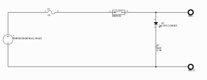
|
|
|
|
| McMark |
Apr 3 2015, 12:07 PM
Post
#291
|
|
914 Freak! Group: Retired Admin Posts: 20,180 Joined: 13-March 03 From: Grand Rapids, MI Member No.: 419 Region Association: None |
QUOTE(Vacca Rabite @ Apr 3 2015, 05:43 AM) I don't have a spare car battery. My 914 and its battery are at Tony's shop. Motorcycle batteries are pretty cheap and make great tester batteries for all sorts of automotive projects. (IMG:style_emoticons/default/wink.gif) |
|
|
|
| crash914 |
Apr 3 2015, 05:07 PM
Post
#292
|
|
its a mystery to me Group: Members Posts: 1,830 Joined: 17-March 03 From: Marriottsville, MD Member No.: 434 Region Association: MidAtlantic Region |
Let's try this one.
Never mind......can't cut and paste |
|
|
|
| VaccaRabite |
Apr 3 2015, 05:55 PM
Post
#293
|
|
En Garde! Group: Admin Posts: 13,826 Joined: 15-December 03 From: Dallastown, PA Member No.: 1,435 Region Association: MidAtlantic Region |
Herb, i may come to pick your brain when I get the tester built. Youve done this before and that may come inhandy trying to get the ECU back on line.
Zach |
|
|
|
| crash914 |
Apr 3 2015, 06:14 PM
Post
#294
|
|
its a mystery to me Group: Members Posts: 1,830 Joined: 17-March 03 From: Marriottsville, MD Member No.: 434 Region Association: MidAtlantic Region |
No problem...Jim stim and unit on my bench. I think I have everything to fab a cable if needed...
|
|
|
|
| VaccaRabite |
Apr 9 2015, 07:16 PM
Post
#295
|
|
En Garde! Group: Admin Posts: 13,826 Joined: 15-December 03 From: Dallastown, PA Member No.: 1,435 Region Association: MidAtlantic Region |
Well, I built the breadboard for the power circuit, and found an issue.
My 15 volt power supply (which would have been perfect for this) is actually a 20 volt power supply. Glad I checked it with a multimeter before connecting the MS unit. Microsquirt can take a 9V to 17v supply. Looks like its time to go get a lawn tractor battery. At least I'll have a hot spare when the battery on my tractor dies. Zach |
|
|
|
| VaccaRabite |
Apr 11 2015, 09:18 PM
Post
#296
|
|
En Garde! Group: Admin Posts: 13,826 Joined: 15-December 03 From: Dallastown, PA Member No.: 1,435 Region Association: MidAtlantic Region |
Tester for power built.
(IMG:http://www.914world.com/bbs2/uploads_offsite/farm8.staticflickr.com-1435-1428808725.1.jpg) tested with the meter: 12.68 volts. In business. Attach the leads and put 12 volts on the Microsquirt controller. No problem. Turn that off, and go to hook up laptop. Zach |
|
|
|
| VaccaRabite |
Apr 11 2015, 09:34 PM
Post
#297
|
|
En Garde! Group: Admin Posts: 13,826 Joined: 15-December 03 From: Dallastown, PA Member No.: 1,435 Region Association: MidAtlantic Region |
My laptop has sucessfully communicated with Microsquirt!!!!!!!!
WOOOO! (IMG:http://www.914world.com/bbs2/uploads_offsite/farm9.staticflickr.com-1435-1428809738.1.jpg) Now I just need to figure out why it won't on my car... My laptop detected the microsquirt ecu within second of plugging it in, so I know the ECU is good. I also know my laptop is good. Harness? Ground loop? zach |
|
|
|
| VaccaRabite |
Apr 11 2015, 09:54 PM
Post
#298
|
|
En Garde! Group: Admin Posts: 13,826 Joined: 15-December 03 From: Dallastown, PA Member No.: 1,435 Region Association: MidAtlantic Region |
So here is my theory.
This test circuit only has power and ground and communications. Nothing else is hooked up. I recall in the startup file I was reading again last night it said to unhook all the sensor leads and make sure they are not grounding anywhere. I bet this is the issue. The leads are unplugged but were just laying in the engine bay. I bet they are grounding and creating some sort of connection problem. The other possibility is a fault in the harness. Maybe a bad crimp somewhere. Though I tested continuity on the harness and I got a solid tone each time, so this is not a strong theory. Wont know till I can get back to the 914, which may have to wait till after Hershey - depending on Tony's schedule. Zach |
|
|
|
| VaccaRabite |
Apr 14 2015, 10:21 AM
Post
#299
|
|
En Garde! Group: Admin Posts: 13,826 Joined: 15-December 03 From: Dallastown, PA Member No.: 1,435 Region Association: MidAtlantic Region |
Brain goes back in the catr on Thursday for further testing. I had taken thursday off for Hershey anyhow, so this will be good timing.
Still, excited that I was able to get my laptop to talk to it, eleminating the ECU and my laptop as the issue. Zach |
|
|
|
| VaccaRabite |
Apr 16 2015, 10:47 AM
Post
#300
|
|
En Garde! Group: Admin Posts: 13,826 Joined: 15-December 03 From: Dallastown, PA Member No.: 1,435 Region Association: MidAtlantic Region |
No dice. Once in the car the ECU failed to connect again. I pulled everything that could be causing a ground loop out, still no love.
Finally pulled the wire harness to bench test at home. I may do this tonight at the Knights Inn, since the whole mess is in my car already. Stuff I tested: there is power for sure. 12 volts. Grounds are clean. Grounds go from the engine block to 1 place on the engine harness - so we should be getting a clean ground to the ECU. The harness is the only thing I can think of at this point that would be causing a problem. Hopefully I will be able to figure that out tonight or tomorrow. Zach |
|
|
|
|
1 User(s) are reading this topic (1 Guests and 0 Anonymous Users)
0 Members:

|
Lo-Fi Version | Time is now: 19th December 2025 - 04:06 PM |
Invision Power Board
v9.1.4 © 2025 IPS, Inc.