|
|
|
Porsche, and the Porsche crest are registered trademarks of Dr. Ing. h.c. F. Porsche AG.
This site is not affiliated with Porsche in any way. Its only purpose is to provide an online forum for car enthusiasts. All other trademarks are property of their respective owners. |
|
|


| dlee6204 |
 Aug 22 2012, 08:05 PM Aug 22 2012, 08:05 PM
Post
#21
|
|
Howdy  Group: Members Posts: 2,162 Joined: 30-April 06 From: Burnsville, NC Member No.: 5,956 |
I thought I would document my A/C adventure in the hopes that it would be a good reference for anyone else considering A/C. I’ll first touch base on the stock system and on custom options and then start building my own system to start testing on. I’ve working on a few systems before but I'm sure there is someone that knows more than me so don't be shy sharing or adding anything. (IMG:style_emoticons/default/smile.gif)
To begin things off here is one of the better overviews of an A/C system. Follow the link and you can see a breakdown of the whole system. 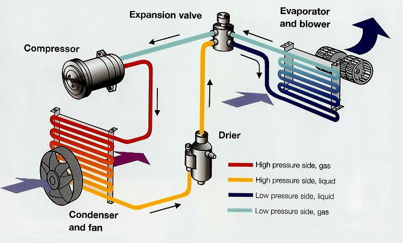 http://www.movacs.com/How%20it%20works/index.html Anytime I refer to the stock system I will be referring to the dealer installed VPC system mostly because the only A/C cars I had came with this system and I have plenty of parts around. I also borrowed some photos off this site so if I used any of yours... Thanks. (IMG:style_emoticons/default/smile.gif) Compressor: The compressor that came on dealer installed A/C systems was a York Piston style compressor that had a capacity of 6 cubic inches/Rev. From what I could find it used about 7-10 horsepower from the engine. You can still use this compressor however there are better, more efficient options out there. When choosing a new compressor it is a good idea to find one with a similar capacity. In this case going bigger does not mean better. An A/C system works as a whole unit and if you dramatically change one aspect of it, you will likely see negatives effects elsewhere. Choosing a compressor that’s too big will overwork the system, yielding no little to no benefit, and create a not-as-efficient system. During my search I looked mostly at Sanden style compressors so that's what I'll be referring to in my build. Using a modern compressor like the Sanden will only use about 3-4 hp from the engine. I have heard quite a few people use the Sanden 508 compressor with good results. It has an approximate displacement of 8 cubic inches/rev, which IMO is slightly more than I'd like to make a jump to. I'm not saying it wouldn't work, it obviously works, however I think I will get slightly better results and pressures using the Sanden 507 (approx. 7 cubic inches/rev). The SD507 is also slightly smaller in size than the 508. Here is a picture of the York Compressor 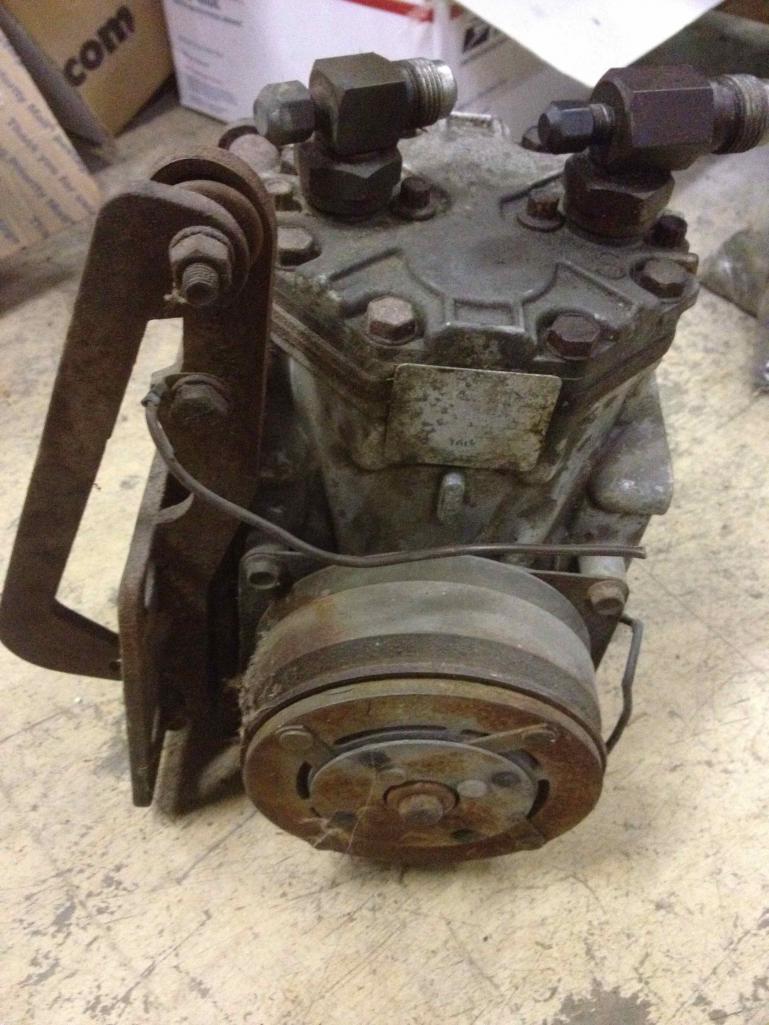 A side by side with the SD507 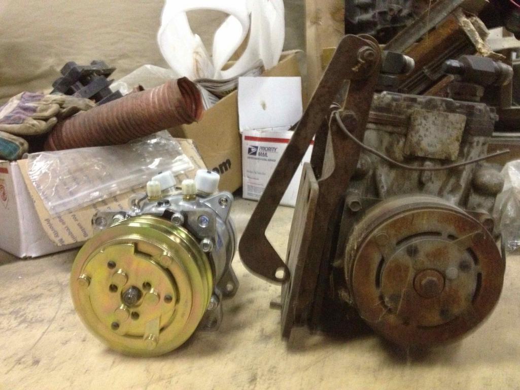 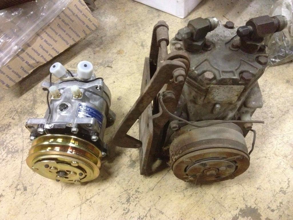 And here is a SD508 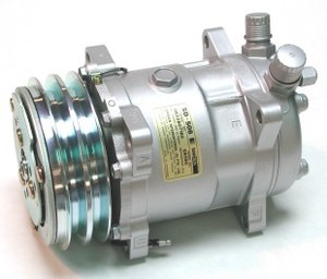 |
   |

 
|
Posts in this topic
dlee6204 Doug's A/C System Aug 22 2012, 08:05 PM dlee6204 Compressor Mounting:
This is probably the bigge... Aug 22 2012, 08:05 PM dlee6204 Condenser:
IMO this is where the biggest improve... Aug 22 2012, 08:05 PM dlee6204 Hoses:
Chances are that anyone doing an A/C syste... Aug 22 2012, 08:05 PM dlee6204 [Future Post] Aug 22 2012, 08:05 PM dlee6204 Reference Pictures:
Aug 22 2012, 08:05 PM billh1963 I just removed my York compressor. I could "p... Aug 22 2012, 08:26 PM dlee6204
I just removed my York compressor. I could ... Aug 22 2012, 08:57 PM dlee6204 So for my build I will be starting from scratch. ... Aug 22 2012, 09:02 PM dlee6204 The first thing I did was install the front conden... Aug 22 2012, 09:08 PM wingnut86 I checked into aftermarket systems for ACs last ye... Aug 22 2012, 09:49 PM zambezi Here are some of my condensor mountings. I am run... Aug 22 2012, 11:31 PM
dlee6204 Compressor Mounting:
This is probably the bigge... Aug 22 2012, 08:05 PM dlee6204 Condenser:
IMO this is where the biggest improve... Aug 22 2012, 08:05 PM dlee6204 Hoses:
Chances are that anyone doing an A/C syste... Aug 22 2012, 08:05 PM dlee6204 [Future Post] Aug 22 2012, 08:05 PM dlee6204 Reference Pictures:
Aug 22 2012, 08:05 PM billh1963 I just removed my York compressor. I could "p... Aug 22 2012, 08:26 PM dlee6204
I just removed my York compressor. I could ... Aug 22 2012, 08:57 PM dlee6204 So for my build I will be starting from scratch. ... Aug 22 2012, 09:02 PM dlee6204 The first thing I did was install the front conden... Aug 22 2012, 09:08 PM wingnut86 I checked into aftermarket systems for ACs last ye... Aug 22 2012, 09:49 PM zambezi Here are some of my condensor mountings. I am run... Aug 22 2012, 11:31 PM
 mtburman It's important to watch spacing on the condens... Aug 23 2012, 11:28 AM JRust Man I appreciate this. I will be setting up a/c in... Aug 22 2012, 11:58 PM Philip W. :Qarl: excellent thread to document for those of ... Aug 23 2012, 06:46 AM dlee6204
if you can share your parts lists and sources fo... Aug 23 2012, 07:39 AM dlee6204
I'd be interested in hearing how much cleara... Aug 23 2012, 07:56 AM 76-914 :popcorn: Aug 23 2012, 08:16 AM TJB/914 :popcorn:
Drive pulley.
T Aug 23 2012, 08:49 AM andys In a couple of days I can hopefully provide some p... Aug 23 2012, 09:51 AM dlee6204
In a couple of days I can hopefully provide some ... Aug 23 2012, 02:57 PM andys
Interesting. Please keep us updated. Do you hav... Aug 23 2012, 04:48 PM dlee6204 I updated post #9 with a more detailed list of par... Aug 23 2012, 04:53 PM dlee6204 After getting the condenser in I began routing my ... Aug 23 2012, 05:06 PM dlee6204 And while we are on the subject of hoses.... I ma... Aug 23 2012, 05:13 PM dlee6204 The Evaporator install was pretty straight forward... Aug 23 2012, 05:18 PM dlee6204 Onto the compressor... I decided to go with a to... Aug 23 2012, 06:33 PM dlee6204 Some more pictures on the test engine.
I ended... Aug 23 2012, 06:38 PM dlee6204 More
Finished
Aug 23 2012, 06:43 PM Jeff Bowlsby Do you have to remove the compressor to time the e... Aug 23 2012, 06:57 PM FourBlades Great thread, thanks for posting this. :Qarl:
... Aug 23 2012, 06:59 PM dlee6204
Do you have to remove the compressor to time the ... Aug 23 2012, 07:08 PM cgnj
Do you have to remove the compressor to time the... Aug 23 2012, 07:14 PM hot_shoe914 Best damn thread EVER in the garage!
:first:... Aug 23 2012, 07:20 PM dlee6204
Good idea! Aug 23 2012, 07:27 PM dlee6204 The best thing about this whole setup is that IT W... Aug 23 2012, 07:33 PM gothspeed fantastic thread :trophy:
when my car gets done... Aug 23 2012, 09:09 PM metalmorphosis Awesome Doug can't wait to go for a ride somet... Aug 23 2012, 09:19 PM zambezi
My hoses were originally run that way.... Aug 23 2012, 09:52 PM zambezi Here are the other pics I took tonight of the comp... Aug 23 2012, 10:02 PM zambezi These pictures have been posted on this forum befo... Aug 23 2012, 10:09 PM dlee6204 Thanks for the pictures. I think my setup is a lit... Aug 24 2012, 08:17 AM Cohibra45 Definitely needs to be in the tech articles when c... Aug 24 2012, 08:46 AM andys I know I'm delinquent with posting photos of m... Aug 24 2012, 09:59 AM dlee6204 I thought I would share some additional informatio... Aug 26 2012, 08:12 PM 76-914 Any new developments? Nov 7 2012, 08:58 PM dlee6204 I ran into a few small issues dealing with the smo... Nov 7 2012, 09:20 PM dlee6204 I also have a few more changes to make to the syst... Nov 7 2012, 09:27 PM dlee6204 Oh and here is a thread by andys on a different ap... Nov 7 2012, 09:27 PM 76-914 Just wondered. I will be doing a Suby conversion s... Nov 8 2012, 08:25 AM dlee6204 I made some progress on my A/C pulley. As I state... Nov 25 2012, 04:12 PM zambezi looks like a great design. very similar to my cas... Nov 25 2012, 05:09 PM stateofidleness Cool Thread! Makes me appreciate my "fact... Nov 25 2012, 07:05 PM dlee6204
Do you have any pictures of it? How is it drive... Nov 25 2012, 07:40 PM stateofidleness I'll see if I can snap some pics of it. It... Nov 25 2012, 07:46 PM dlee6204
looks like a great design. very similar to my ca... Nov 25 2012, 08:06 PM ScoopLV Ugh... this is something I'd totally love to d... Nov 26 2012, 02:12 AM gothspeed When I eventually get to the A/C ............ I wa... Nov 27 2012, 06:43 PM dlee6204 I just finished making a new mount. :) I'm... Dec 15 2012, 08:55 AM dlee6204 RE: Doug's A/C System Dec 15 2012, 08:56 AM 76-914 Looking good in the hood my friend. :popcorn: Dec 15 2012, 09:16 AM wingnut86 Agreed :D
So, what's the weakest link in the... Dec 15 2012, 10:56 AM stateofidleness Finally got to the car last weekend and snapped so... Dec 15 2012, 01:39 PM ClayPerrine
Finally got to the car last weekend and snapped s... Dec 16 2012, 12:17 PM zambezi I am curios to know what pulley you have to drive ... Dec 15 2012, 09:35 PM dlee6204
Agreed :D
So, what's the weakest link in th... Dec 15 2012, 09:40 PM dlee6204 stateofidleness, Thanks for the pics.
:agre... Dec 15 2012, 09:43 PM wingnut86 I found the link to the company that built Jake Ra... Dec 15 2012, 11:17 PM rfuerst911sc I plan to make a AC system for my GT clone sometim... Dec 16 2012, 04:32 AM stateofidleness K guys, I wanted to dig in a little more on this b... Dec 16 2012, 07:39 PM stateofidleness Couple more... left them a little bigger because i... Dec 16 2012, 07:49 PM stateofidleness Uno Mas. Markings on the visible side of the compr... Dec 16 2012, 07:51 PM stateofidleness Couple more reference pics as I finished getting t... Dec 28 2012, 03:35 PM dlee6204 stateofidleness, Did you ever figure out how your... Jan 24 2013, 07:48 PM dlee6204 Not a big update but I did finish the pulley adapt... Jan 24 2013, 07:51 PM dlee6204 Version 2.0 is now up an running. I put a new mot... May 29 2013, 08:00 AM dlee6204 Oh and for those wondering, to set the timing I us... May 29 2013, 09:28 AM dlee6204 Now for some boring stuff...
I thought I would ... Jun 1 2013, 02:35 PM FourBlades Nice work!
I am sure a lot of people would li... Jun 1 2013, 06:02 PM dlee6204 Just an update. I made a batch of extra adapters ... Sep 9 2013, 07:41 PM timothy_nd28 I'll take an adapter!
Nice work :beer2: Sep 9 2013, 07:43 PM dlee6204 BUMP :D
http://www.914world.com/bbs2/index.ph... Oct 21 2013, 10:45 AM rsrguy3 Aside from selling kits what was the conclusion? D... Mar 1 2014, 05:42 AM dlee6204 This system will keep you cool even on a hot day. ... Mar 1 2014, 06:59 AM 3d914
This system will keep you cool even on a hot day.... Mar 7 2014, 11:54 AM HalfMoon Terrific and very informative thread. I'm very... Mar 3 2014, 06:01 PM HalfMoon Here's a few images Steve from Renegade just s... Mar 3 2014, 06:59 PM terryth Good thread. I am embarking on my own AC install p... Mar 25 2017, 05:23 PM DRPHIL914 just check into this since you have the link on yo... Nov 6 2018, 08:11 AM Literati914 Interested in thoughts on which, (if either) might... Nov 9 2018, 06:24 PM Chris914n6
Interested in thoughts on which, (if either) migh... Nov 9 2018, 11:53 PM friethmiller Condenser Install I think I mistakenly placed my ... Apr 29 2021, 02:48 PM DRPHIL914
Condenser Install I think I mistakenly placed my... Apr 30 2021, 12:06 PM DRPHIL914
Condenser Install I think I mistakenly placed my... Apr 30 2021, 12:07 PM Chris914n6
Condenser Install I think I mistakenly placed my... Apr 30 2021, 03:35 PM friethmiller Thanks! Good comments here. I like the idea ... May 3 2021, 08:43 AM friethmiller Starting the A/C Compressor Install. Hired a youn... Jul 27 2021, 10:04 AM 914sgofast2
Starting the A/C Compressor Install. Hired a you... Jul 27 2021, 11:46 AM Shivers Very cool build Jul 27 2021, 11:59 AM dlee6204
How will you set or check the engine timing with... Jul 27 2021, 02:02 PM
mtburman It's important to watch spacing on the condens... Aug 23 2012, 11:28 AM JRust Man I appreciate this. I will be setting up a/c in... Aug 22 2012, 11:58 PM Philip W. :Qarl: excellent thread to document for those of ... Aug 23 2012, 06:46 AM dlee6204
if you can share your parts lists and sources fo... Aug 23 2012, 07:39 AM dlee6204
I'd be interested in hearing how much cleara... Aug 23 2012, 07:56 AM 76-914 :popcorn: Aug 23 2012, 08:16 AM TJB/914 :popcorn:
Drive pulley.
T Aug 23 2012, 08:49 AM andys In a couple of days I can hopefully provide some p... Aug 23 2012, 09:51 AM dlee6204
In a couple of days I can hopefully provide some ... Aug 23 2012, 02:57 PM andys
Interesting. Please keep us updated. Do you hav... Aug 23 2012, 04:48 PM dlee6204 I updated post #9 with a more detailed list of par... Aug 23 2012, 04:53 PM dlee6204 After getting the condenser in I began routing my ... Aug 23 2012, 05:06 PM dlee6204 And while we are on the subject of hoses.... I ma... Aug 23 2012, 05:13 PM dlee6204 The Evaporator install was pretty straight forward... Aug 23 2012, 05:18 PM dlee6204 Onto the compressor... I decided to go with a to... Aug 23 2012, 06:33 PM dlee6204 Some more pictures on the test engine.
I ended... Aug 23 2012, 06:38 PM dlee6204 More
Finished
Aug 23 2012, 06:43 PM Jeff Bowlsby Do you have to remove the compressor to time the e... Aug 23 2012, 06:57 PM FourBlades Great thread, thanks for posting this. :Qarl:
... Aug 23 2012, 06:59 PM dlee6204
Do you have to remove the compressor to time the ... Aug 23 2012, 07:08 PM cgnj
Do you have to remove the compressor to time the... Aug 23 2012, 07:14 PM hot_shoe914 Best damn thread EVER in the garage!
:first:... Aug 23 2012, 07:20 PM dlee6204
Good idea! Aug 23 2012, 07:27 PM dlee6204 The best thing about this whole setup is that IT W... Aug 23 2012, 07:33 PM gothspeed fantastic thread :trophy:
when my car gets done... Aug 23 2012, 09:09 PM metalmorphosis Awesome Doug can't wait to go for a ride somet... Aug 23 2012, 09:19 PM zambezi
My hoses were originally run that way.... Aug 23 2012, 09:52 PM zambezi Here are the other pics I took tonight of the comp... Aug 23 2012, 10:02 PM zambezi These pictures have been posted on this forum befo... Aug 23 2012, 10:09 PM dlee6204 Thanks for the pictures. I think my setup is a lit... Aug 24 2012, 08:17 AM Cohibra45 Definitely needs to be in the tech articles when c... Aug 24 2012, 08:46 AM andys I know I'm delinquent with posting photos of m... Aug 24 2012, 09:59 AM dlee6204 I thought I would share some additional informatio... Aug 26 2012, 08:12 PM 76-914 Any new developments? Nov 7 2012, 08:58 PM dlee6204 I ran into a few small issues dealing with the smo... Nov 7 2012, 09:20 PM dlee6204 I also have a few more changes to make to the syst... Nov 7 2012, 09:27 PM dlee6204 Oh and here is a thread by andys on a different ap... Nov 7 2012, 09:27 PM 76-914 Just wondered. I will be doing a Suby conversion s... Nov 8 2012, 08:25 AM dlee6204 I made some progress on my A/C pulley. As I state... Nov 25 2012, 04:12 PM zambezi looks like a great design. very similar to my cas... Nov 25 2012, 05:09 PM stateofidleness Cool Thread! Makes me appreciate my "fact... Nov 25 2012, 07:05 PM dlee6204
Do you have any pictures of it? How is it drive... Nov 25 2012, 07:40 PM stateofidleness I'll see if I can snap some pics of it. It... Nov 25 2012, 07:46 PM dlee6204
looks like a great design. very similar to my ca... Nov 25 2012, 08:06 PM ScoopLV Ugh... this is something I'd totally love to d... Nov 26 2012, 02:12 AM gothspeed When I eventually get to the A/C ............ I wa... Nov 27 2012, 06:43 PM dlee6204 I just finished making a new mount. :) I'm... Dec 15 2012, 08:55 AM dlee6204 RE: Doug's A/C System Dec 15 2012, 08:56 AM 76-914 Looking good in the hood my friend. :popcorn: Dec 15 2012, 09:16 AM wingnut86 Agreed :D
So, what's the weakest link in the... Dec 15 2012, 10:56 AM stateofidleness Finally got to the car last weekend and snapped so... Dec 15 2012, 01:39 PM ClayPerrine
Finally got to the car last weekend and snapped s... Dec 16 2012, 12:17 PM zambezi I am curios to know what pulley you have to drive ... Dec 15 2012, 09:35 PM dlee6204
Agreed :D
So, what's the weakest link in th... Dec 15 2012, 09:40 PM dlee6204 stateofidleness, Thanks for the pics.
:agre... Dec 15 2012, 09:43 PM wingnut86 I found the link to the company that built Jake Ra... Dec 15 2012, 11:17 PM rfuerst911sc I plan to make a AC system for my GT clone sometim... Dec 16 2012, 04:32 AM stateofidleness K guys, I wanted to dig in a little more on this b... Dec 16 2012, 07:39 PM stateofidleness Couple more... left them a little bigger because i... Dec 16 2012, 07:49 PM stateofidleness Uno Mas. Markings on the visible side of the compr... Dec 16 2012, 07:51 PM stateofidleness Couple more reference pics as I finished getting t... Dec 28 2012, 03:35 PM dlee6204 stateofidleness, Did you ever figure out how your... Jan 24 2013, 07:48 PM dlee6204 Not a big update but I did finish the pulley adapt... Jan 24 2013, 07:51 PM dlee6204 Version 2.0 is now up an running. I put a new mot... May 29 2013, 08:00 AM dlee6204 Oh and for those wondering, to set the timing I us... May 29 2013, 09:28 AM dlee6204 Now for some boring stuff...
I thought I would ... Jun 1 2013, 02:35 PM FourBlades Nice work!
I am sure a lot of people would li... Jun 1 2013, 06:02 PM dlee6204 Just an update. I made a batch of extra adapters ... Sep 9 2013, 07:41 PM timothy_nd28 I'll take an adapter!
Nice work :beer2: Sep 9 2013, 07:43 PM dlee6204 BUMP :D
http://www.914world.com/bbs2/index.ph... Oct 21 2013, 10:45 AM rsrguy3 Aside from selling kits what was the conclusion? D... Mar 1 2014, 05:42 AM dlee6204 This system will keep you cool even on a hot day. ... Mar 1 2014, 06:59 AM 3d914
This system will keep you cool even on a hot day.... Mar 7 2014, 11:54 AM HalfMoon Terrific and very informative thread. I'm very... Mar 3 2014, 06:01 PM HalfMoon Here's a few images Steve from Renegade just s... Mar 3 2014, 06:59 PM terryth Good thread. I am embarking on my own AC install p... Mar 25 2017, 05:23 PM DRPHIL914 just check into this since you have the link on yo... Nov 6 2018, 08:11 AM Literati914 Interested in thoughts on which, (if either) might... Nov 9 2018, 06:24 PM Chris914n6
Interested in thoughts on which, (if either) migh... Nov 9 2018, 11:53 PM friethmiller Condenser Install I think I mistakenly placed my ... Apr 29 2021, 02:48 PM DRPHIL914
Condenser Install I think I mistakenly placed my... Apr 30 2021, 12:06 PM DRPHIL914
Condenser Install I think I mistakenly placed my... Apr 30 2021, 12:07 PM Chris914n6
Condenser Install I think I mistakenly placed my... Apr 30 2021, 03:35 PM friethmiller Thanks! Good comments here. I like the idea ... May 3 2021, 08:43 AM friethmiller Starting the A/C Compressor Install. Hired a youn... Jul 27 2021, 10:04 AM 914sgofast2
Starting the A/C Compressor Install. Hired a you... Jul 27 2021, 11:46 AM Shivers Very cool build Jul 27 2021, 11:59 AM dlee6204
How will you set or check the engine timing with... Jul 27 2021, 02:02 PM  |
2 User(s) are reading this topic (2 Guests and 0 Anonymous Users)
0 Members:

|
Lo-Fi Version | Time is now: 17th May 2026 - 05:32 PM |
Invision Power Board
v9.1.4 © 2026 IPS, Inc.