|
|
|
Porsche, and the Porsche crest are registered trademarks of Dr. Ing. h.c. F. Porsche AG.
This site is not affiliated with Porsche in any way. Its only purpose is to provide an online forum for car enthusiasts. All other trademarks are property of their respective owners. |
|
|

  |

| wrightee |
 Sep 2 2012, 12:15 PM Sep 2 2012, 12:15 PM
Post
#1
|
|
Member  Group: Members Posts: 83 Joined: 18-November 09 From: Montclair, VA Member No.: 11,053 Region Association: MidAtlantic Region |
I have a '75 1.8L L-Jet that has sat for a while. Its my parts car, but I'm trying to get it running now.
When I got it, the fellow told me the double relay was bad, so I replaced that. Fuel lines were also totally gummed at the tank, so those have been changed, tank cleaned and fuel filter replaced. I also had the fuel injectors tested and cleanded. I had also found a shredded "stray" wire, which turned out to be the engine temp sensor (under the engine sheet metal), which was replaced. The car will "fire" when I spray starting fluid in the intake. I don't have a pressure guage, but the pressure is sufficient to blow an improperly clamped fuel line off the fuel rail (I had an injector out, and some fuel must've sprayed into the hole, causing a "sputtering" near-start). I pulled the injectors to see if they were spraying, and they are not. When I manipulate the AFM flap, I can hear both the fuel pump as well as a "hissing" sound from the pressure regulator (but can not see any leaks). Troubleshooting these type issues is not my strength (IMG:style_emoticons/default/confused24.gif) so any help/advice on where I need to look next would be greatly appreciated. |
   |

 
|
| dlee6204 |
Sep 2 2012, 12:26 PM
Post
#2
|
|
Howdy Group: Members Posts: 2,162 Joined: 30-April 06 From: Burnsville, NC Member No.: 5,956 |
Double check the connections on the resistor pack. It should be a silver piece located next to the double relay. The connections often become brittle and break off.
|
|
|
|
| jsayre914 |
Sep 2 2012, 12:36 PM
Post
#3
|
|
Speed Up !!! Group: Members Posts: 3,210 Joined: 10-February 08 From: Timonium MD 21093 Member No.: 8,696 Region Association: MidAtlantic Region |
Attached image(s) 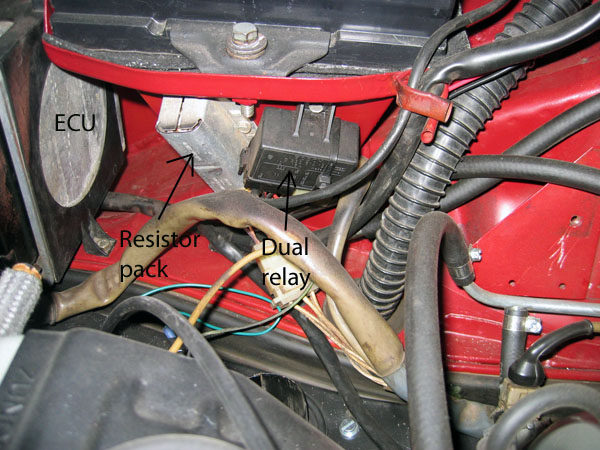
|
|
|
|
| wrightee |
Sep 2 2012, 12:42 PM
Post
#4
|
|
Member Group: Members Posts: 83 Joined: 18-November 09 From: Montclair, VA Member No.: 11,053 Region Association: MidAtlantic Region |
QUOTE(jsayre914 @ Sep 2 2012, 02:36 PM)  Thanks, guys...I have been wondering about that piece, as the plastic plug is badly corroded from battery acid, but it appears that the spades are still making good contact - I'll give them a closer look and try cleaning them up a bit more. |
|
|
|
| wrightee |
Sep 2 2012, 01:01 PM
Post
#5
|
|
Member Group: Members Posts: 83 Joined: 18-November 09 From: Montclair, VA Member No.: 11,053 Region Association: MidAtlantic Region |
[quote name='wrightee' date='Sep 2 2012, 02:42 PM' post='1732801']
[quote name='jsayre914' post='1732799' date='Sep 2 2012, 02:36 PM'] (IMG:style_emoticons/default/agree.gif) I had 3 out of 4 wires break on the resistor pack. Check it [/quote] Resister connections are all solid - like I said before, the plastic plug is pretty ugly due to battery acid corrosion, but all of the spades make solid connections and all wires are intact. |
|
|
|
| jsayre914 |
Sep 2 2012, 01:06 PM
Post
#6
|
|
Speed Up !!! Group: Members Posts: 3,210 Joined: 10-February 08 From: Timonium MD 21093 Member No.: 8,696 Region Association: MidAtlantic Region |
you should be looking where the wires are solderd to the tubes inside the metal housing, this is where they snap off. not at the wire connections
|
|
|
|
| jsayre914 |
Sep 2 2012, 01:08 PM
Post
#7
|
|
Speed Up !!! Group: Members Posts: 3,210 Joined: 10-February 08 From: Timonium MD 21093 Member No.: 8,696 Region Association: MidAtlantic Region |
heres an example
Attached image(s) 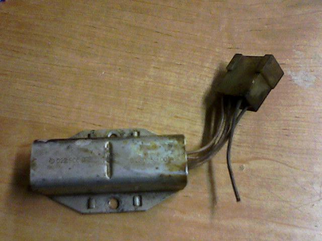
|
|
|
|
| wrightee |
Sep 2 2012, 01:29 PM
Post
#8
|
|
Member Group: Members Posts: 83 Joined: 18-November 09 From: Montclair, VA Member No.: 11,053 Region Association: MidAtlantic Region |
Wires are all connected - though I can see two that are beginning to "wear", but are still 80% intact (a few strands on the side are broken, but not enough to keep the current from flowing).
While I don't believe this is the source of the non-start issue, I will put this on the list to replace due to the wear...anyone have any idea if the harness side plugs are available anywhere? |
|
|
|
| timothy_nd28 |
Sep 2 2012, 01:55 PM
Post
#9
|
|
Advanced Member Group: Members Posts: 2,299 Joined: 25-September 07 From: IN Member No.: 8,154 Region Association: Upper MidWest |
Okay, reconnect everything that you had removed. Let's start at the beginning.
Now pull the main ECU/brain connector off. We will test these injectors manually, without pulling them or having a noid light. With this massive connector off of the brain, obtain a small length of wire. Ground one side of this wire to either chassis ground or the negative post on the battery. Locate at the ECU connector pins 14,32,33 and 15. With the ignition switch to the "key on" position, go ahead and ground pin 14. You should hear a click from one of the injectors. After you verified an audible click, go ahead and ground pin 32 and listen for the same results. Do the same procedure for pin 33 and 15. These are your 4 fuel injectors. If you have audible clicks on each injector, it proves that your resistor pack is working, and part of your dual relay. When performing this test, be sure to not leave your ignition switch to the "on" position for very long. You will damage your points or coil. 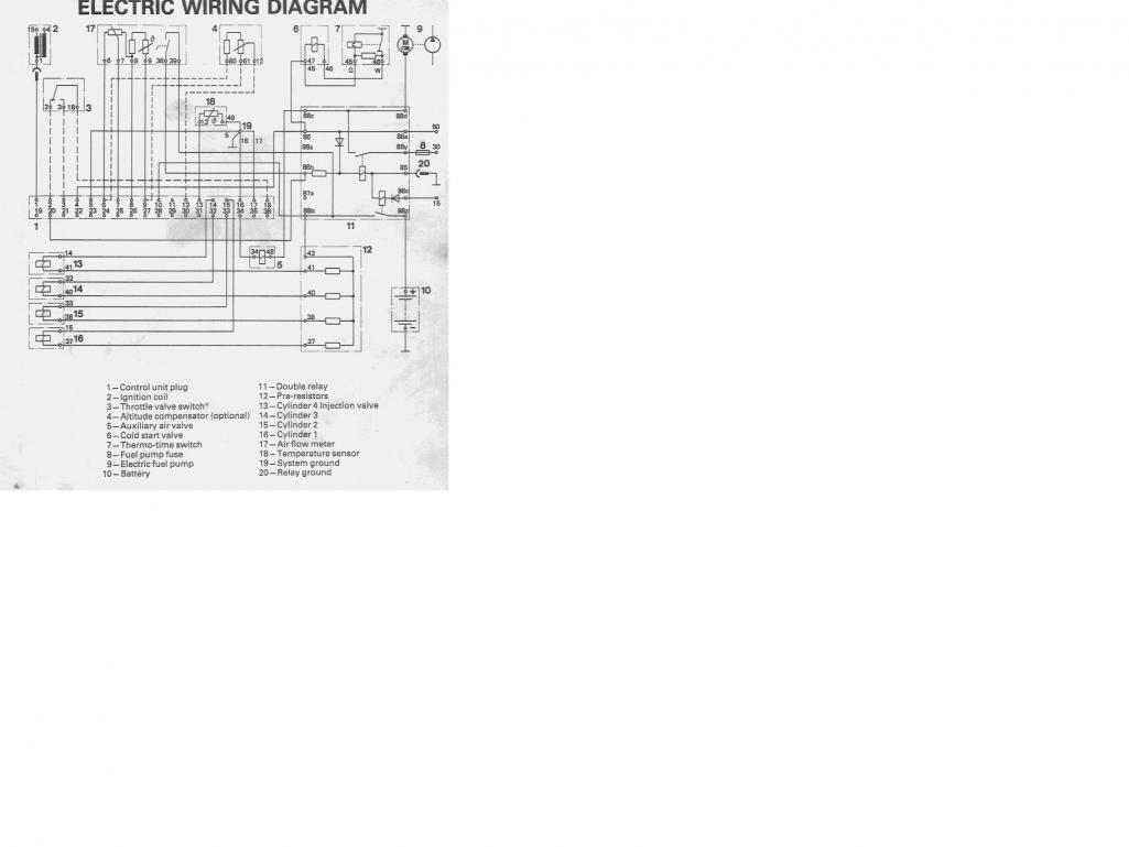 |
|
|
|
| wrightee |
Sep 2 2012, 02:52 PM
Post
#10
|
|
Member Group: Members Posts: 83 Joined: 18-November 09 From: Montclair, VA Member No.: 11,053 Region Association: MidAtlantic Region |
Thanks Tim,
I did not hear any clicks after testing at each of these pins. |
|
|
|
| Black22 |
Sep 2 2012, 03:04 PM
Post
#11
|
|
Senior Member Group: Members Posts: 886 Joined: 1-November 07 From: Creswell, OR Member No.: 8,290 Region Association: Pacific Northwest |
I'll let the pro handle this...Tim_nd helped me out a while back. He knows his L-jet!
Good luck! |
|
|
|
| timothy_nd28 |
Sep 2 2012, 03:45 PM
Post
#12
|
|
Advanced Member Group: Members Posts: 2,299 Joined: 25-September 07 From: IN Member No.: 8,154 Region Association: Upper MidWest |
Check pin 88z at the dual relay, you should have 12vdc hot at all times, doesn't matter if your key is on or off. For this test, you can go ahead and disconnect the relay from the connector, or you can slightly pull the connector away from the relay so that you can try to sneak a meter lead to 88z.
If you have 12vdc present, then check pin 88b with the ignition switch to the "on" position (relay must be inserted) . If you have 12vdc present on pin 88b, you should also have 12vdc present on pin 10 on the main ECU connector. |
|
|
|
| wrightee |
Sep 2 2012, 04:12 PM
Post
#13
|
|
Member Group: Members Posts: 83 Joined: 18-November 09 From: Montclair, VA Member No.: 11,053 Region Association: MidAtlantic Region |
QUOTE(tim_nd @ Sep 2 2012, 05:45 PM) Check pin 88z at the dual relay, you should have 12vdc hot at all times, doesn't matter if your key is on or off. For this test, you can go ahead and disconnect the relay from the connector, or you can slightly pull the connector away from the relay so that you can try to sneak a meter lead to 88z. If you have 12vdc present, then check pin 88b with the ignition switch to the "on" position (relay must be inserted) . If you have 12vdc present on pin 88b, you should also have 12vdc present on pin 10 on the main ECU connector. Ok, those all check out - 88z has power w/o key in, 88b good with key at "on" and power at pin 10 on the ECU as well. |
|
|
|
| timothy_nd28 |
Sep 2 2012, 04:46 PM
Post
#14
|
|
Advanced Member Group: Members Posts: 2,299 Joined: 25-September 07 From: IN Member No.: 8,154 Region Association: Upper MidWest |
Excellent, I think we are homing into the problem area. With the key "on" check the common pin on the resistor pack. I believe it's the top middle pin. Leave the the resistor pack plugged in. The common pin will have one wire running back towards the ass end of the resistor pack. This pin should have 12vdc present, as this is the same wire of 88b on the relay connector you tested earlier.
If there is 12vdc present on the common pin on the resistor pack, go ahead and measure voltages on every other pin on that resistor pack connector (resistor pack still connected) |
|
|
|
| wrightee |
Sep 2 2012, 05:15 PM
Post
#15
|
|
Member Group: Members Posts: 83 Joined: 18-November 09 From: Montclair, VA Member No.: 11,053 Region Association: MidAtlantic Region |
QUOTE(tim_nd @ Sep 2 2012, 06:46 PM) Excellent, I think we are homing into the problem area. With the key "on" check the common pin on the resistor pack. I believe it's the top middle pin. Leave the the resistor pack plugged in. The common pin will have one wire running back towards the ass end of the resistor pack. This pin should have 12vdc present, as this is the same wire of 88b on the relay connector you tested earlier. If there is 12vdc present on the common pin on the resistor pack, go ahead and measure voltages on every other pin on that resistor pack connector (resistor pack still connected) I'm getting 12vdc on all 5 pins. |
|
|
|
| Dave_Darling |
Sep 2 2012, 05:30 PM
Post
#16
|
|
914 Idiot Group: Members Posts: 15,355 Joined: 9-January 03 From: Silicon Valley / Kailua-Kona Member No.: 121 Region Association: Northern California |
Do you have the white wire connected to the coil (-) terminal?
--DD |
|
|
|
| timothy_nd28 |
Sep 2 2012, 05:35 PM
Post
#17
|
|
Advanced Member Group: Members Posts: 2,299 Joined: 25-September 07 From: IN Member No.: 8,154 Region Association: Upper MidWest |
Okay, measure the voltages on the ECU connector at pins: 14 to gnd, 15 to gnd, 32 to gnd, and 33 to gnd.
|
|
|
|
| wrightee |
Sep 2 2012, 05:50 PM
Post
#18
|
|
Member Group: Members Posts: 83 Joined: 18-November 09 From: Montclair, VA Member No.: 11,053 Region Association: MidAtlantic Region |
QUOTE(Dave_Darling @ Sep 2 2012, 07:30 PM) Do you have the white wire connected to the coil (-) terminal? --DD Yes, white wire is on neg side. This car has a "CompuFire" ignition in place of points. |
|
|
|
| wrightee |
Sep 2 2012, 06:28 PM
Post
#19
|
|
Member Group: Members Posts: 83 Joined: 18-November 09 From: Montclair, VA Member No.: 11,053 Region Association: MidAtlantic Region |
QUOTE(tim_nd @ Sep 2 2012, 07:35 PM) Okay, measure the voltages on the ECU connector at pins: 14 to gnd, 15 to gnd, 32 to gnd, and 33 to gnd. 14 = .03 15 = 0 (nothing) 32 = 12vdc 33 = .03 BTW, I really appreciate you taking the time to walk me through this. |
|
|
|
| timothy_nd28 |
Sep 2 2012, 06:50 PM
Post
#20
|
|
Advanced Member Group: Members Posts: 2,299 Joined: 25-September 07 From: IN Member No.: 8,154 Region Association: Upper MidWest |
No prob,,all of those pins should have 12vdc. I've made a couple of assumptions here, so don't get offended. Are all the fuel injector connectors plugged onto each injector? We know one is plugged in, and making continuity,,this is why your measuring 12vdc at the ECU connector.
With the one pin on the ECU connector reading 12vdc on the previous test,,if you apply ground on that pin, do you hear a click? I would suggest pulling off each injector lead, then re-seating each connector with a slight wiggle, to ensure a good electrical connection. Then retest those pins at the ECU plug to see if you have any more 12vdc pins. If you have the same results, (one out of 4 has 12vdc),,then pull off each injector lead and probe one of the 2 contacts. With the ECU plug still unattached,,,one contact will measure nothing (at the fuel injector connector) the other should be reading 12vdc. |
|
|
|
|
1 User(s) are reading this topic (1 Guests and 0 Anonymous Users)
0 Members:

|
Lo-Fi Version | Time is now: 9th July 2026 - 01:23 PM |
Invision Power Board
v9.1.4 © 2026 IPS, Inc.