|
|
|
Porsche, and the Porsche crest are registered trademarks of Dr. Ing. h.c. F. Porsche AG.
This site is not affiliated with Porsche in any way. Its only purpose is to provide an online forum for car enthusiasts. All other trademarks are property of their respective owners. |
|
|

  |

| timothy_nd28 |
 Oct 18 2012, 03:13 PM Oct 18 2012, 03:13 PM
Post
#21
|
|
Advanced Member  Group: Members Posts: 2,299 Joined: 25-September 07 From: IN Member No.: 8,154 Region Association: Upper MidWest |
I'll reply later tonight, I have Bio Statistics class in 20 mins. (IMG:style_emoticons/default/beerchug.gif)
|
   |

 
|
| timothy_nd28 |
Oct 18 2012, 05:48 PM
Post
#22
|
|
Advanced Member Group: Members Posts: 2,299 Joined: 25-September 07 From: IN Member No.: 8,154 Region Association: Upper MidWest |
The dual relay could of been jumped out for various reasons, but for now remove that jumper wire.
That jumper was most likely jumping 86c to 88d, which is switched ignition 12vdc power on pin 86c and 88d is the fuel pump pin. The problem I have with this setup would be running fuel pump current thru the ignition switch. The ignition switch will most likely fail before too long by running high current thru its contacts. It's far better for the ignition switch to drive a small coil, versus a power hungry fuel pump. So, with that jumper removed, look at the 2 square connectors that plug into the double relay. Inspect the pins within the connector for corrosion, also make sure the pins are seated within the plastic molex connector. Next, locate your Air Flow Meter, and remove the flat electrical connector. Now study the pins on the AFM. You will be looking for pin 36 and pin 39. After finding these 2 pins, probe these 2 pins with your multimeter (set for resistance). Initially, you will see a reading of OL or infinity on the meter. Next, if you remove the air filter, you can sneak a screw driver inside to push a metal flap inside the AFM. With an extra set of hands, one person measure the resistance on pin 36 and pin 39, while the other person pushes on the flap. With the flap deflected, you should read close to 0 ohms. Next, inspect the AFM flap, it should move freely and spring back. If your 914 backfired, due to a vacuum leak, this can cause the AFM flap to warp. If the flap warps, it won't move and will hang up. Now set your multimeter to the DC voltage setting and reinstall the flat electrical connector back on the AFM, and then turn your attention back to the 2 connectors that plug into your dual relay. (make sure the dual relay isn't installed and that jumper has been removed) Your black meter lead, find a place to ground it somewhere on the battery or chassis. Find pin 86a on your connector (not the dual relay), and insert your red meter lead. Turn the ignition on, you should have 0 volts dc, however if you turn the key to the "start" position, you should see 12vdc. You may need someone to help you turn the key while your watching the multimeter. Next, find 86b on the connector, and put your red meter lead in that slot. With the ignition on (not start), you should be seeing 0vdc. Reach over and nudge that AFM flap (make sure the connector on the AFM is reinstalled). As you move the AFM flap, you should see 12vdc. This is a good start, try this and let us know what you get. |
|
|
|
| timothy_nd28 |
Oct 18 2012, 07:24 PM
Post
#23
|
|
Advanced Member Group: Members Posts: 2,299 Joined: 25-September 07 From: IN Member No.: 8,154 Region Association: Upper MidWest |
Minor screw up, that last test pertaining to you testing pin 86b for voltage. You will not see voltage while performing this test, with the dual relay not inserted.
So, before probing pin 86b for voltage, I'll need you to build a small jumper wire. Attach one side of the jumper wire to the positive side of the battery. The other side of the jumper needs to go in slot 88a. After adding this temporary jumper, probe pin 86b for voltage when you deflect the AFM flap. Be certain that 86b has 0 voltage when the AFM flap is at its resting state. sorry for the mix up. |
|
|
|
| Oregon74 |
Oct 18 2012, 10:11 PM
Post
#24
|
|
Newbie Group: Members Posts: 44 Joined: 13-October 12 From: Oregon Member No.: 15,035 Region Association: None |
QUOTE(timothy_nd28 @ Oct 18 2012, 06:24 PM)  Minor screw up, that last test pertaining to you testing pin 86b for voltage. You will not see voltage while performing this test, with the dual relay not inserted. So, before probing pin 86b for voltage, I'll need you to build a small jumper wire. Attach one side of the jumper wire to the positive side of the battery. The other side of the jumper needs to go in slot 88a. After adding this temporary jumper, probe pin 86b for voltage when you deflect the AFM flap. Be certain that 86b has 0 voltage when the AFM flap is at its resting state. sorry for the mix up. Thanks so much. I'll print this out and report back. Can't thank you enough JAA |
|
|
|
| timothy_nd28 |
Oct 18 2012, 11:34 PM
Post
#25
|
|
Advanced Member Group: Members Posts: 2,299 Joined: 25-September 07 From: IN Member No.: 8,154 Region Association: Upper MidWest |
Your welcome and it's my pleasure! (IMG:style_emoticons/default/beerchug.gif) I know we have deviated from your original problem, but what you have found needs to be fixed pronto.
Here are some pictures from the Ljet manual to help aid you tomorrow. One last thing, when testing with the ignition switch turned to the "on" position, be mindful to not leave it on too long. You can ruin your points or your pointless module if you have one. It may be safer to temporarily remove the negative wire from your distributor to the ignition coil. 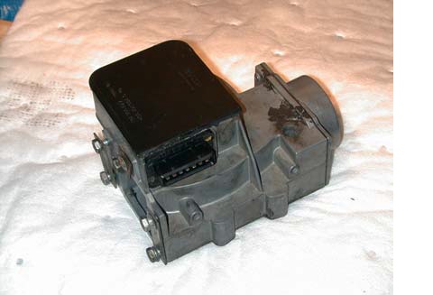 your Airflow meter 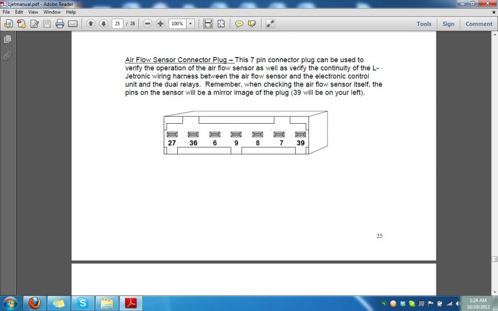 this is the pinout for the connector that plugs into the AFM 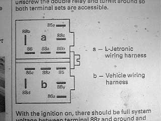 The pinout for the double relay or dual relay. |
|
|
|
| Cap'n Krusty |
Oct 19 2012, 08:15 AM
Post
#26
|
|
Cap'n Krusty Group: Members Posts: 10,794 Joined: 24-June 04 From: Santa Maria, CA Member No.: 2,246 Region Association: Central California |
Anyone here wishing to have a PDF of the original VW L-jet troubleshooting manual should send me a request for one. Warning!: It's a large file and you MUST send me an e-mail address that can/will accept it. You get ONE shot at it, 'cause I don't have the time to waste making multiple efforts to send it to you. Send requests to trannysocket (at) gmail.com. (note the address is spamproofed to some extent, so fix it for use).
The Cap'n |
|
|
|
| Oregon74 |
Oct 19 2012, 10:05 AM
Post
#27
|
|
Newbie Group: Members Posts: 44 Joined: 13-October 12 From: Oregon Member No.: 15,035 Region Association: None |
QUOTE(Cap'n Krusty @ Oct 19 2012, 07:15 AM) Anyone here wishing to have a PDF of the original VW L-jet troubleshooting manual should send me a request for one. Warning!: It's a large file and you MUST send me an e-mail address that can/will accept it. You get ONE shot at it, 'cause I don't have the time to waste making multiple efforts to send it to you. Send requests to trannysocket (at) gmail.com. (note the address is spamproofed to some extent, so fix it for use). The Cap'n I can't believe how helpful everyone here is. I work in public service and let me tell you America would be better if politicians were like the folks on 914 world helping me. JAA I'd love the PDF jallmand@mac.com |
|
|
|
| zonedoubt |
Oct 19 2012, 12:24 PM
Post
#28
|
|
Canadian Member Group: Members Posts: 668 Joined: 14-May 03 From: Vancouver, BC Member No.: 696 Region Association: Canada |
Here's a nice write-up on how the dual relay works: http://www.ratwell.com/technical/DoubleRelay.html
|
|
|
|
| Oregon74 |
Oct 19 2012, 06:35 PM
Post
#29
|
|
Newbie Group: Members Posts: 44 Joined: 13-October 12 From: Oregon Member No.: 15,035 Region Association: None |
QUOTE(zonedoubt @ Oct 19 2012, 11:24 AM) Here's a nice write-up on how the dual relay works: http://www.ratwell.com/technical/DoubleRelay.html Hello everyone---- this has been great and I've learned more than I ever expected- or planned on- but I do enjoy it. So I started digging into the relay issue and it appeared to me that whoever short-wired etc really tinkered around in moved wires all over the place. The more I looked, many leads went nowhere. So I thought I'd try to map it all out. For a non-electrican this has been a task. I have since learned that Bosch 0 332 514 120 was for the bus. 0 332 514 121 - according to my local import VW cool guy shop is for the 914. Is he right? I brought it home just incase, but now the wiring diagrams don't seem to jive. JAA |
|
|
|
| timothy_nd28 |
Oct 19 2012, 07:39 PM
Post
#30
|
|
Advanced Member Group: Members Posts: 2,299 Joined: 25-September 07 From: IN Member No.: 8,154 Region Association: Upper MidWest |
I'm gonna need some more info on what your seeing. You have wires that are cut? If so, which pin does it correlate to on the dual relay connector? How many wires are we talking about? How about some pictures.
|
|
|
|
| Black22 |
Oct 19 2012, 07:52 PM
Post
#31
|
|
Senior Member Group: Members Posts: 886 Joined: 1-November 07 From: Creswell, OR Member No.: 8,290 Region Association: Pacific Northwest |
My 1974 1.8l uses the 0 332 514 120 part numbered relay.
I think your guy is wrong? You can verify this on the Pelican Parts website. |
|
|
|
| Oregon74 |
Oct 20 2012, 09:16 AM
Post
#32
|
|
Newbie Group: Members Posts: 44 Joined: 13-October 12 From: Oregon Member No.: 15,035 Region Association: None |
QUOTE(timothy_nd28 @ Oct 19 2012, 06:39 PM) I'm gonna need some more info on what your seeing. You have wires that are cut? If so, which pin does it correlate to on the dual relay connector? How many wires are we talking about? How about some pictures. Pictures enclosed 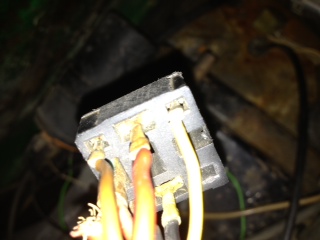 |
|
|
|
| Oregon74 |
Oct 20 2012, 09:17 AM
Post
#33
|
|
Newbie Group: Members Posts: 44 Joined: 13-October 12 From: Oregon Member No.: 15,035 Region Association: None |
QUOTE(Oregon74 @ Oct 20 2012, 08:16 AM) QUOTE(timothy_nd28 @ Oct 19 2012, 06:39 PM) I'm gonna need some more info on what your seeing. You have wires that are cut? If so, which pin does it correlate to on the dual relay connector? How many wires are we talking about? How about some pictures. Pictures enclosed Attached image(s) 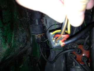
|
|
|
|
| Oregon74 |
Oct 20 2012, 09:19 AM
Post
#34
|
|
Newbie Group: Members Posts: 44 Joined: 13-October 12 From: Oregon Member No.: 15,035 Region Association: None |
QUOTE(Oregon74 @ Oct 20 2012, 08:17 AM) QUOTE(Oregon74 @ Oct 20 2012, 08:16 AM) QUOTE(timothy_nd28 @ Oct 19 2012, 06:39 PM) I'm gonna need some more info on what your seeing. You have wires that are cut? If so, which pin does it correlate to on the dual relay connector? How many wires are we talking about? How about some pictures. Pictures enclosed Attached image(s) 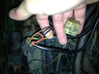
|
|
|
|
| timothy_nd28 |
Oct 20 2012, 01:40 PM
Post
#35
|
|
Advanced Member Group: Members Posts: 2,299 Joined: 25-September 07 From: IN Member No.: 8,154 Region Association: Upper MidWest |
QUOTE So I started digging into the relay issue and it appeared to me that whoever short-wired etc really tinkered around in moved wires all over the place. The more I looked, many leads went nowhere. So I thought I'd try to map it all out. For a non-electrican this has been a task. (IMG:style_emoticons/default/confused24.gif) I'm not seeing the many leads going to nowhere as you stated earlier. I maybe see one wire that is frayed or not connected. 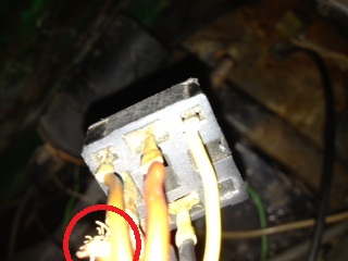 The black connector plugs into the dual relay, and serves the ignition side. The white connector plugs into the same dual relay, and serves your FI side. The white FI connector looks pretty corroded, you should soak that connector in a glass of Coke for an hour. The only thing that I can see wrong with that black connector is possibly a missing or frayed wire in that picture (I circled what I think the problem area is in red). Is there a terminal in the black plastic connector housing that happens to have a electrical connector in the slot, but no wire going to it? If I counted the wires in the schematic correctly, you should have 8 white wires going to the FI connector (white connector) some wires may be doubled up on the same terminal. Whereas the black connector (ignition connector) there should be 5 wires, varying in color. The schematic doesn't show any wires doubled up on the ignition connector, but its possible your 75 914 can be different than the 74 schematic. I wish I had my 914 here at my house, but I let my brother borrow it for a couple of weeks. If you have a wire connector in the connector slot that's missing a wire, let me know what pin it is. Look under your dual relay, and you will see tiny numbers. Line up the dual relay with the connector and tell me what pin numbers are missing a wire if any. If you have loose wires that are taped off or not going to anywhere, tell me what color wire it is and the thickness of the wire. Nonetheless, I don't see anything crying out from your pictures other than a corroded connector, and possible a frayed wire that maybe fell off its terminal. |
|
|
|
| Oregon74 |
Oct 20 2012, 04:57 PM
Post
#36
|
|
Newbie Group: Members Posts: 44 Joined: 13-October 12 From: Oregon Member No.: 15,035 Region Association: None |
QUOTE(timothy_nd28 @ Oct 20 2012, 12:40 PM) QUOTE So I started digging into the relay issue and it appeared to me that whoever short-wired etc really tinkered around in moved wires all over the place. The more I looked, many leads went nowhere. So I thought I'd try to map it all out. For a non-electrican this has been a task. (IMG:style_emoticons/default/confused24.gif) I'm not seeing the many leads going to nowhere as you stated earlier. I maybe see one wire that is frayed or not connected. The black connector plugs into the dual relay, and serves the ignition side. The white connector plugs into the same dual relay, and serves your FI side. The white FI connector looks pretty corroded, you should soak that connector in a glass of Coke for an hour. The only thing that I can see wrong with that black connector is possibly a missing or frayed wire in that picture (I circled what I think the problem area is in red). Is there a terminal in the black plastic connector housing that happens to have a electrical connector in the slot, but no wire going to it? If I counted the wires in the schematic correctly, you should have 8 white wires going to the FI connector (white connector) some wires may be doubled up on the same terminal. Whereas the black connector (ignition connector) there should be 6 wires, varying in color. The schematic doesn't show any wires doubled up on the ignition connector, but its possible your 75 914 can be different than the 74 schematic. I wish I had my 914 here at my house, but I let my brother borrow it for a couple of weeks. If you have a wire connector in the connector slot that's missing a wire, let me know what pin it is. Look under your dual relay, and you will see tiny numbers. Line up the dual relay with the connector and tell me what pin numbers are missing a wire if any. If you have loose wires that are taped off or not going to anywhere, tell me what color wire it is and the thickness of the wire. Nonetheless, I don't see anything crying out from your pictures other than a corroded connector, and possible a frayed wire that maybe fell off its terminal. Attached image(s) 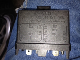 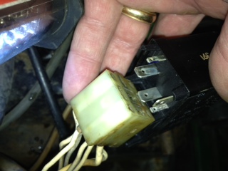 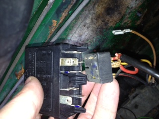 
|
|
|
|
| Oregon74 |
Oct 20 2012, 05:00 PM
Post
#37
|
|
Newbie Group: Members Posts: 44 Joined: 13-October 12 From: Oregon Member No.: 15,035 Region Association: None |
QUOTE(Oregon74 @ Oct 20 2012, 03:57 PM) QUOTE(timothy_nd28 @ Oct 20 2012, 12:40 PM) QUOTE So I started digging into the relay issue and it appeared to me that whoever short-wired etc really tinkered around in moved wires all over the place. The more I looked, many leads went nowhere. So I thought I'd try to map it all out. For a non-electrican this has been a task. (IMG:style_emoticons/default/confused24.gif) I'm not seeing the many leads going to nowhere as you stated earlier. I maybe see one wire that is frayed or not connected. The black connector plugs into the dual relay, and serves the ignition side. The white connector plugs into the same dual relay, and serves your FI side. The white FI connector looks pretty corroded, you should soak that connector in a glass of Coke for an hour. The only thing that I can see wrong with that black connector is possibly a missing or frayed wire in that picture (I circled what I think the problem area is in red). Is there a terminal in the black plastic connector housing that happens to have a electrical connector in the slot, but no wire going to it? If I counted the wires in the schematic correctly, you should have 8 white wires going to the FI connector (white connector) some wires may be doubled up on the same terminal. Whereas the black connector (ignition connector) there should be 6 wires, varying in color. The schematic doesn't show any wires doubled up on the ignition connector, but its possible your 75 914 can be different than the 74 schematic. I wish I had my 914 here at my house, but I let my brother borrow it for a couple of weeks. If you have a wire connector in the connector slot that's missing a wire, let me know what pin it is. Look under your dual relay, and you will see tiny numbers. Line up the dual relay with the connector and tell me what pin numbers are missing a wire if any. If you have loose wires that are taped off or not going to anywhere, tell me what color wire it is and the thickness of the wire. Nonetheless, I don't see anything crying out from your pictures other than a corroded connector, and possible a frayed wire that maybe fell off its terminal. Tim- Here is a picture of the relay. How the left side goes in. Yes, 8 wires. Not all leads connect to the tab on the relay. The right side how it goes in. Note the brown wire is the fuel pump. Not connected. Another angle of the right side where the wires go in All Coke cleaned |
|
|
|
| timothy_nd28 |
Oct 20 2012, 05:02 PM
Post
#38
|
|
Advanced Member Group: Members Posts: 2,299 Joined: 25-September 07 From: IN Member No.: 8,154 Region Association: Upper MidWest |
black connector, pin 85 should be the brown ground wire
|
|
|
|
| timothy_nd28 |
Oct 20 2012, 05:05 PM
Post
#39
|
|
Advanced Member Group: Members Posts: 2,299 Joined: 25-September 07 From: IN Member No.: 8,154 Region Association: Upper MidWest |
Pin 88d is your fuel pump wire on the black ignition connector. The 88d wire should be red/green,,this drives your fuel pump
|
|
|
|
| Oregon74 |
Oct 20 2012, 05:16 PM
Post
#40
|
|
Newbie Group: Members Posts: 44 Joined: 13-October 12 From: Oregon Member No.: 15,035 Region Association: None |
QUOTE(timothy_nd28 @ Oct 20 2012, 04:02 PM) black connector, pin 85 should be the brown ground wire Cool Brown is ground I have yellow to 85 right side of the 3rd pic 88f is that red duallydo thingy someone made middle of the relay 88b the other end of the red wire 88e empty 88c empty left side of the relay 86 black wire 88a red and black wire 86b empty Attached image(s) 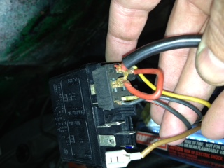
|
|
|
|
|
1 User(s) are reading this topic (1 Guests and 0 Anonymous Users)
0 Members:

|
Lo-Fi Version | Time is now: 28th May 2024 - 01:23 PM |
Invision Power Board
v9.1.4 © 2024 IPS, Inc.