|
|
|
Porsche, and the Porsche crest are registered trademarks of Dr. Ing. h.c. F. Porsche AG.
This site is not affiliated with Porsche in any way. Its only purpose is to provide an online forum for car enthusiasts. All other trademarks are property of their respective owners. |
|
|

  |

| 76-914 |
 Jan 16 2014, 02:51 PM Jan 16 2014, 02:51 PM
Post
#221
|
|
Repeat Offender & Resident Subaru Antagonist  Group: Members Posts: 13,494 Joined: 23-January 09 From: Temecula, CA Member No.: 9,964 Region Association: Southern California |
QUOTE(Chris H. @ Jan 16 2014, 12:34 PM)  Remember I haven't DRIVEN mine but the way it is set up is: Inner CV = FEMALE Subie (2002-2004) which is fine for you because your trans already has stub axles so it's set up for female CVs Axle = Ians or re-splined 914 axle on one side to accept said Subie CV Outer = the stock 914 CV....or you could upgrade to 944 if you pop a stock CV or two. The other option is the "magic flange", which is fine too. Not sure about availability. The Subie CV is very strong so that's why I went with it. I did a poor job of documenting this part of the build but here is a terrible pic of one of mine: The Subie female CV is on the left, then the custom axle, then the 914 CV. I read on NASIOC NEVER to use the aftermarket Subie CV's. Always buy a used stock OEM CV even though they are about the same price as a new or rebuilt non OEM one. I got my axle pair for $50 and they were totally fine. Also when you do the Subie CV you don't need to lock the axle in with the lock washer...you let it float. Weird but apparently it's fine. Chris, I was under the impression the stock 914 shaft was too small to re-spline and that it req'd using a bus or 944 axle. Just want to clarify this before I get some 914 shafts. I have the stock Suby 1/2 shafts/CV's and had planned on re-using the Suby CV's. TIA |
   |

 
|
| Chris H. |
Jan 16 2014, 03:04 PM
Post
#222
|
|
Senior Member Group: Members Posts: 4,029 Joined: 2-January 03 From: Chicago 'burbs Member No.: 73 Region Association: Upper MidWest |
You may be right on that Kent...sorry I had not picked up on it before. I bought Ian's setup. Bob would know for sure and I do recall something about him mentioning bus axles...didn't know the reason but that may be what it was.
|
|
|
|
| BIGKAT_83 |
Jan 16 2014, 05:14 PM
Post
#223
|
|
Senior Member Group: Members Posts: 1,798 Joined: 25-January 03 From: Way down south Bogart,GA Member No.: 194 Region Association: South East States |
Stock 914 axles are fine. I've had 3 sets done and just found some one else to do them local.
|
|
|
|
| 76-914 |
Jan 16 2014, 06:15 PM
Post
#224
|
|
Repeat Offender & Resident Subaru Antagonist Group: Members Posts: 13,494 Joined: 23-January 09 From: Temecula, CA Member No.: 9,964 Region Association: Southern California |
Geez. How easy is that? Quite honestly my head was swimming with all I've read. Thanks guys (IMG:style_emoticons/default/pray.gif)
|
|
|
|
| BIGKAT_83 |
Jan 16 2014, 06:26 PM
Post
#225
|
|
Senior Member Group: Members Posts: 1,798 Joined: 25-January 03 From: Way down south Bogart,GA Member No.: 194 Region Association: South East States |
Stock 914 axles are fine. I've had 3 sets done and just found some one else to do them local.
|
|
|
|
| Chris H. |
Jan 17 2014, 07:38 AM
Post
#226
|
|
Senior Member Group: Members Posts: 4,029 Joined: 2-January 03 From: Chicago 'burbs Member No.: 73 Region Association: Upper MidWest |
One quick tip for ya...
If you already have female Subie CV's you just have to take them off the Subie axles. The way you do that is undo the larger end of the CV boot and peel it back a bit. The joint will be very loose then and you will be tempted to slide the axle off the female inner CV end. BUT WAIT....there is a retaining ring that you have to remove first that is in the end of the CV bell. Here's a pic: 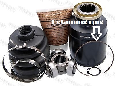 Just feel around at the lip of the open end, you'll find it. It's in there loosely, you can take it out without any tools. If you just slide the bell up without taking that out it will catch at the end. A guy I know very well just yanked at it and bent the hell out of the retaining ring before he figured out it was there. Once the two pieces are separated you will see a smaller retaining clip that holds that triple-headed bearing to the axle, just pry that sucker off and you're good. And prepare for a HUGE GREASY MESS!!! I'm sure you've done CV's before. |
|
|
|
| 76-914 |
Jan 17 2014, 09:09 AM
Post
#227
|
|
Repeat Offender & Resident Subaru Antagonist Group: Members Posts: 13,494 Joined: 23-January 09 From: Temecula, CA Member No.: 9,964 Region Association: Southern California |
QUOTE(Chris H. @ Jan 17 2014, 05:38 AM) One quick tip for ya... If you already have female Subie CV's you just have to take them off the Subie axles. The way you do that is undo the larger end of the CV boot and peel it back a bit. The joint will be very loose then and you will be tempted to slide the axle off the female inner CV end. BUT WAIT....there is a retaining ring that you have to remove first that is in the end of the CV bell. Here's a pic: Just feel around at the lip of the open end, you'll find it. It's in there loosely, you can take it out without any tools. If you just slide the bell up without taking that out it will catch at the end. A guy I know very well just yanked at it and bent the hell out of the retaining ring before he figured out it was there. Once the two pieces are separated you will see a smaller retaining clip that holds that triple-headed bearing to the axle, just pry that sucker off and you're good. And prepare for a HUGE GREASY MESS!!! I'm sure you've done CV's before. WOW! Perfect and great timing. Thx Chris. That saved me headaches and time. To quote Jeff Daniel's from the movie Dumb and Dumber, "You have totally redeemed yourself". Not that you needed redeeming. (IMG:style_emoticons/default/lol-2.gif) |
|
|
|
| 76-914 |
Jan 20 2014, 01:23 PM
Post
#228
|
|
Repeat Offender & Resident Subaru Antagonist Group: Members Posts: 13,494 Joined: 23-January 09 From: Temecula, CA Member No.: 9,964 Region Association: Southern California |
Back to the pedal assm. I found some adjustment of the clutch travel is necessary. The clutch master cylinder has a max of 1 1/8" travel and I was going past that. The fix is simple. This only takes a few min's. Chris and Doug, yours should be the same.
Loosen the jam nut then screw the pedal arm into it's receiver as far as it will go. Now check your travel. It should be 1" now. If not, adjust accordingly. Then tighten the jam nut, tightly. Now add a nut to the bottom (as shown in pic) with locktite. You could spot weld it but you may want to remove it one day.This will add some area to the end which will be stop. The floor board has an indentation that will accept this "foot" perfectly. It's hard to see in the pic's but it's there. 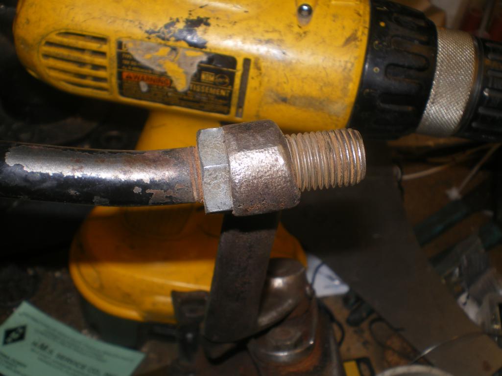 Disregard this conglomeration on the end of the pedal shaft. I discovered later that it was not needed, only one 14mm x 1.5 nut. 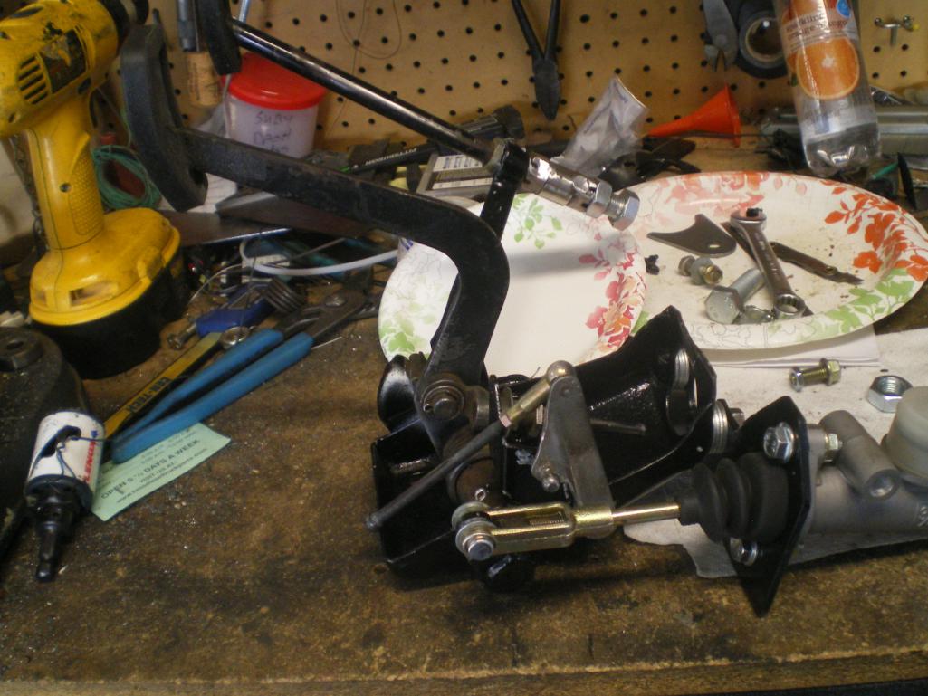 Up postion 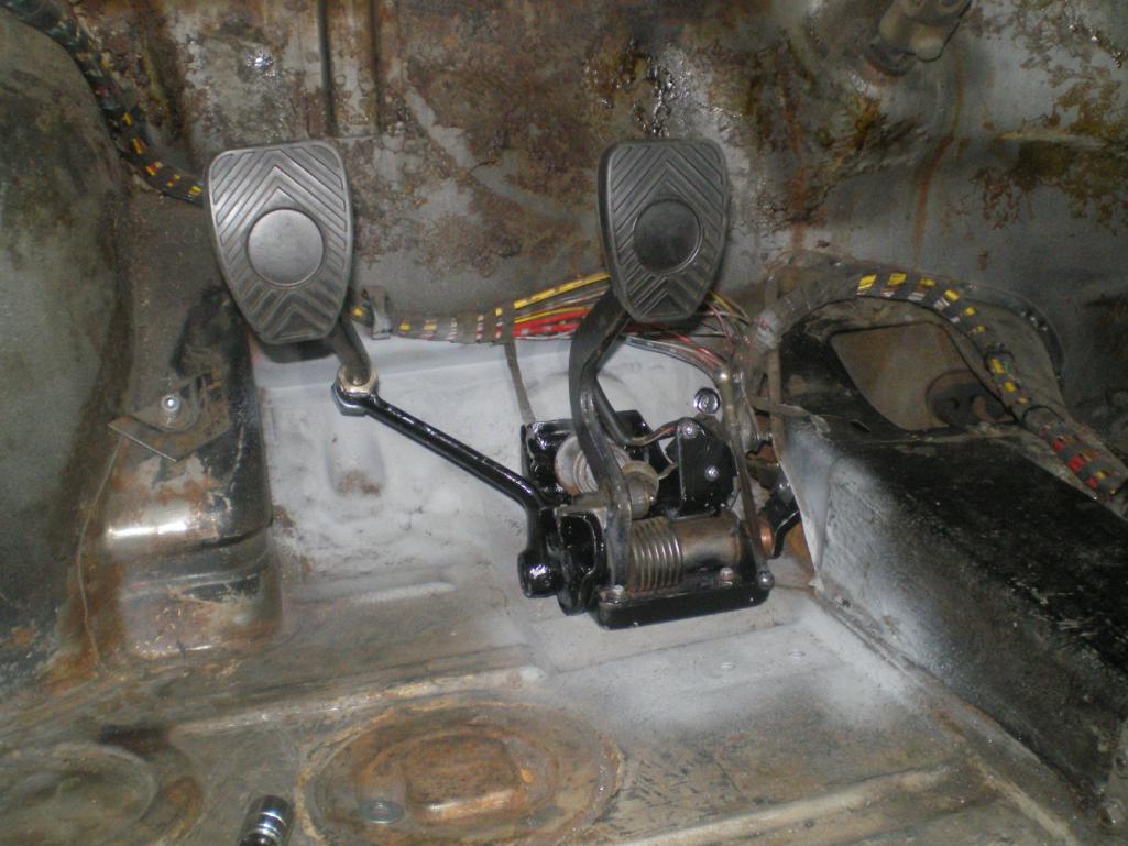 Down and seated 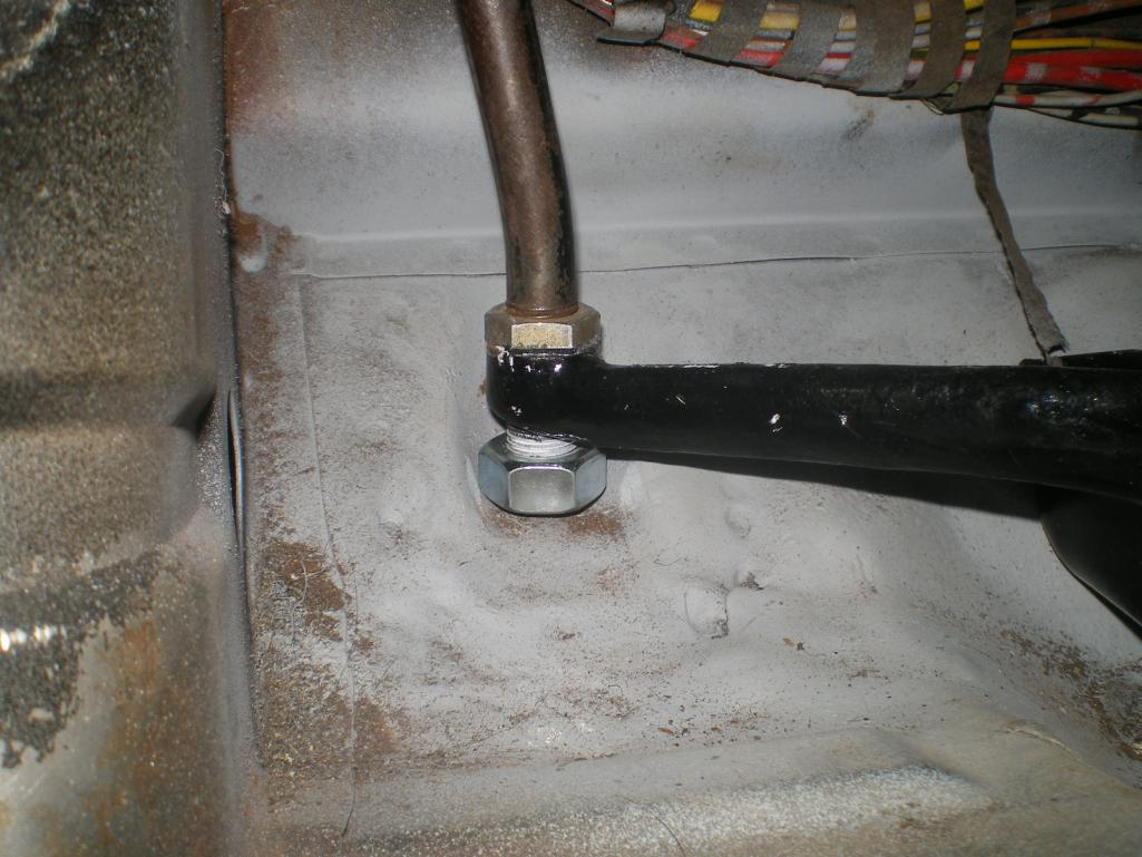 This pic shows the clevis connection (you should have about 8mm of threads protruding from the clevis. Note the washer inside the clevis. This was done to fill the void and to throw the rod a bit to the side for clearance. I trimmed the throttle piece (and IIRC so did pcar) which gives me a clean 8mm separation between clutch and throttle linkages. Notice the 19mm spacer in place of the return spring. 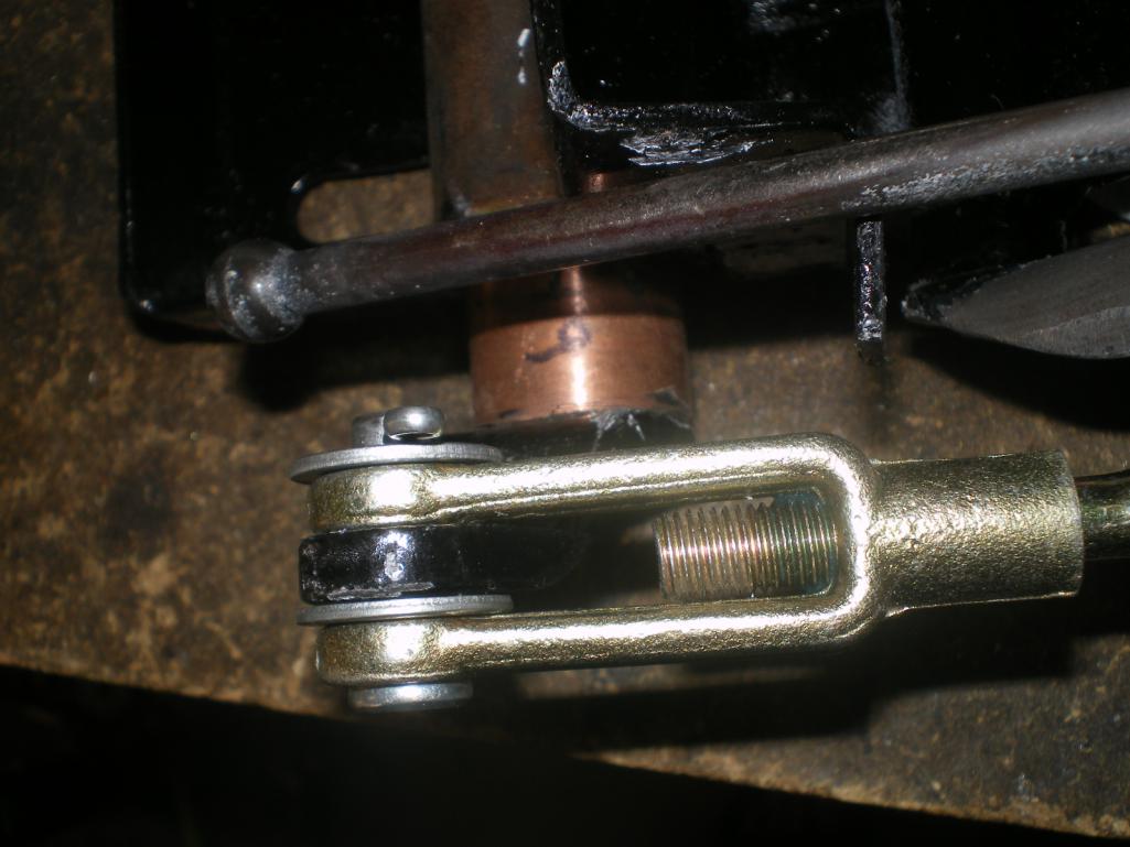 And some trimming of the throttle linkage  |
|
|
|
| skeates |
Jan 20 2014, 04:57 PM
Post
#229
|
|
Member Group: Members Posts: 218 Joined: 28-February 05 From: Sacramento, ca Member No.: 3,684 Region Association: Northern California |
It looks like you matched the master cylinder size to the stock Subaru clutch? With the Wilwood are you getting enough travel to fully disengage the clutch at the tranny? I think that the stock slave cylinder has a .75" diameter so the ratio comes out to be something like .833 and (if I've done the math correctly) that would result in a maximum of 1.1" of travel to the clutch fork. I don't know what the lever ratio is for the clutch fork so I don't know what that amounts to in terms of travel for the throw-out bearing. I'm just curious if you knew how much travel is required to full disengage the clutch? 1" seems like it should be plenty....?
p.s. I'm about to purchase a clutch master for my project and don't have a clutch to play with to get the measurements so I was hoping you might have them (IMG:style_emoticons/default/shades.gif) |
|
|
|
| 76-914 |
Jan 20 2014, 07:41 PM
Post
#230
|
|
Repeat Offender & Resident Subaru Antagonist Group: Members Posts: 13,494 Joined: 23-January 09 From: Temecula, CA Member No.: 9,964 Region Association: Southern California |
QUOTE(skeates @ Jan 20 2014, 02:57 PM) It looks like you matched the master cylinder size to the stock Subaru clutch? With the Wilwood are you getting enough travel to fully disengage the clutch at the tranny? I think that the stock slave cylinder has a .75" diameter so the ratio comes out to be something like .833 and (if I've done the math correctly) that would result in a maximum of 1.1" of travel to the clutch fork. I don't know what the lever ratio is for the clutch fork so I don't know what that amounts to in terms of travel for the throw-out bearing. I'm just curious if you knew how much travel is required to full disengage the clutch? 1" seems like it should be plenty....? p.s. I'm about to purchase a clutch master for my project and don't have a clutch to play with to get the measurements so I was hoping you might have them (IMG:style_emoticons/default/shades.gif) The Wilwood master is 3/4" also. Everything is theory, now. ChrisH should have his connected in another week or so and maybe he can video the actual combination at work. What measurements do you need. I'm a notorious procrastinator and might take several days. |
|
|
|
| skeates |
Jan 20 2014, 09:37 PM
Post
#231
|
|
Member Group: Members Posts: 218 Joined: 28-February 05 From: Sacramento, ca Member No.: 3,684 Region Association: Northern California |
I guess I'm looking for the distance that the slave cylinder needs to travel in order to disengage the clutch. On mine I don't have a clutch or pressure plate yet so I can't make any measurements except to note that the clutch fork has easily 2" of travel (about 1 inch in either direction).
Sounds like you will have a one to one rato on your system which will give you almost 1.5". I imagine that will be plenty. I'm just paranoid about getting the wrong size without doing the math. |
|
|
|
| 76-914 |
Feb 6 2014, 11:39 PM
Post
#232
|
|
Repeat Offender & Resident Subaru Antagonist Group: Members Posts: 13,494 Joined: 23-January 09 From: Temecula, CA Member No.: 9,964 Region Association: Southern California |
The 7/8" hose arrived today and the 3/4" will be here Friday. I had resigned myself to running the hose beneath the car but the more I thought about it the more I convinced myself I can do this as originally planned; thru the longs. I used this old 2" wet vac hose for a couple of things. First was to thread the pull line thru the long so I ran the rope thru the hose and this plug with a knot in the end.
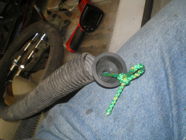 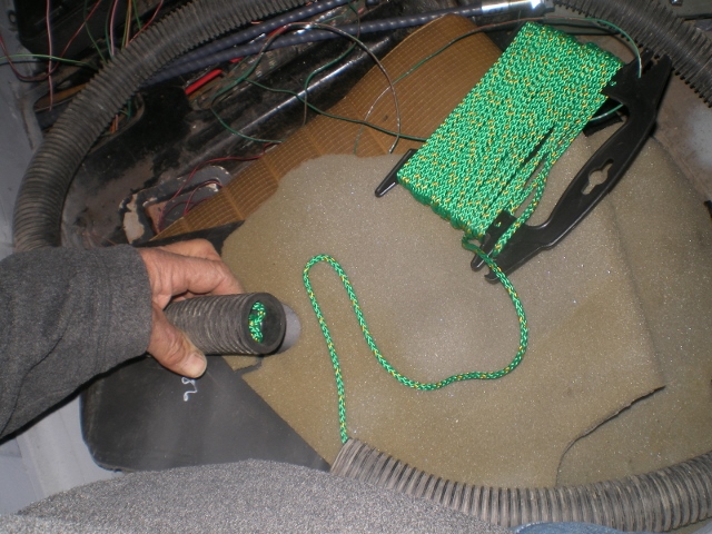 Started in the cabin and by gently pushing and twisting the vac hose it passes easily thru the long. 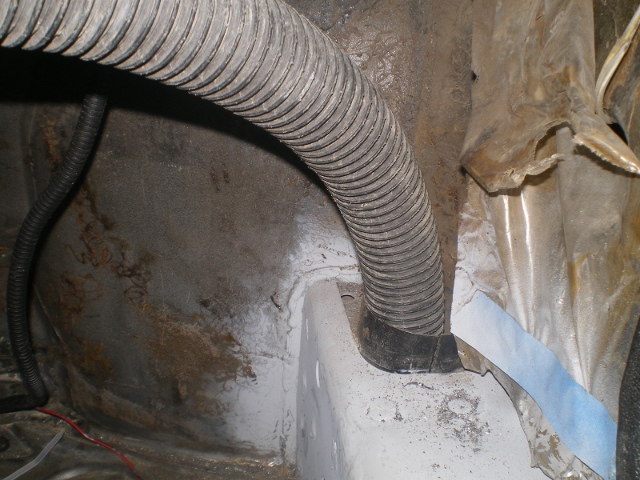 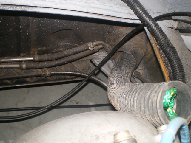 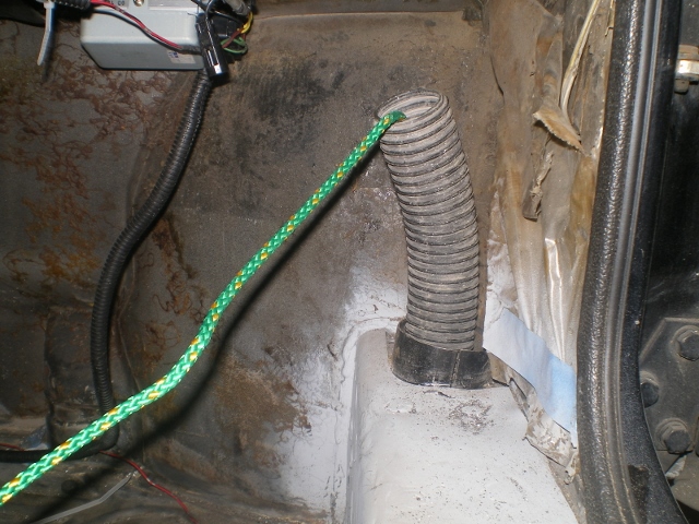 Then I tied one end of the rope in the cabin and pulled the vac hose out thru the engine compartment leaving only the line inside the long. After I drilled a small hole in the end of the hose I threaded the pull line thru the hose. 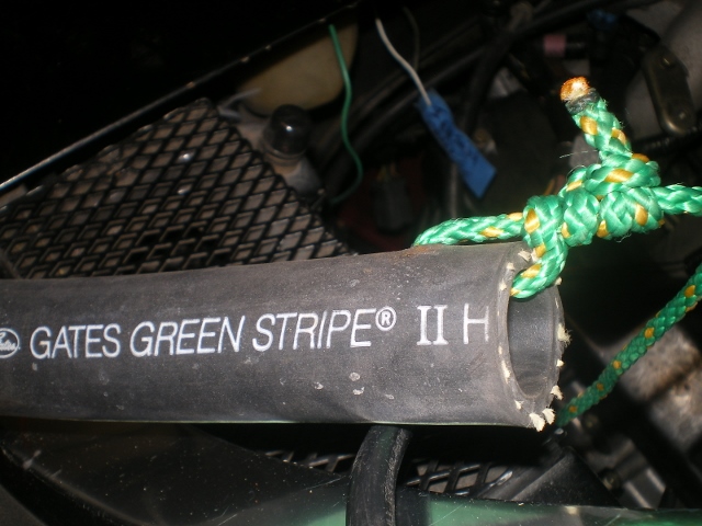 Using the curve in the hose I threaded it in engine side while pulling on the line until this. 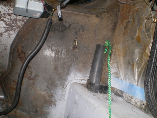 Then I threaded a 12" piece of the 2" vac hose back over the heater hose and thru the "90" to prevent the hose from kinking. The fit is so close that it enables me to make tighter turns. 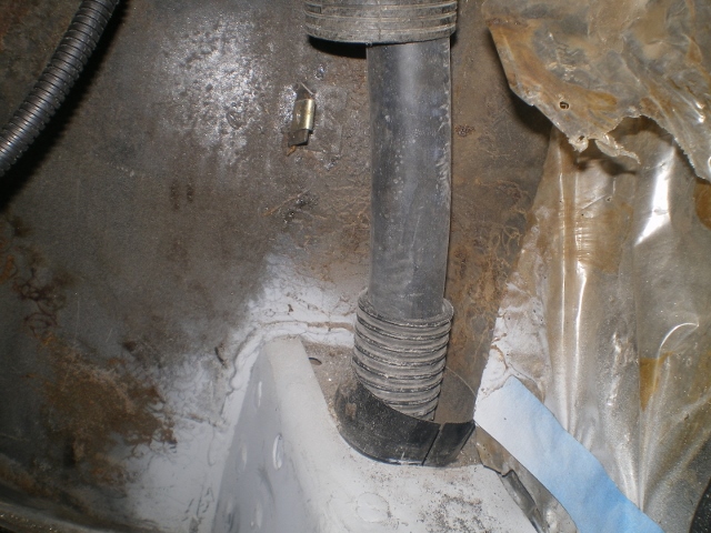 This is the larger and hotter of the 2 hoses so I'm running it in the pass long but I'm hoping that the way it's run will aid in not heating the long too much. I cut a piece of this 3" wet vac hose using the male end which fits very tightly inside the 90. I passed the other end thru the old hole into the area below the WWW reservoir. Inside this I added a piece of 2" so it is double walled. The greater pressure in the front compartment will pass somewhat thru the long and hopefully exhaust some heat. Here the 3" is slid over the heater hose and into the 90. 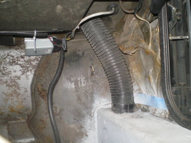 A shot of the tight fit I mentioned 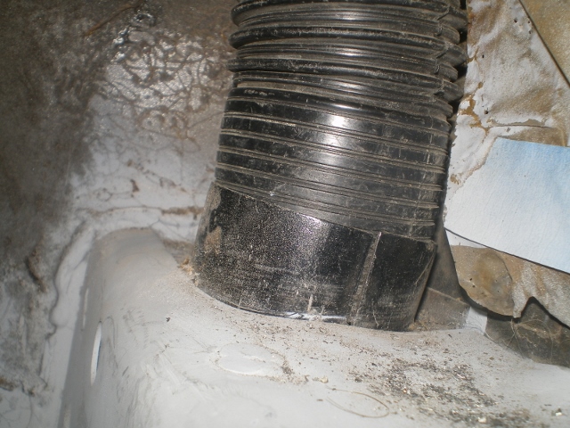 A look from the other side. 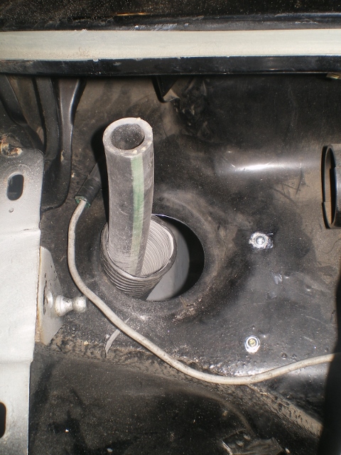 And the piece of 2" before it is placed inside the 3" to make it double walled. 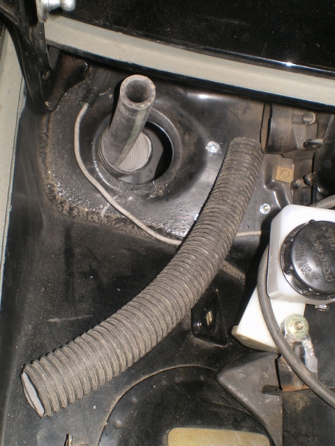 And with it threaded in. There will be another tight turn here and I want it for support as well. 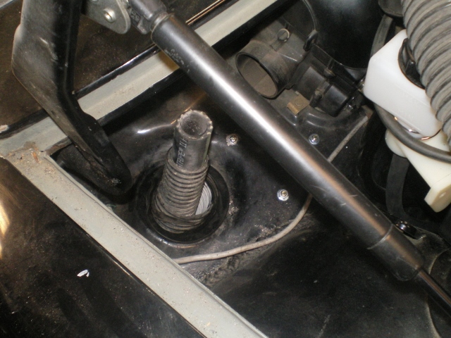 Now with the original grommet back in place. A good seal will be necessary if I want to exhaust some of that heat. 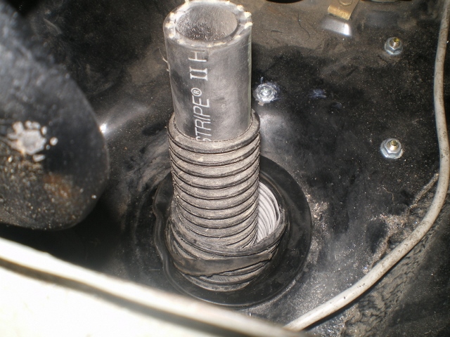 And with the reservoir back in place 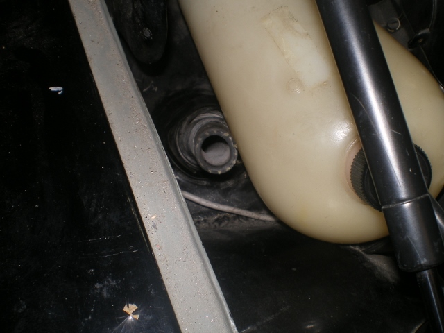 Real estate in this area is getting scarce. (IMG:style_emoticons/default/dry.gif) 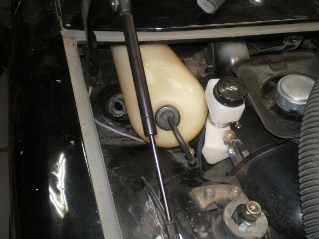 |
|
|
|
| Chris H. |
Feb 7 2014, 07:21 AM
Post
#233
|
|
Senior Member Group: Members Posts: 4,029 Joined: 2-January 03 From: Chicago 'burbs Member No.: 73 Region Association: Upper MidWest |
(IMG:style_emoticons/default/beerchug.gif) Alriiiiight!!! Now it's getting serious!
In continuation of the "bromance" you started I'm sending you some water wetter. Supposed to reduce temps a bit. I know Bob and others have confirmed it's pretty easy to cool a Subie but when you go through the longs you might get a little bump up. |
|
|
|
| CptTripps |
Feb 7 2014, 07:56 AM
Post
#234
|
|
:: Punch and Pie :: Group: Members Posts: 3,584 Joined: 26-December 04 From: Mentor, OH Member No.: 3,342 Region Association: Upper MidWest |
I was thinking of going through the longs as well. The idea I was going to try involved fire retardant "Great Stuff" foam injected into the longs after the hose was installed. I'm back/forth on it still.
There's also the idea of wrapping the tube with the stuff you use for headers and tailpipes. I bought a bunch of that to use at one time. Maybe it'll get put to good use here? Is there anyone that can tell me how hot the longs get without adding anything to help with the heat? |
|
|
|
| 76-914 |
Feb 7 2014, 09:57 AM
Post
#235
|
|
Repeat Offender & Resident Subaru Antagonist Group: Members Posts: 13,494 Joined: 23-January 09 From: Temecula, CA Member No.: 9,964 Region Association: Southern California |
QUOTE(Chris H. @ Feb 7 2014, 05:21 AM) (IMG:style_emoticons/default/beerchug.gif) Alriiiiight!!! Now it's getting serious! In continuation of the "bromance" you started I'm sending you some water wetter. Supposed to reduce temps a bit. I know Bob and others have confirmed it's pretty easy to cool a Subie but when you go through the longs you might get a little bump up. Thx Chris. That's super nice of you. I'm finished with the hydraulic clutch set up sans another AN3 90. Once that's in I'll finish up that portion of the post. Thanks for your help with the MC selection. QUOTE(CptTripps @ Feb 7 2014, 05:56 AM) I was thinking of going through the longs as well. The idea I was going to try involved fire retardant "Great Stuff" foam injected into the longs after the hose was installed. I'm back/forth on it still. There's also the idea of wrapping the tube with the stuff you use for headers and tailpipes. I bought a bunch of that to use at one time. Maybe it'll get put to good use here? Hey Doug, you might trap moisture using foam fillers and I don't think wrapping it will help with sliding it thru the long. I really don't expect any heat issues but I'm putting it on my wife's side. She's always complaining about the cold. (IMG:style_emoticons/default/happy11.gif) |
|
|
|
| Chris H. |
Feb 7 2014, 10:23 AM
Post
#236
|
|
Senior Member Group: Members Posts: 4,029 Joined: 2-January 03 From: Chicago 'burbs Member No.: 73 Region Association: Upper MidWest |
Yeah Doug the foam might be a bad idea...hate to see you get water trapped in that pretty car. If you fish the hoses through the heater tubes I'd think the heat transfer would be minimal but could be wrong...it's not touching the long directly for the most part right (IMG:style_emoticons/default/confused24.gif)
BTW I'll search the stash this weekend for door handles, thanx for the LED mirror turn signals! Bromance #2.... (IMG:style_emoticons/default/w00t.gif) |
|
|
|
| CptTripps |
Feb 7 2014, 11:15 AM
Post
#237
|
|
:: Punch and Pie :: Group: Members Posts: 3,584 Joined: 26-December 04 From: Mentor, OH Member No.: 3,342 Region Association: Upper MidWest |
I was more thinking about foaming the inside of the heater tube, once the radiator tube is installed. No real chance of water doing damage to a rubber tube, inside of another tube. I wouldn't want to fill up the long, unless I was 100% certain that I wasn't going to have any way for water to get in there. Most modern car frames are filled with foam without issue. (Although they weren't build with shitty seam welds in the 1970s.)
I'm at least a month away from needing to care about this, so I'll 'wait and see' what I can come up with between now and then. |
|
|
|
| JRust |
Feb 7 2014, 01:06 PM
Post
#238
|
|
914 Guru Group: Members Posts: 6,305 Joined: 10-January 03 From: Corvallis Oregon Member No.: 129 Region Association: Pacific Northwest |
I had mine run through the longs originally on my v8. It is damn near impossible to get all the air out of the system. The whole burping process is kind of a bitch. Much worse when you add an extra peak to the setup. If you are going to do it that way. I would do something to add a valve at the top by your gas tank on both sides. Not sure that will even get it all but it will sure help. You are also making your water pump work that much harder. Everyone hates them running under the car for some reason. I won't do it another way now. Although I have considered cutting the top off the center tunnel. Adding a good inch of height to the side. Then insulating & running them through the car. Also making the top of the tunnel a removable deal (IMG:style_emoticons/default/idea.gif)
As nice as you think it will be using the heater run in the longs. I can guarantee it will work better under your car. On my v8 I couldn't get it to cool consitently until I moved them under the car. Easy straight shot for running your hose & easier for your water pump to move all that water. Your already asking your water pump to push more water than it is designed for (IMG:style_emoticons/default/blink.gif) . With a Suby it may work just fine though. It isn't as much work to cool them as an old school v8. Can't wait to see how it comes out (IMG:style_emoticons/default/biggrin.gif) |
|
|
|
| skeates |
Feb 7 2014, 07:37 PM
Post
#239
|
|
Member Group: Members Posts: 218 Joined: 28-February 05 From: Sacramento, ca Member No.: 3,684 Region Association: Northern California |
I don't think the problem is that we are pumping "more" water than the pumps are designed for. The volume in the system does increase, but the gpm stays the same. Since it's an enclosed system there is no static head to speak of, so the pump won't notice the additional volume...sort of... We are in effect increasing the pumping head by adding more tubing length. Looking at some generic hose pressure drop chart you could be adding as much as 50 psi more head on the pump (assuming 10 feet of additional length, 3/4" hose, and 60 gpm)! More head = less flow at a given RPM = less ability to cool the motor. Interestingly, if you are running 1" hose for the same length and gpm the pressure drop is only 12 psi. Moral of the story here is to size your hose a bit bigger than stock (in my opinion).
I agree with Jamie that the way those hoses are currently routed will make bleeding the system a pain. I'm also wondering if that Gates hose can make that tight 90 degree bend at the front of the long without collapsing (pinching). I'm running the McMaster Carr variant hose and I know it would be pinching really bad with that tight of a radius. A pinch in the hose would mean certain cooling problems (massive flow reduction and likely flashing of the coolant inside the hose). I would double check that before committing - maybe the Gates hose can take tighter bends? |
|
|
|
| skeates |
Feb 7 2014, 07:45 PM
Post
#240
|
|
Member Group: Members Posts: 218 Joined: 28-February 05 From: Sacramento, ca Member No.: 3,684 Region Association: Northern California |
QUOTE(skeates @ Jan 20 2014, 07:37 PM) I guess I'm looking for the distance that the slave cylinder needs to travel in order to disengage the clutch. On mine I don't have a clutch or pressure plate yet so I can't make any measurements except to note that the clutch fork has easily 2" of travel (about 1 inch in either direction). Sounds like you will have a one to one rato on your system which will give you almost 1.5". I imagine that will be plenty. I'm just paranoid about getting the wrong size without doing the math. I don't know if it is useful at all, but I ended up answering my own question using my dad's Subaru outback. I had him push in the clutch while I measured the travel at the clutch fork and it only needed .5". Sheesh, that' nothing! So, it seems that any of the Wilwood clutch masters would work on the length of travel. It's really just a matter of picking how much mechanical advantage you want (smaller master = more mechanical advantage). |
|
|
|
|
1 User(s) are reading this topic (1 Guests and 0 Anonymous Users)
0 Members:

|
Lo-Fi Version | Time is now: 3rd May 2024 - 01:00 AM |
Invision Power Board
v9.1.4 © 2024 IPS, Inc.