|
|
|
Porsche, and the Porsche crest are registered trademarks of Dr. Ing. h.c. F. Porsche AG.
This site is not affiliated with Porsche in any way. Its only purpose is to provide an online forum for car enthusiasts. All other trademarks are property of their respective owners. |
|
|


| 76-914 |
 Jan 9 2013, 10:21 PM Jan 9 2013, 10:21 PM
Post
#741
|
|
Repeat Offender & Resident Subaru Antagonist  Group: Members Posts: 13,905 Joined: 23-January 09 From: Temecula, CA Member No.: 9,964 Region Association: Southern California |
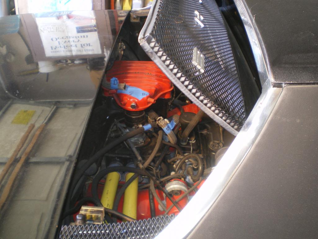
What's it been? A year since I got Blackie running. I finally get it tuned to a daily driver status and should have been happy as a Lark then but what do I do? I sold the engine (w/90 hour's on the Hobbs) on the last Dawn Patrol GMR run. So I pulled the engine and began preparing Blackie for her transformation.
 Before I go any further check out my Jack Stands. Min height 19.5", 12 ton and should hold up to a 6.7 quake or direct nuclear attack. 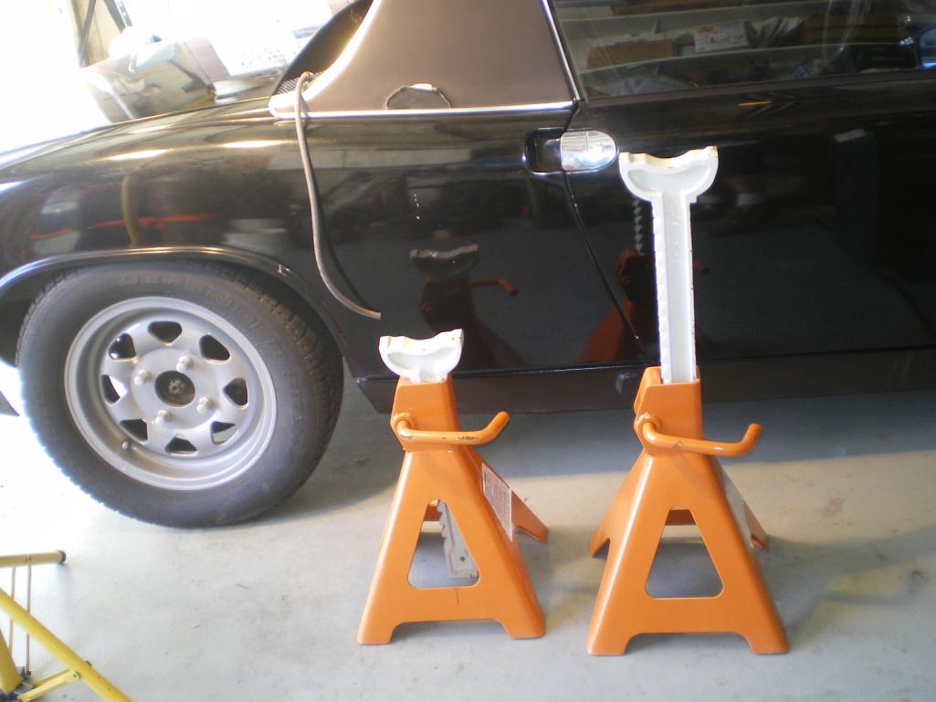 And out she comes. 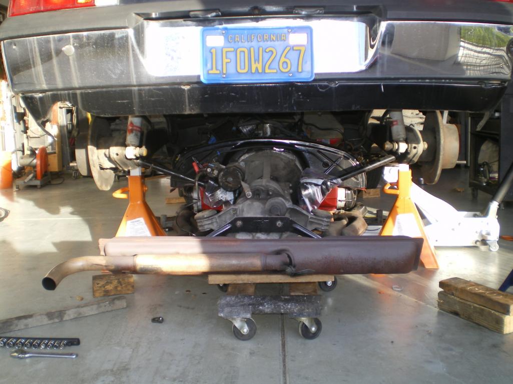 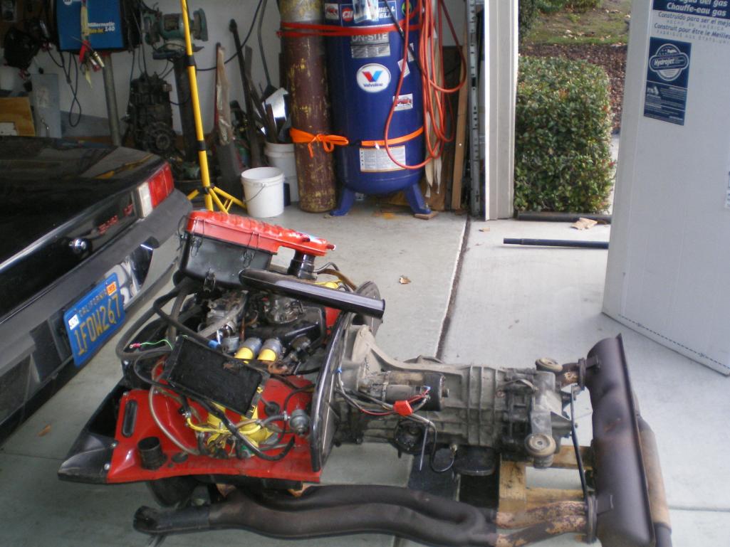 One thing you have to love about these cars is that you can remove an interior in 15 minutes. 30 min's if you have a console. This was one shot before the interior is gutted. 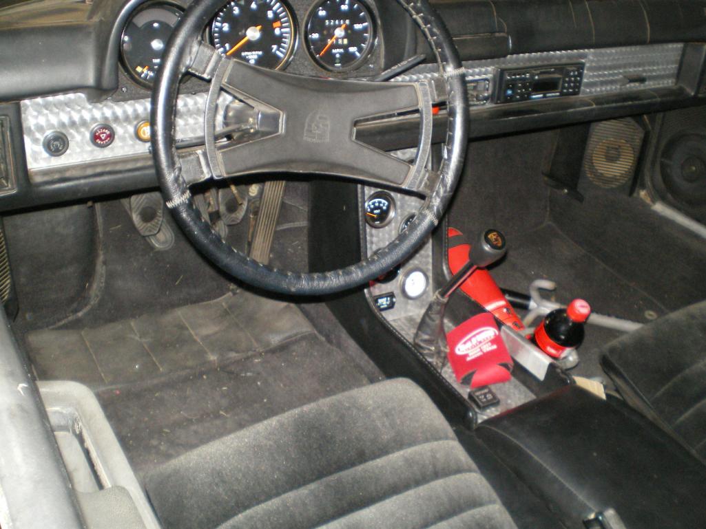 and an hour later I'm scraping tar floorboards. 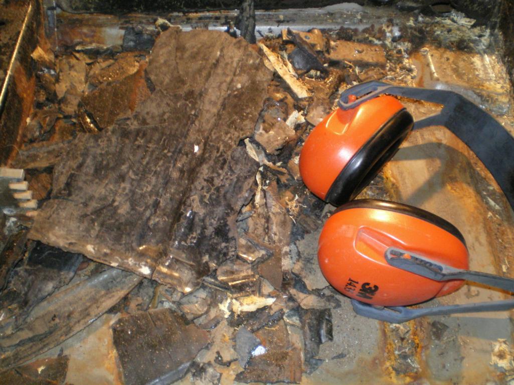 |
   |

 
|
Posts in this topic
 76-914 '73 Resto & Suby 6 Conversion Jan 9 2013, 10:21 PM
 76-914 So after a couple of hours this is what I found be... Jan 9 2013, 10:22 PM 76-914 So the pans look great but look what I found. I ha... Jan 9 2013, 10:33 PM '73-914kid Only 90 hours on the engine..? I think I have some... Jan 9 2013, 11:40 PM mrbubblehead Whats your plan Kent? Jan 9 2013, 11:57 PM 76-914 Plan? I knew I forgot something, :lol: The plan, q... Jan 10 2013, 10:13 AM 76-914 Before the fitting can happen I need to locate the... Jan 12 2013, 09:17 PM 76-914 So, weld areas are sanded, cleaned and hit with so... Jan 12 2013, 09:18 PM 76-914 There are places that need to be bent or formed an... Jan 12 2013, 09:38 PM
 Dasnowman
There are places that need to be bent or formed a... Jan 14 2013, 10:06 PM Cairo94507 Nice work and pictures. Keep 'em coming pleas... Jan 12 2013, 09:45 PM Chris H. Awesome. I need to do an Engman kit myself. You... Jan 14 2013, 07:44 AM 76-914
Awesome. I need to do an Engman kit myself. Yo... Jan 14 2013, 09:31 AM Chris H. Sure no prob. I have learned that no matter how c... Jan 14 2013, 11:29 AM 76-914 Thx Chris. Great info. I didn't know about the... Jan 14 2013, 12:32 PM Chris H. Yeah even if mine takes too long and costs too muc... Jan 14 2013, 01:33 PM Elliot Cannon You actually trust those jack stands?? :screwy: Jan 14 2013, 06:38 PM 76-914 Now that this Artic cold spell has passed I was ab... Jan 19 2013, 09:25 PM 76-914 A few shots of the rear stiffie after most of the ... Jan 19 2013, 09:26 PM Jeffs9146 OK this is the first time I have seen this thread ... Jan 19 2013, 09:35 PM 76-914
OK this is the first time I have seen this thread... Jan 20 2013, 11:40 AM 76-914 I got around to welding on the r&l long stiffn... Jan 20 2013, 10:05 PM 76-914 When I was banging around bracing the panels with ... Jan 20 2013, 10:06 PM FourBlades Nice work man! :Qarl:
John Jan 20 2013, 10:10 PM 76-914 Here is another view of the same corner but with t... Jan 20 2013, 10:23 PM 76-914 I finally finished the welding of the Engman kit. ... Jan 22 2013, 09:01 PM 76-914 and
Jan 24 2013, 10:13 PM jimkelly fantastic pics :headbanger:
do you plan to seam... Jan 25 2013, 03:52 AM 76-914 Thx Jim, and yes I have some Wurth's seam seal... Jan 25 2013, 01:24 PM 76-914 Just got off the phone after discussing metal shri... Jan 25 2013, 01:51 PM andys Here are my before and after dimensions. Red is af... Jan 25 2013, 02:04 PM 76-914 Similar results. Within .01" (.027mm) +/- of ... Jan 25 2013, 05:40 PM eric9144 :popcorn: This should make the Dawn Patrols more... Jan 25 2013, 06:01 PM Chris H. Top notch details on the Engman install. Thanks a... Jan 26 2013, 07:28 AM 76-914 So I started with the firewall patch/repair today.... Jan 26 2013, 07:01 PM 76-914 lfjuysblfc
Jan 26 2013, 07:01 PM stateofidleness *subscribed*
in the same boat. i'll take all ... Jan 27 2013, 12:33 AM 76-914 So while I wait for the "correct" size o... Feb 1 2013, 06:10 PM 76-914 %90 clean. A little more here and there then patch... Feb 1 2013, 06:10 PM 76-914 So I need to fill some holes where the batt tray w... Feb 3 2013, 06:15 PM 76-914 future Feb 3 2013, 06:15 PM 76-914 OK so here we go again. This is the area behind th... Feb 3 2013, 07:50 PM 76-914 Here we see it taking shape..
Now it is almost ... Feb 3 2013, 08:18 PM Socalandy Looking good Kent but who is this jester for? or w... Feb 3 2013, 08:46 PM 76-914 Hah, good one Andy! Just trying to hold it for... Feb 6 2013, 11:37 PM 76-914
and the pass side, not much to it
a litt... Feb 6 2013, 11:37 PM 76-914 Well, with the rust repair (I think) behind me it... Feb 7 2013, 04:59 PM 76-914 It's been too long so I'll post what I hav... Feb 24 2013, 07:58 PM 76-914 A few blanks Wurther'd into place
Another... Feb 24 2013, 08:18 PM 76-914 I'm going with a very good heater hose but not... Feb 24 2013, 08:30 PM 76-914 I'm glad this part is behind me. I had that th... Mar 3 2013, 07:36 PM Chris H. Man you are really moving fast! Great work... Mar 4 2013, 10:36 PM 76-914 Hey thanks, Chris. How's your's coming alo... Mar 9 2013, 11:05 AM 76-914 The top/cover piece slides beneath the rain channe... Mar 9 2013, 11:06 AM 76-914 Work has been keeping me busy so this is all that ... Mar 16 2013, 07:29 PM 76-914 Time to get the suspension upgraded. I've cove... Apr 8 2013, 09:23 PM JRust I would not recommend running your radiator lines ... Apr 8 2013, 10:18 PM 76-914 Hey Jamie, :poke: I thought of you last week whe... Apr 9 2013, 08:48 AM AZ914 Kent,
Maybe ping member 914GT.. he ran his lines f... Apr 9 2013, 09:40 AM Chris H. That was an excellent build! I'm bouncing... Apr 9 2013, 09:59 AM BIGKAT_83 Here's an idea for the under car hoses.
B... Apr 9 2013, 10:20 AM Chris H. Love it Bob. Really cool alternative. Apr 9 2013, 02:52 PM BIGKAT_83 This is a car from Canada that is posted on a pict... Apr 9 2013, 04:01 PM 76-914 Chris, I've done everything but chant. Maybe I... Apr 9 2013, 10:04 PM Chris H. 914GT attached the pipes in a pretty unique way...... Apr 10 2013, 06:27 AM 76-914 I haven't posted here for a few days and thoug... Apr 24 2013, 09:34 PM 76-914 Look what landed in my garage yesterday. Couldn... Apr 25 2013, 05:38 PM jsconst :Qarl: awesome, glad you found what you wanted. T... Apr 25 2013, 06:13 PM 76-914
:Qarl: awesome, glad you found what you wanted. ... Apr 26 2013, 07:40 AM jsconst
:Qarl: awesome, glad you found what you wanted.... Apr 26 2013, 08:09 AM Chris H. :cheer: :Qarl: :popcorn: :trophy: :trophy: :t... Apr 26 2013, 08:23 AM 76-914 Chris, I'd have to agree with you on the wirin... Jun 3 2013, 03:09 PM DBCooper You guys who re-purpose the wiring harness and all... Jun 3 2013, 04:00 PM Chris H. You're doing great Kent! I failed to mark... Jun 3 2013, 04:16 PM Jon H. I have an eg33 that will be going into my westfali... Jun 3 2013, 05:13 PM BIGKAT_83 Got a friend that is selling a 99k 2003 EZ30D with... Jun 3 2013, 05:34 PM ruby914 Cool!
This is the best part of the trip. :Qar... Jun 3 2013, 08:07 PM 76-914
You're doing great Kent! I failed to mar... Jun 3 2013, 08:59 PM 76-914
You're doing great Kent! I failed to mar... Jun 3 2013, 09:18 PM Jon H. Program the ECU? I didn't know I had to do th... Jun 4 2013, 04:41 AM DBCooper If you bought an aftermarket ECU from a company li... Jun 4 2013, 06:54 AM 76-914 Some very good points, DB. I had already formulate... Jun 15 2013, 08:57 AM Tilly74 Congrats on all the hard work! Will be watchi... Jun 15 2013, 09:47 AM 76-914 Well I finally got the last wiring harness out. If... Jun 17 2013, 08:48 AM bulitt Dear God. Jun 17 2013, 09:07 AM Chris H. Kent, I know that feeling but you are doing great.... Jun 17 2013, 09:18 AM ruby914 Piece of cake. :D
Learn how to open the connector... Jun 17 2013, 07:56 PM 76-914 Thanks guys, good info. And I hope that I pulled o... Jun 17 2013, 09:35 PM DBCooper What I thought was an intelligent way of organizin... Jun 18 2013, 05:48 AM 76-914 That's pretty much what I have planned except ... Jun 18 2013, 09:00 PM 76-914 Needed something to do but I have the engine clean... Jun 27 2013, 07:03 PM 76-914 The 4130 tube arrived so it was time to get Blacki... Jul 10 2013, 07:53 AM Chris H. Not sure about the 3.0 but the stock 3.3 manifolds... Jul 10 2013, 01:28 PM 76-914 Hey Chris :wavebye: , I thought about that so I w... Jul 11 2013, 09:58 AM Chris H.
Hey Chris :wavebye: , I thought about that so I ... Jul 11 2013, 05:25 PM 76-914
Hey Chris :wavebye: , I thought about that so I... Jul 11 2013, 07:44 PM 76-914 I received the trunk hinge from Restoration Design... Jul 11 2013, 10:22 AM mepstein Your "jack stands" scare me. Jul 11 2013, 08:18 PM 76-914 I ground out all the brazing from a previous repai... Jul 13 2013, 06:43 PM 76-914 Yippie :Qarl: Picked up a tranny from an 03 WRX ... Jul 20 2013, 09:38 PM
Dasnowman
There are places that need to be bent or formed a... Jan 14 2013, 10:06 PM Cairo94507 Nice work and pictures. Keep 'em coming pleas... Jan 12 2013, 09:45 PM Chris H. Awesome. I need to do an Engman kit myself. You... Jan 14 2013, 07:44 AM 76-914
Awesome. I need to do an Engman kit myself. Yo... Jan 14 2013, 09:31 AM Chris H. Sure no prob. I have learned that no matter how c... Jan 14 2013, 11:29 AM 76-914 Thx Chris. Great info. I didn't know about the... Jan 14 2013, 12:32 PM Chris H. Yeah even if mine takes too long and costs too muc... Jan 14 2013, 01:33 PM Elliot Cannon You actually trust those jack stands?? :screwy: Jan 14 2013, 06:38 PM 76-914 Now that this Artic cold spell has passed I was ab... Jan 19 2013, 09:25 PM 76-914 A few shots of the rear stiffie after most of the ... Jan 19 2013, 09:26 PM Jeffs9146 OK this is the first time I have seen this thread ... Jan 19 2013, 09:35 PM 76-914
OK this is the first time I have seen this thread... Jan 20 2013, 11:40 AM 76-914 I got around to welding on the r&l long stiffn... Jan 20 2013, 10:05 PM 76-914 When I was banging around bracing the panels with ... Jan 20 2013, 10:06 PM FourBlades Nice work man! :Qarl:
John Jan 20 2013, 10:10 PM 76-914 Here is another view of the same corner but with t... Jan 20 2013, 10:23 PM 76-914 I finally finished the welding of the Engman kit. ... Jan 22 2013, 09:01 PM 76-914 and
Jan 24 2013, 10:13 PM jimkelly fantastic pics :headbanger:
do you plan to seam... Jan 25 2013, 03:52 AM 76-914 Thx Jim, and yes I have some Wurth's seam seal... Jan 25 2013, 01:24 PM 76-914 Just got off the phone after discussing metal shri... Jan 25 2013, 01:51 PM andys Here are my before and after dimensions. Red is af... Jan 25 2013, 02:04 PM 76-914 Similar results. Within .01" (.027mm) +/- of ... Jan 25 2013, 05:40 PM eric9144 :popcorn: This should make the Dawn Patrols more... Jan 25 2013, 06:01 PM Chris H. Top notch details on the Engman install. Thanks a... Jan 26 2013, 07:28 AM 76-914 So I started with the firewall patch/repair today.... Jan 26 2013, 07:01 PM 76-914 lfjuysblfc
Jan 26 2013, 07:01 PM stateofidleness *subscribed*
in the same boat. i'll take all ... Jan 27 2013, 12:33 AM 76-914 So while I wait for the "correct" size o... Feb 1 2013, 06:10 PM 76-914 %90 clean. A little more here and there then patch... Feb 1 2013, 06:10 PM 76-914 So I need to fill some holes where the batt tray w... Feb 3 2013, 06:15 PM 76-914 future Feb 3 2013, 06:15 PM 76-914 OK so here we go again. This is the area behind th... Feb 3 2013, 07:50 PM 76-914 Here we see it taking shape..
Now it is almost ... Feb 3 2013, 08:18 PM Socalandy Looking good Kent but who is this jester for? or w... Feb 3 2013, 08:46 PM 76-914 Hah, good one Andy! Just trying to hold it for... Feb 6 2013, 11:37 PM 76-914
and the pass side, not much to it
a litt... Feb 6 2013, 11:37 PM 76-914 Well, with the rust repair (I think) behind me it... Feb 7 2013, 04:59 PM 76-914 It's been too long so I'll post what I hav... Feb 24 2013, 07:58 PM 76-914 A few blanks Wurther'd into place
Another... Feb 24 2013, 08:18 PM 76-914 I'm going with a very good heater hose but not... Feb 24 2013, 08:30 PM 76-914 I'm glad this part is behind me. I had that th... Mar 3 2013, 07:36 PM Chris H. Man you are really moving fast! Great work... Mar 4 2013, 10:36 PM 76-914 Hey thanks, Chris. How's your's coming alo... Mar 9 2013, 11:05 AM 76-914 The top/cover piece slides beneath the rain channe... Mar 9 2013, 11:06 AM 76-914 Work has been keeping me busy so this is all that ... Mar 16 2013, 07:29 PM 76-914 Time to get the suspension upgraded. I've cove... Apr 8 2013, 09:23 PM JRust I would not recommend running your radiator lines ... Apr 8 2013, 10:18 PM 76-914 Hey Jamie, :poke: I thought of you last week whe... Apr 9 2013, 08:48 AM AZ914 Kent,
Maybe ping member 914GT.. he ran his lines f... Apr 9 2013, 09:40 AM Chris H. That was an excellent build! I'm bouncing... Apr 9 2013, 09:59 AM BIGKAT_83 Here's an idea for the under car hoses.
B... Apr 9 2013, 10:20 AM Chris H. Love it Bob. Really cool alternative. Apr 9 2013, 02:52 PM BIGKAT_83 This is a car from Canada that is posted on a pict... Apr 9 2013, 04:01 PM 76-914 Chris, I've done everything but chant. Maybe I... Apr 9 2013, 10:04 PM Chris H. 914GT attached the pipes in a pretty unique way...... Apr 10 2013, 06:27 AM 76-914 I haven't posted here for a few days and thoug... Apr 24 2013, 09:34 PM 76-914 Look what landed in my garage yesterday. Couldn... Apr 25 2013, 05:38 PM jsconst :Qarl: awesome, glad you found what you wanted. T... Apr 25 2013, 06:13 PM 76-914
:Qarl: awesome, glad you found what you wanted. ... Apr 26 2013, 07:40 AM jsconst
:Qarl: awesome, glad you found what you wanted.... Apr 26 2013, 08:09 AM Chris H. :cheer: :Qarl: :popcorn: :trophy: :trophy: :t... Apr 26 2013, 08:23 AM 76-914 Chris, I'd have to agree with you on the wirin... Jun 3 2013, 03:09 PM DBCooper You guys who re-purpose the wiring harness and all... Jun 3 2013, 04:00 PM Chris H. You're doing great Kent! I failed to mark... Jun 3 2013, 04:16 PM Jon H. I have an eg33 that will be going into my westfali... Jun 3 2013, 05:13 PM BIGKAT_83 Got a friend that is selling a 99k 2003 EZ30D with... Jun 3 2013, 05:34 PM ruby914 Cool!
This is the best part of the trip. :Qar... Jun 3 2013, 08:07 PM 76-914
You're doing great Kent! I failed to mar... Jun 3 2013, 08:59 PM 76-914
You're doing great Kent! I failed to mar... Jun 3 2013, 09:18 PM Jon H. Program the ECU? I didn't know I had to do th... Jun 4 2013, 04:41 AM DBCooper If you bought an aftermarket ECU from a company li... Jun 4 2013, 06:54 AM 76-914 Some very good points, DB. I had already formulate... Jun 15 2013, 08:57 AM Tilly74 Congrats on all the hard work! Will be watchi... Jun 15 2013, 09:47 AM 76-914 Well I finally got the last wiring harness out. If... Jun 17 2013, 08:48 AM bulitt Dear God. Jun 17 2013, 09:07 AM Chris H. Kent, I know that feeling but you are doing great.... Jun 17 2013, 09:18 AM ruby914 Piece of cake. :D
Learn how to open the connector... Jun 17 2013, 07:56 PM 76-914 Thanks guys, good info. And I hope that I pulled o... Jun 17 2013, 09:35 PM DBCooper What I thought was an intelligent way of organizin... Jun 18 2013, 05:48 AM 76-914 That's pretty much what I have planned except ... Jun 18 2013, 09:00 PM 76-914 Needed something to do but I have the engine clean... Jun 27 2013, 07:03 PM 76-914 The 4130 tube arrived so it was time to get Blacki... Jul 10 2013, 07:53 AM Chris H. Not sure about the 3.0 but the stock 3.3 manifolds... Jul 10 2013, 01:28 PM 76-914 Hey Chris :wavebye: , I thought about that so I w... Jul 11 2013, 09:58 AM Chris H.
Hey Chris :wavebye: , I thought about that so I ... Jul 11 2013, 05:25 PM 76-914
Hey Chris :wavebye: , I thought about that so I... Jul 11 2013, 07:44 PM 76-914 I received the trunk hinge from Restoration Design... Jul 11 2013, 10:22 AM mepstein Your "jack stands" scare me. Jul 11 2013, 08:18 PM 76-914 I ground out all the brazing from a previous repai... Jul 13 2013, 06:43 PM 76-914 Yippie :Qarl: Picked up a tranny from an 03 WRX ... Jul 20 2013, 09:38 PM  |
2 User(s) are reading this topic (2 Guests and 0 Anonymous Users)
0 Members:

|
Lo-Fi Version | Time is now: 24th June 2026 - 04:09 PM |
Invision Power Board
v9.1.4 © 2026 IPS, Inc.