|
|
|
Porsche, and the Porsche crest are registered trademarks of Dr. Ing. h.c. F. Porsche AG.
This site is not affiliated with Porsche in any way. Its only purpose is to provide an online forum for car enthusiasts. All other trademarks are property of their respective owners. |
|
|


| andys |
 Feb 21 2013, 12:43 PM Feb 21 2013, 12:43 PM
Post
#41
|
|
Advanced Member  Group: Members Posts: 2,165 Joined: 21-May 03 From: Valencia, CA Member No.: 721 Region Association: None |
Here's the start of a retrospective build thread of my LS1 conversion. It took a few years to get it done mostly due to not wanting to be a slave to the project, and work on it for the enjoyment; and of course when family obligations allowed......teen daughter and high maintenance wife (IMG:style_emoticons/default/biggrin.gif)
What I started with was a local orignal owner '75 2.0 with 139K miles. The original owner "drove the heck out of it" until something died in the electrical system and he parked it in the garage for 14 years, as evidenced by the renewal tags. Only body damage was when he submarined the rear of a Mustang and creased the hood and flattened the left signal light pod. Otherwise, it was a good condition rust free (SoCal) car. Brief specs are: '01 LS1 Z28 motor, Audi 01E 6 speed tranaxle, 911 front suspension, custom made rear trailing arms, Koni shocks, 993 wheels, and AC. Below, are photos of what I started with, and what I ended-up with. I'll do my best to re-trace the build process, so if you have any questions along the way, please ask. BTW, how does one place text between photos in the same post? Andys Attached thumbnail(s) 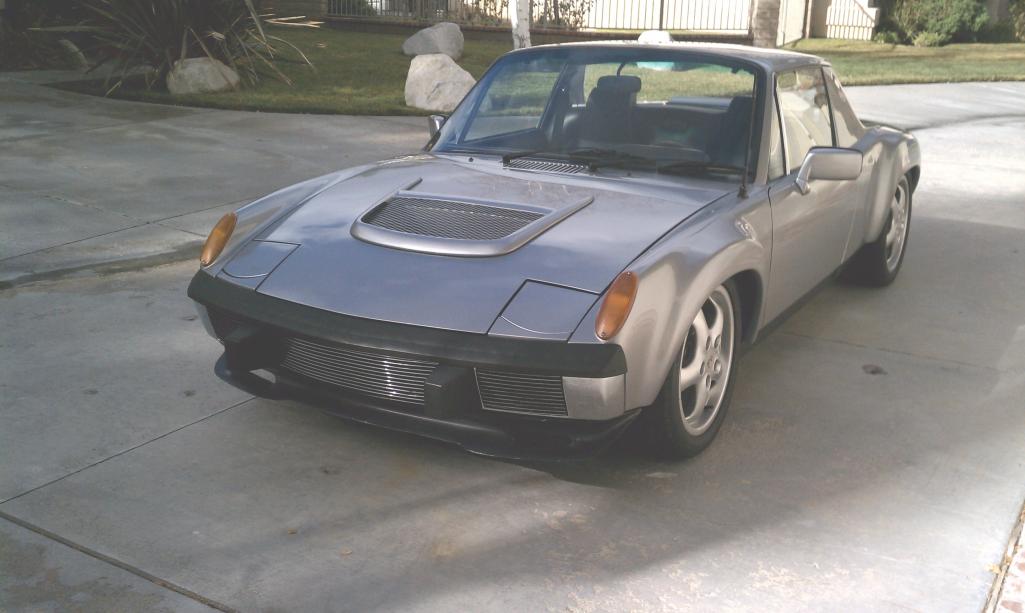 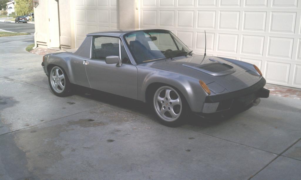  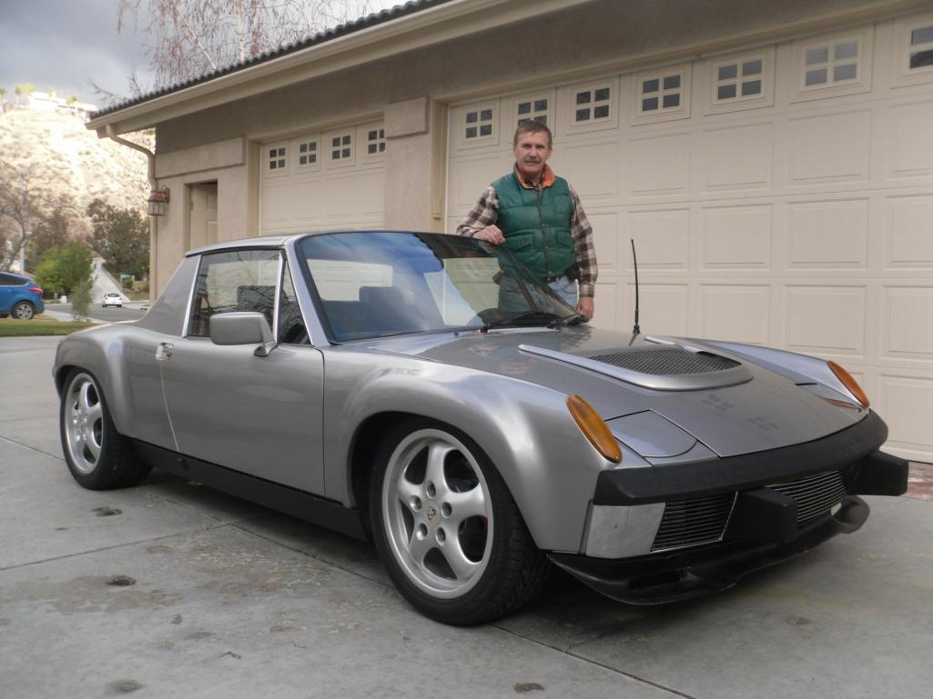 Attached image(s) 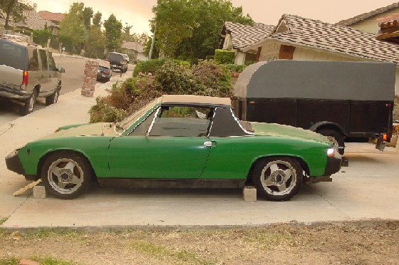 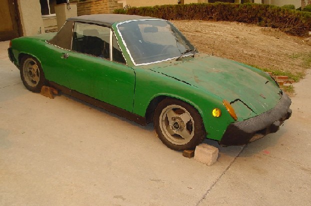 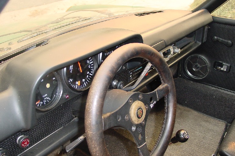
|
   |

 
|
Posts in this topic
 andys LS1 Conversion Feb 21 2013, 12:43 PM
 Tom_T In Full Edit mode - just add space lines with your... Feb 21 2013, 12:55 PM
 andys
In Full Edit mode - just add space lines with you... Feb 21 2013, 01:16 PM worn
In Full Edit mode - just add space lines with yo... Feb 21 2013, 02:07 PM andys I decided quite quickly, that I wanted to go with ... Feb 21 2013, 01:11 PM andys I wanted to avoid having a motor shipped, so I sta... Feb 21 2013, 02:34 PM andys I wanted to start by adapting the motor to the tra... Feb 21 2013, 05:48 PM Bruce Hinds Tell us about that jack! Feb 21 2013, 06:33 PM andys
Tell us about that jack!
Bruce,
I spend 6 ... Feb 21 2013, 06:47 PM turk22 Lovin this story and the work you did.
Looking fo... Feb 21 2013, 07:25 PM Bruce Hinds ask about the jack!
Well yeah... the cars fre... Feb 21 2013, 07:47 PM andys
ask about the jack!
Well yeah... the cars fr... Feb 22 2013, 10:27 AM kg6dxn Keep going! We need more!
I know you did ... Feb 21 2013, 07:47 PM andys With the motor and transaxle coupled together, I n... Feb 22 2013, 12:32 PM TurboWalt Great work, keep the pics coming! Feb 22 2013, 02:15 PM BIGKAT_83 Great work! keep the pictures coming. I keep c... Feb 22 2013, 02:29 PM andys While not exactly in the correct sequence of the b... Feb 22 2013, 03:07 PM worn Amazing. Inspiring. I wanna drive it! Feb 22 2013, 09:52 PM rick 918-S :beer2: :welder: :sawzall: :smash: :headbanger... Feb 23 2013, 07:39 AM Cairo94507 I am in awe. Amazing skills and work. Keep ... Feb 23 2013, 08:03 AM jersey914 Cool conversion, way out of my league Feb 23 2013, 08:54 AM Bruce Hinds Holy smokes, you're a handy guy to have around... Feb 24 2013, 10:16 AM andys I mentioned earlier the need to move the firewall ... Feb 24 2013, 12:01 PM messix have you left the tranny in the original location ... Feb 24 2013, 12:14 PM andys
have you left the tranny in the original location... Feb 24 2013, 12:16 PM messix
have you left the tranny in the original locatio... Feb 24 2013, 12:24 PM andys Determining where the engine/transaxle assembly wo... Feb 24 2013, 05:32 PM Krieger I like your work! Weight wise you better off w... Feb 24 2013, 07:16 PM andys The 01E transaxle flanges are a tripoid design whi... Feb 26 2013, 03:30 PM charliew great work. I also like the jack. I missed the par... Feb 26 2013, 05:26 PM andys
great work. I also like the jack. I missed the pa... Feb 26 2013, 06:34 PM andys So we've got the motor/transaxle mounted, and ... Feb 27 2013, 06:35 PM slothness :worship: Feb 27 2013, 06:40 PM trojanhorsepower wow........ that is impressive Feb 27 2013, 06:45 PM bigkensteele You, my friend, are insane! Incredible work... Feb 27 2013, 10:46 PM Bruce Hinds Holy mother of God! I thought the Jack was a ... Feb 27 2013, 11:08 PM andys Thanks for all the nice words!
A couple more ... Feb 28 2013, 12:04 PM get off my lawn What color is that jack, fire engine red?
j/k
... Feb 28 2013, 04:34 PM andys I re-enforced the inner suspension ears with a sor... Mar 4 2013, 02:33 PM JRust You really should have just made 2 of everything :... Mar 4 2013, 02:41 PM andys Let's install the Engman chassis stiffening ki... Mar 7 2013, 12:49 PM jd74914
I don't own a MIG welder, so TIG was my only ... Mar 7 2013, 06:40 PM andys
You need a thumb control Andy. They are perfect ... Mar 8 2013, 10:25 AM andys I forgot to mention, that I put a few Tek screws o... Mar 7 2013, 01:03 PM andys I installed fiberglass flares, and here's why.... Mar 12 2013, 02:07 PM andys As the cooling system is a crucial part of a V8 co... Mar 13 2013, 12:16 PM quadracerx WOW... Nice work!!
Has anyone tried a ... Mar 13 2013, 01:45 PM SouthCali914
WOW... Nice work!!
Has anyone tried a ... Mar 14 2013, 12:43 AM andys As promised, here's what I did with the radiat... Mar 14 2013, 01:47 PM andys I found a couple of more photos (with the exit duc... Mar 14 2013, 04:44 PM tscrihfield Andy, this has shown a lot of great, quality work... Mar 14 2013, 09:42 PM andys I stubled across a couple more coolant pipe photos... Mar 16 2013, 09:37 PM andys Here's how I did my shift linkage. I know that... Mar 20 2013, 12:26 PM andys Time to get back to posting more retrospective bui... Mar 26 2013, 02:08 PM andys Thought I'd go through the fuel system next. T... Mar 28 2013, 03:28 PM dflesburg Wow, amazing work, the only comment I have is why ... Mar 29 2013, 09:08 AM andys The AA steel flares were not yet available at the ... Mar 29 2013, 09:17 AM DBCooper Looks excellent, and like a whole lot of fun. I p... Mar 29 2013, 09:30 AM andys
Looks excellent, and like a whole lot of fun. I ... Mar 29 2013, 10:10 AM DBCooper I'm not worried about explaining anything to m... Mar 29 2013, 04:28 PM Rand But if you have that thing out somewhere and some ... Mar 29 2013, 10:42 AM dfelz Great build Andy, your work is top notch and looks... Mar 29 2013, 01:09 PM andys
Great build Andy, your work is top notch and look... Mar 29 2013, 01:41 PM dfelz Awesome, thanks! I love McMaster, they have ev... Mar 29 2013, 02:28 PM andys
Awesome, thanks! I love McMaster, they have e... Mar 29 2013, 02:49 PM dfelz
Awesome, thanks! I love McMaster, they have ... Mar 29 2013, 04:35 PM andys
[quote name='andys' post='1842361' date='Mar 29 2... Mar 30 2013, 08:40 PM dfelz
[quote name='andys' post='1842361' date='Mar 29 ... Mar 31 2013, 11:38 AM 914GT Andys
I've been following your build thread f... Mar 29 2013, 06:18 PM andys
Andys
I've been following your build thread ... Mar 30 2013, 08:59 PM kg6dxn I nominate this thread for the Classics.
It will ... Mar 31 2013, 11:58 AM BIGKAT_83 :agree:
Andy has set a new standard for everyone... Mar 31 2013, 12:33 PM andys I'm jumping around a bit, however lets go ahea... Apr 5 2013, 07:19 PM andys Thought I'd take y'all through the AC syst... Apr 11 2013, 12:20 PM drive-ability Andy,
That car looks fantastic ! My la... Oct 7 2013, 11:26 PM andys
Andy,
That car looks fantastic ! My l... Oct 8 2013, 01:45 PM 914forme Okay, I know your not to it in your story but I kn... Oct 8 2013, 06:35 PM 914forme double post- sorry Oct 8 2013, 06:35 PM andys
Okay, I know your not to it in your story but I k... Oct 9 2013, 10:10 AM 914forme Thank you sir that is absolutely brilliant, and I ... Oct 9 2013, 01:00 PM Mueller wow, just wow....great build...after seeing such i... Jan 18 2015, 11:54 AM drive-ability I want you on my team !!!!!... Jan 18 2015, 05:17 PM Maltese Falcon Just read through your thread with great enthusias... Jan 18 2015, 08:42 PM andys
Just read through your thread with great enthusia... Jan 19 2015, 10:41 AM Maltese Falcon
Just read through your thread with great enthusi... Jan 19 2015, 08:40 PM mgp4591 Thanks for the link Andy- got me inspired to work ... Jan 18 2015, 09:28 PM andys
Thanks for the link Andy- got me inspired to work... Jan 19 2015, 10:47 AM JRust
Thanks for the link Andy- got me inspired to wor... Jan 19 2015, 11:47 AM andys
[quote name='andys' post='2135997' date='Jan 19 2... Jan 19 2015, 12:17 PM JRust
Jamie,
Thanks for the heads-up. March is a maybe... Jan 19 2015, 04:22 PM Mueller Are you doing your own plating on the small steel ... Jan 19 2015, 04:39 PM andys
Are you doing your own plating on the small steel... Jan 20 2015, 11:04 AM Rand I just hope those who poopoo this conversion find ... Jan 19 2015, 09:57 PM drive-ability That is one nice car, great craftsmanship bumper ... Mar 26 2015, 11:18 PM Mueller Anything new to show us on this cool build? :) Aug 11 2017, 02:58 PM andys Well, the car is done, but then again, they are ne... Aug 11 2017, 03:38 PM whitetwinturbo :popcorn: :popcorn: :popcorn: .........lurking i... Aug 27 2017, 10:33 PM
andys
In Full Edit mode - just add space lines with you... Feb 21 2013, 01:16 PM worn
In Full Edit mode - just add space lines with yo... Feb 21 2013, 02:07 PM andys I decided quite quickly, that I wanted to go with ... Feb 21 2013, 01:11 PM andys I wanted to avoid having a motor shipped, so I sta... Feb 21 2013, 02:34 PM andys I wanted to start by adapting the motor to the tra... Feb 21 2013, 05:48 PM Bruce Hinds Tell us about that jack! Feb 21 2013, 06:33 PM andys
Tell us about that jack!
Bruce,
I spend 6 ... Feb 21 2013, 06:47 PM turk22 Lovin this story and the work you did.
Looking fo... Feb 21 2013, 07:25 PM Bruce Hinds ask about the jack!
Well yeah... the cars fre... Feb 21 2013, 07:47 PM andys
ask about the jack!
Well yeah... the cars fr... Feb 22 2013, 10:27 AM kg6dxn Keep going! We need more!
I know you did ... Feb 21 2013, 07:47 PM andys With the motor and transaxle coupled together, I n... Feb 22 2013, 12:32 PM TurboWalt Great work, keep the pics coming! Feb 22 2013, 02:15 PM BIGKAT_83 Great work! keep the pictures coming. I keep c... Feb 22 2013, 02:29 PM andys While not exactly in the correct sequence of the b... Feb 22 2013, 03:07 PM worn Amazing. Inspiring. I wanna drive it! Feb 22 2013, 09:52 PM rick 918-S :beer2: :welder: :sawzall: :smash: :headbanger... Feb 23 2013, 07:39 AM Cairo94507 I am in awe. Amazing skills and work. Keep ... Feb 23 2013, 08:03 AM jersey914 Cool conversion, way out of my league Feb 23 2013, 08:54 AM Bruce Hinds Holy smokes, you're a handy guy to have around... Feb 24 2013, 10:16 AM andys I mentioned earlier the need to move the firewall ... Feb 24 2013, 12:01 PM messix have you left the tranny in the original location ... Feb 24 2013, 12:14 PM andys
have you left the tranny in the original location... Feb 24 2013, 12:16 PM messix
have you left the tranny in the original locatio... Feb 24 2013, 12:24 PM andys Determining where the engine/transaxle assembly wo... Feb 24 2013, 05:32 PM Krieger I like your work! Weight wise you better off w... Feb 24 2013, 07:16 PM andys The 01E transaxle flanges are a tripoid design whi... Feb 26 2013, 03:30 PM charliew great work. I also like the jack. I missed the par... Feb 26 2013, 05:26 PM andys
great work. I also like the jack. I missed the pa... Feb 26 2013, 06:34 PM andys So we've got the motor/transaxle mounted, and ... Feb 27 2013, 06:35 PM slothness :worship: Feb 27 2013, 06:40 PM trojanhorsepower wow........ that is impressive Feb 27 2013, 06:45 PM bigkensteele You, my friend, are insane! Incredible work... Feb 27 2013, 10:46 PM Bruce Hinds Holy mother of God! I thought the Jack was a ... Feb 27 2013, 11:08 PM andys Thanks for all the nice words!
A couple more ... Feb 28 2013, 12:04 PM get off my lawn What color is that jack, fire engine red?
j/k
... Feb 28 2013, 04:34 PM andys I re-enforced the inner suspension ears with a sor... Mar 4 2013, 02:33 PM JRust You really should have just made 2 of everything :... Mar 4 2013, 02:41 PM andys Let's install the Engman chassis stiffening ki... Mar 7 2013, 12:49 PM jd74914
I don't own a MIG welder, so TIG was my only ... Mar 7 2013, 06:40 PM andys
You need a thumb control Andy. They are perfect ... Mar 8 2013, 10:25 AM andys I forgot to mention, that I put a few Tek screws o... Mar 7 2013, 01:03 PM andys I installed fiberglass flares, and here's why.... Mar 12 2013, 02:07 PM andys As the cooling system is a crucial part of a V8 co... Mar 13 2013, 12:16 PM quadracerx WOW... Nice work!!
Has anyone tried a ... Mar 13 2013, 01:45 PM SouthCali914
WOW... Nice work!!
Has anyone tried a ... Mar 14 2013, 12:43 AM andys As promised, here's what I did with the radiat... Mar 14 2013, 01:47 PM andys I found a couple of more photos (with the exit duc... Mar 14 2013, 04:44 PM tscrihfield Andy, this has shown a lot of great, quality work... Mar 14 2013, 09:42 PM andys I stubled across a couple more coolant pipe photos... Mar 16 2013, 09:37 PM andys Here's how I did my shift linkage. I know that... Mar 20 2013, 12:26 PM andys Time to get back to posting more retrospective bui... Mar 26 2013, 02:08 PM andys Thought I'd go through the fuel system next. T... Mar 28 2013, 03:28 PM dflesburg Wow, amazing work, the only comment I have is why ... Mar 29 2013, 09:08 AM andys The AA steel flares were not yet available at the ... Mar 29 2013, 09:17 AM DBCooper Looks excellent, and like a whole lot of fun. I p... Mar 29 2013, 09:30 AM andys
Looks excellent, and like a whole lot of fun. I ... Mar 29 2013, 10:10 AM DBCooper I'm not worried about explaining anything to m... Mar 29 2013, 04:28 PM Rand But if you have that thing out somewhere and some ... Mar 29 2013, 10:42 AM dfelz Great build Andy, your work is top notch and looks... Mar 29 2013, 01:09 PM andys
Great build Andy, your work is top notch and look... Mar 29 2013, 01:41 PM dfelz Awesome, thanks! I love McMaster, they have ev... Mar 29 2013, 02:28 PM andys
Awesome, thanks! I love McMaster, they have e... Mar 29 2013, 02:49 PM dfelz
Awesome, thanks! I love McMaster, they have ... Mar 29 2013, 04:35 PM andys
[quote name='andys' post='1842361' date='Mar 29 2... Mar 30 2013, 08:40 PM dfelz
[quote name='andys' post='1842361' date='Mar 29 ... Mar 31 2013, 11:38 AM 914GT Andys
I've been following your build thread f... Mar 29 2013, 06:18 PM andys
Andys
I've been following your build thread ... Mar 30 2013, 08:59 PM kg6dxn I nominate this thread for the Classics.
It will ... Mar 31 2013, 11:58 AM BIGKAT_83 :agree:
Andy has set a new standard for everyone... Mar 31 2013, 12:33 PM andys I'm jumping around a bit, however lets go ahea... Apr 5 2013, 07:19 PM andys Thought I'd take y'all through the AC syst... Apr 11 2013, 12:20 PM drive-ability Andy,
That car looks fantastic ! My la... Oct 7 2013, 11:26 PM andys
Andy,
That car looks fantastic ! My l... Oct 8 2013, 01:45 PM 914forme Okay, I know your not to it in your story but I kn... Oct 8 2013, 06:35 PM 914forme double post- sorry Oct 8 2013, 06:35 PM andys
Okay, I know your not to it in your story but I k... Oct 9 2013, 10:10 AM 914forme Thank you sir that is absolutely brilliant, and I ... Oct 9 2013, 01:00 PM Mueller wow, just wow....great build...after seeing such i... Jan 18 2015, 11:54 AM drive-ability I want you on my team !!!!!... Jan 18 2015, 05:17 PM Maltese Falcon Just read through your thread with great enthusias... Jan 18 2015, 08:42 PM andys
Just read through your thread with great enthusia... Jan 19 2015, 10:41 AM Maltese Falcon
Just read through your thread with great enthusi... Jan 19 2015, 08:40 PM mgp4591 Thanks for the link Andy- got me inspired to work ... Jan 18 2015, 09:28 PM andys
Thanks for the link Andy- got me inspired to work... Jan 19 2015, 10:47 AM JRust
Thanks for the link Andy- got me inspired to wor... Jan 19 2015, 11:47 AM andys
[quote name='andys' post='2135997' date='Jan 19 2... Jan 19 2015, 12:17 PM JRust
Jamie,
Thanks for the heads-up. March is a maybe... Jan 19 2015, 04:22 PM Mueller Are you doing your own plating on the small steel ... Jan 19 2015, 04:39 PM andys
Are you doing your own plating on the small steel... Jan 20 2015, 11:04 AM Rand I just hope those who poopoo this conversion find ... Jan 19 2015, 09:57 PM drive-ability That is one nice car, great craftsmanship bumper ... Mar 26 2015, 11:18 PM Mueller Anything new to show us on this cool build? :) Aug 11 2017, 02:58 PM andys Well, the car is done, but then again, they are ne... Aug 11 2017, 03:38 PM whitetwinturbo :popcorn: :popcorn: :popcorn: .........lurking i... Aug 27 2017, 10:33 PM  |
1 User(s) are reading this topic (1 Guests and 0 Anonymous Users)
0 Members:

|
Lo-Fi Version | Time is now: 16th June 2026 - 02:41 AM |
Invision Power Board
v9.1.4 © 2026 IPS, Inc.