|
|
|
Porsche, and the Porsche crest are registered trademarks of Dr. Ing. h.c. F. Porsche AG.
This site is not affiliated with Porsche in any way. Its only purpose is to provide an online forum for car enthusiasts. All other trademarks are property of their respective owners. |
|
|

  |

| ClayPerrine |
 Nov 18 2004, 09:02 AM Nov 18 2004, 09:02 AM
Post
#1
|
|
Life's been good to me so far.....  Group: Admin Posts: 16,545 Joined: 11-September 03 From: Hurst, TX. Member No.: 1,143 Region Association: NineFourteenerVille |
NOTE: DUE TO MY NOT LOOKING AT THE WIRING DIAGRAM BEFORE POSTING THIS, I HAVE EDITED IT TO REFLECT REALITY!! (IMG:style_emoticons/default/headbang.gif)
I noticed that there is a lot of questions out there relating to how the headlight motors work. So I put this together to see if I can clear it up. The headlight motor circuit functions like a 3 way light switch in your house. You all have seen them. The one you can turn on at the bottom of the stairs and turn off at the top. Well, when you turn on the headlights in a 914, you turn on the headlight motor. It's rotation turns off the headlight motor when the lights are up, using a set of wiper contacts in the motor. In the first diagram below, I outline the headlight circuit with the lights in the down position. Attached thumbnail(s) 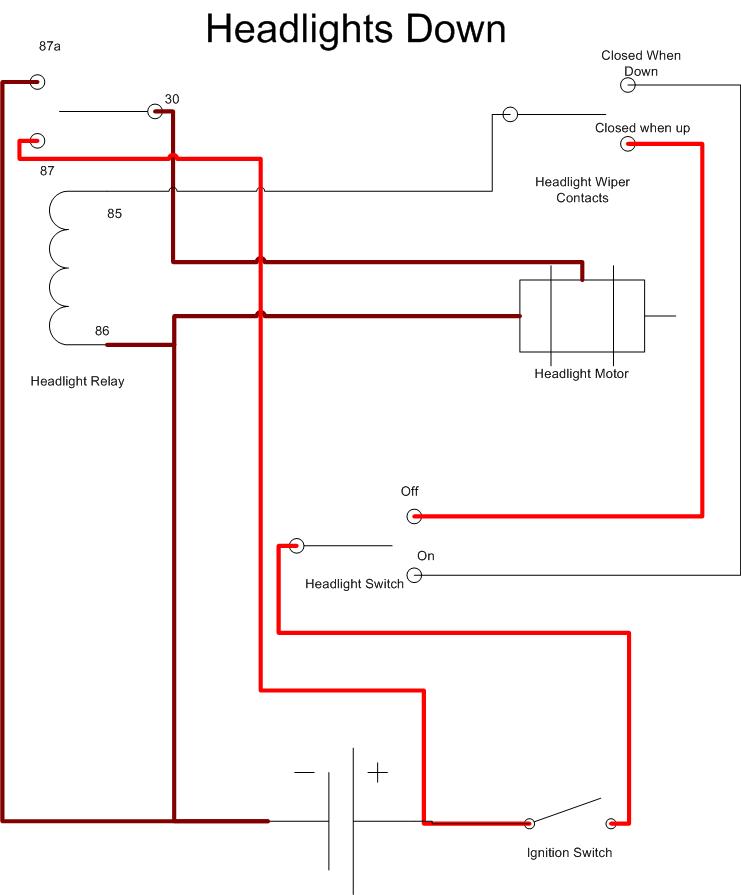
|
   |

 
|
| ClayPerrine |
Nov 18 2004, 09:10 AM
Post
#2
|
|
Life's been good to me so far..... Group: Admin Posts: 16,545 Joined: 11-September 03 From: Hurst, TX. Member No.: 1,143 Region Association: NineFourteenerVille |
In the next picture we see the headlight circuit while the motor is running to raise the headlights.
The headlight switch has connected to the on contact, supplying power to the "closed when down" wiper contact on the headlight motor. The common connection from the wiper contacts then supplies power to the relay to energize it. This connects pin 87 to pin 30 providing power to the headlight motor and starting it running. Attached thumbnail(s) 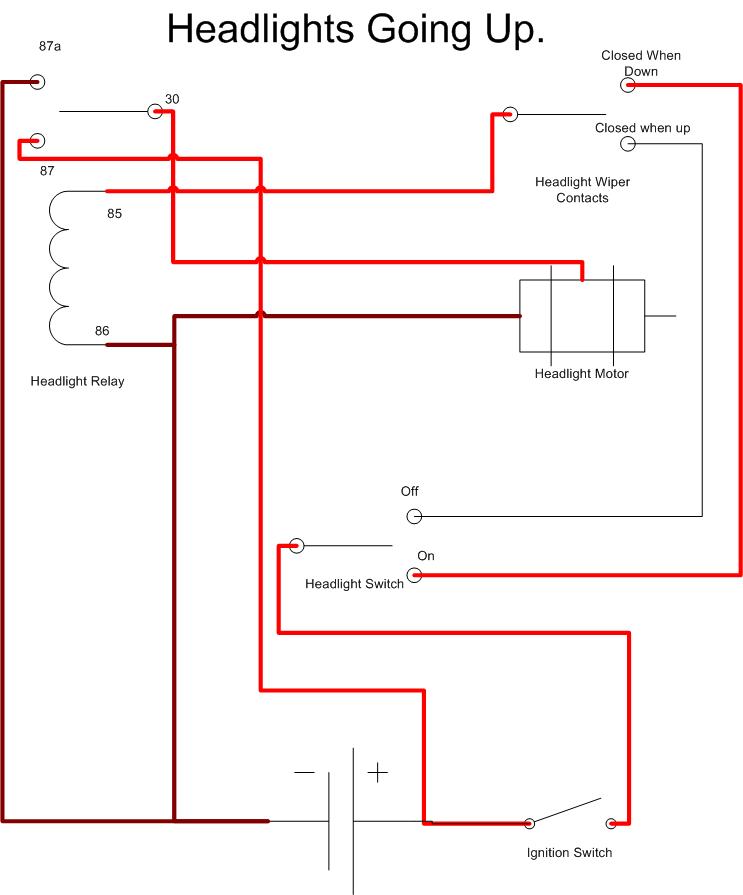
|
|
|
|
| Root_Werks |
Nov 18 2004, 09:11 AM
Post
#3
|
|
Village Idiot Group: Members Posts: 8,996 Joined: 25-May 04 From: About 15NM from Canada Member No.: 2,105 Region Association: Pacific Northwest |
Cool! (IMG:style_emoticons/default/smilie_pokal.gif)
|
|
|
|
| ClayPerrine |
Nov 18 2004, 09:13 AM
Post
#4
|
|
Life's been good to me so far..... Group: Admin Posts: 16,545 Joined: 11-September 03 From: Hurst, TX. Member No.: 1,143 Region Association: NineFourteenerVille |
When the headlights are all the way up, the wiper contacts in the motor change position, and the pin "Closed when headlight is up" is connected to the common contact. This removes power to the relay coil, and that breaks the circuit to the headlight motor, and the headlight stops moving.
Attached thumbnail(s) 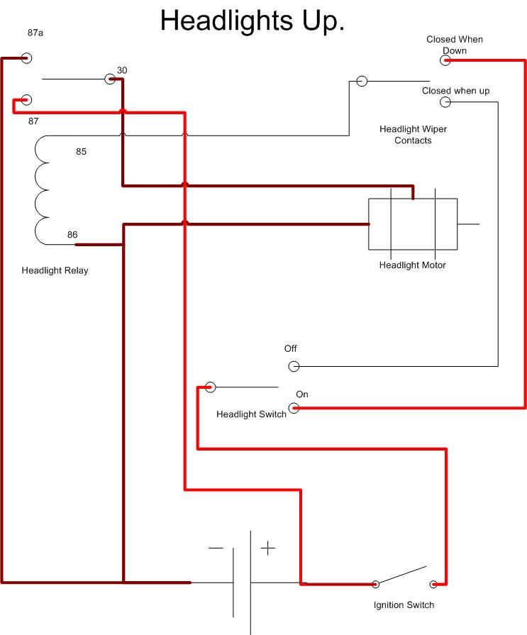
|
|
|
|
| ClayPerrine |
Nov 18 2004, 09:17 AM
Post
#5
|
|
Life's been good to me so far..... Group: Admin Posts: 16,545 Joined: 11-September 03 From: Hurst, TX. Member No.: 1,143 Region Association: NineFourteenerVille |
Now we turn the headlights off. The headlight switch connects power to the off contact, and that supplies power to the "closed when up" wiper contact, which then feeds power through the common contact to the relay coil. The relay energizes, connecting pin 87 to pin 30. That supplies power to the headlight motor to make it start moving down.
When the headlight reaches the down position, the wiper contacts connect the common pin to the "closed when down" connection, breaking the circuit to the relay coil, and that turns off the power to the motor. Attached thumbnail(s) 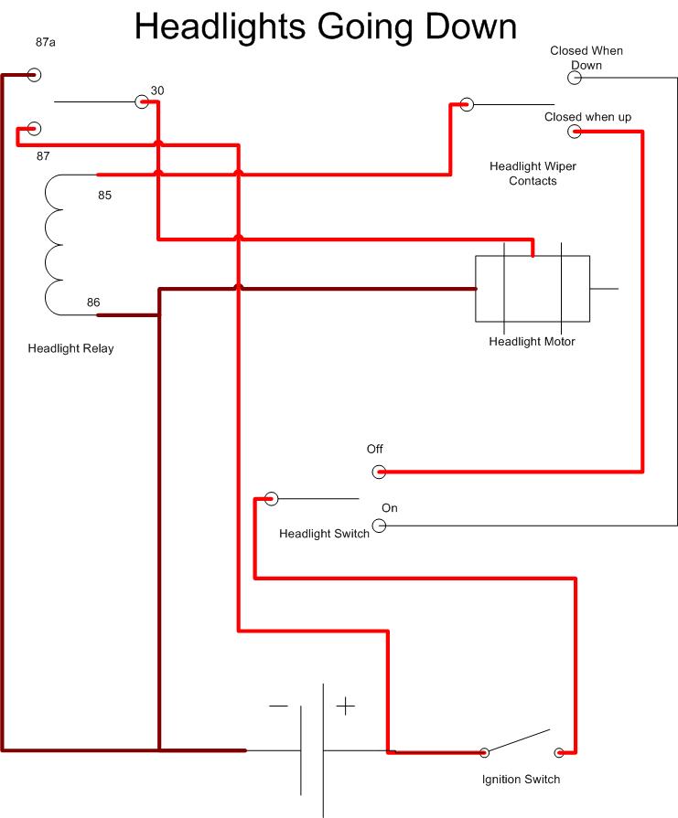
|
|
|
|
| ClayPerrine |
Nov 18 2004, 09:18 AM
Post
#6
|
|
Life's been good to me so far..... Group: Admin Posts: 16,545 Joined: 11-September 03 From: Hurst, TX. Member No.: 1,143 Region Association: NineFourteenerVille |
I hope that clears up the mystery of how the headlight motor circuit works.
|
|
|
|
| mikerose |
Nov 18 2004, 09:27 AM
Post
#7
|
|
Happy to be back Group: Members Posts: 657 Joined: 31-December 02 From: Pittsburg,ca Member No.: 60 Region Association: None |
(IMG:style_emoticons/default/clap56.gif) Thanks Clay (IMG:style_emoticons/default/clap56.gif)
|
|
|
|
| dralf |
Nov 18 2004, 09:34 AM
Post
#8
|
|
Member Group: Members Posts: 230 Joined: 24-January 04 From: Dayton, Oh Member No.: 1,597 |
(IMG:style_emoticons/default/clap56.gif)
Thanks, At the moment I am not having problems, but with a 914 it is just a matter of time and this is wonderful....I am printing it out and putting it in my note book. |
|
|
|
| ppickerell |
Nov 18 2004, 09:46 AM
Post
#9
|
|
914 addicted Group: Members Posts: 1,679 Joined: 14-October 03 From: Pleasanton, CA. Member No.: 1,246 |
Wow, you should try out for admin! (IMG:style_emoticons/default/wink.gif)
|
|
|
|
| jfort |
Nov 18 2004, 11:02 AM
Post
#10
|
|
Senior Member Group: Members Posts: 1,189 Joined: 5-May 03 From: Findlay, OH Member No.: 652 Region Association: Upper MidWest |
this needs to go in Classics or whatever it is -- the place for reference material. great job!
|
|
|
|
| ClayPerrine |
Nov 18 2004, 12:51 PM
Post
#11
|
|
Life's been good to me so far..... Group: Admin Posts: 16,545 Joined: 11-September 03 From: Hurst, TX. Member No.: 1,143 Region Association: NineFourteenerVille |
Bump... updated to reflect the reality of the wiring diagrams.
Sometimes it pays to look at the diagram FIRST! |
|
|
|
| Gint |
Nov 18 2004, 12:52 PM
Post
#12
|
|
Mike Ginter Group: Admin Posts: 16,108 Joined: 26-December 02 From: Denver CO. Member No.: 20 Region Association: Rocky Mountains |
Nice work Clay. Many thanks.
|
|
|
|
| chunger |
Nov 18 2004, 03:17 PM
Post
#13
|
|
Member Group: Members Posts: 409 Joined: 11-January 03 From: Albany, CA Member No.: 133 |
Sweet!
I was thinking about using an aftermarket harness (painless) for V8 car, but couldn't figure out how to do the popups. With this info, I can make the right circuit from scratch. -'Chung |
|
|
|
| Dave_Darling |
Nov 18 2004, 05:38 PM
Post
#14
|
|
914 Idiot Group: Members Posts: 15,342 Joined: 9-January 03 From: Silicon Valley / Kailua-Kona Member No.: 121 Region Association: Northern California |
...Is it just me, or are all three of those diagrams completely identical?
BTW, this definitely should go into the "classic" section--it's something that needs to be around for people to refer to in the future!!! --DD |
|
|
|
| swood |
Nov 18 2004, 07:05 PM
Post
#15
|
|
Senior Member Group: Members Posts: 1,845 Joined: 6-February 03 From: Strong Beach Member No.: 251 Region Association: None |
Great info! My lights go up and down and the high beams come on, but the low beams do not. (IMG:style_emoticons/default/confused24.gif)
|
|
|
|
| Dave_Darling |
Nov 18 2004, 07:10 PM
Post
#16
|
|
914 Idiot Group: Members Posts: 15,342 Joined: 9-January 03 From: Silicon Valley / Kailua-Kona Member No.: 121 Region Association: Northern California |
There is one fuse for each low beam element--two total. (Plus two more for the two high beams.) Check those.
I'd suspect the high/low beam relay, sitting up on top of the fuse panel. I believe that is the last place that both of the low beams share a common signal. Oh, if your lights are "stuck" on high beam, then I would also suspect the high/low switch in the turn signal switch assembly. --DD |
|
|
|
| type47fan |
Nov 18 2004, 07:29 PM
Post
#17
|
|
It Looks Better In Person. . . Group: Members Posts: 860 Joined: 17-September 03 From: Carlsbad, CA Member No.: 1,170 Region Association: Southern California |
Dave, it's just you! Check the differences in the relay terminals 30, 85, headlight switch, on/off etc. . . .
Wayne (type47fan) |
|
|
|
| 1973TwoLiter914 |
Apr 29 2020, 02:08 PM
Post
#18
|
|
Newbie Group: Members Posts: 2 Joined: 26-September 17 From: Cincinnati Member No.: 21,463 Region Association: Upper MidWest |
Clay - great visual ! I'm having issue with headlight synchronization and hoping your diagram and perhaps a reply could help me sort out the details...
- Both headlights Hi/Lo work, however it's a 1 Up and 1 Down situation - Left headlight operates perfectly in relation to the switch.....when switch is pulled out the headlight turns on and flips UP just fine. - Right headlight operates in the 'opposite' manner - meaning it is UP with the switch OFF and turns on and flips DOWN when the switch is pulled.......leading to a head scratcher. I've pulled the relay on the RIGHT light and tried to cycle thru with no result......wondering if the wires to the RT motor are somehow not lining up with the proper pins ??? Any help would be great ! |
|
|
|
| ClayPerrine |
Apr 30 2020, 12:15 AM
Post
#19
|
|
Life's been good to me so far..... Group: Admin Posts: 16,545 Joined: 11-September 03 From: Hurst, TX. Member No.: 1,143 Region Association: NineFourteenerVille |
QUOTE(1973TwoLiter914 @ Apr 29 2020, 03:08 PM)  Clay - great visual ! I'm having issue with headlight synchronization and hoping your diagram and perhaps a reply could help me sort out the details... - Both headlights Hi/Lo work, however it's a 1 Up and 1 Down situation - Left headlight operates perfectly in relation to the switch.....when switch is pulled out the headlight turns on and flips UP just fine. - Right headlight operates in the 'opposite' manner - meaning it is UP with the switch OFF and turns on and flips DOWN when the switch is pulled.......leading to a head scratcher. I've pulled the relay on the RIGHT light and tried to cycle thru with no result......wondering if the wires to the RT motor are somehow not lining up with the proper pins ??? Any help would be great ! There is a connector near the headlight motor with 3 wires in it that hooks the motor to the wire harness. Check it on the side that is working backwards, and verify the wire colors match from one side of the connector to the other. Clay |
|
|
|
| partwerks |
Sep 30 2021, 06:46 PM
Post
#20
|
|
Senior Member Group: Members Posts: 1,621 Joined: 7-September 06 From: Grand Island, NE Member No.: 6,787 |
QUOTE(ClayPerrine @ Apr 29 2020, 10:15 PM) QUOTE(1973TwoLiter914 @ Apr 29 2020, 03:08 PM) Clay - great visual ! I'm having issue with headlight synchronization and hoping your diagram and perhaps a reply could help me sort out the details... - Both headlights Hi/Lo work, however it's a 1 Up and 1 Down situation - Left headlight operates perfectly in relation to the switch.....when switch is pulled out the headlight turns on and flips UP just fine. - Right headlight operates in the 'opposite' manner - meaning it is UP with the switch OFF and turns on and flips DOWN when the switch is pulled.......leading to a head scratcher. I've pulled the relay on the RIGHT light and tried to cycle thru with no result......wondering if the wires to the RT motor are somehow not lining up with the proper pins ??? Any help would be great ! There is a connector near the headlight motor with 3 wires in it that hooks the motor to the wire harness. Check it on the side that is working backwards, and verify the wire colors match from one side of the connector to the other. Clay In the last paragraph. Is that something that could have accidentally been changed on both sides, that would make my lights go down when the switch is pulled out? Picture of it would be nice. Also, is there a diagram of the wires that go to the headlight switch, and colors. It's on a 1975. |
|
|
|
|
1 User(s) are reading this topic (1 Guests and 0 Anonymous Users)
0 Members:

|
Lo-Fi Version | Time is now: 8th June 2026 - 11:56 PM |
Invision Power Board
v9.1.4 © 2026 IPS, Inc.