|
|
|
Porsche, and the Porsche crest are registered trademarks of Dr. Ing. h.c. F. Porsche AG.
This site is not affiliated with Porsche in any way. Its only purpose is to provide an online forum for car enthusiasts. All other trademarks are property of their respective owners. |
|
|


| Curbandgutter |
 Mar 25 2013, 01:12 PM Mar 25 2013, 01:12 PM
Post
#81
|
|
Senior Member  Group: Members Posts: 566 Joined: 8-March 13 From: Murrieta CA Member No.: 15,637 Region Association: Southern California |
Well the dream begins. I'm embarking on the building of a 914 project. Here is the candidate. Bought a roller from LA area. Looks like its not going to be too much rust. Firsts thing will be to strip it. Taking front fenders and rear quarters off. Then sending to Cal Blast for media blasting. I look forward to the knowledge that I can gain from fellow enthusiasts. Plan on taking a lot of pics Stay tuned......
DISCLAIMER: Do not attempt to duplicate anything that is mentioned or illustrated in the entirety of this thread. I do not make any warranties of any kind. If you try to build what I am doing, you take full risk. Do not try this. It may be dangerous to your health and may get you killed 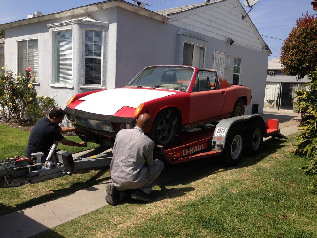 |
   |

 
|
Posts in this topic
 Curbandgutter 914RS4 Tube Chassis 996 Suspension Audi 2.7TT Stage 3 Mar 25 2013, 01:12 PM
 kg6dxn :wttc: Mar 25 2013, 07:07 PM BMiller Welcome aboard! :beer2: Mar 25 2013, 08:00 PM pcar916 :beer2:
Good luck! :wttc: Mar 25 2013, 08:26 PM KaptKaos Cool!! Where are you in SoCal? Mar 25 2013, 09:14 PM Elliot Cannon Come to the G&R swap meet. Lots of stuff ther... Mar 25 2013, 10:15 PM
kg6dxn :wttc: Mar 25 2013, 07:07 PM BMiller Welcome aboard! :beer2: Mar 25 2013, 08:00 PM pcar916 :beer2:
Good luck! :wttc: Mar 25 2013, 08:26 PM KaptKaos Cool!! Where are you in SoCal? Mar 25 2013, 09:14 PM Elliot Cannon Come to the G&R swap meet. Lots of stuff ther... Mar 25 2013, 10:15 PM rpmmaxxed
Come to the G&R swap meet. Lots of stuff the... Mar 26 2013, 02:02 AM
rpmmaxxed
Come to the G&R swap meet. Lots of stuff the... Mar 26 2013, 02:02 AM Curbandgutter
Come to the G&R swap meet. Lots of stuff the... Mar 26 2013, 12:23 PM carr914 :wttc:
and Elliot, wasn't there a Cage in Zo... Mar 26 2013, 05:25 AM Elliot Cannon
:wttc:
and Elliot, wasn't there a Cage in Z... Apr 12 2013, 11:48 AM monkeyboy Generally cages are unsafe in street cars because ... Mar 26 2013, 08:39 AM Curbandgutter
Generally cages are unsafe in street cars because... Mar 26 2013, 12:19 PM andys Ok, you got my attention.......which twin cam V8? ... Mar 26 2013, 09:48 AM Curbandgutter
Ok, you got my attention.......which twin cam V8?... Mar 26 2013, 12:14 PM carr914
Generally cages are unsafe in street cars because... Mar 26 2013, 12:19 PM rpmmaxxed
Generally cages are unsafe in street cars becaus... Mar 26 2013, 12:34 PM Joe Sharp The party thread.
http://www.914world.com/bbs2/in... Mar 26 2013, 05:27 PM Curbandgutter
The party thread.
http://www.914world.com/bbs2/i... Mar 27 2013, 10:20 AM Curbandgutter I have most of the car stripped. Making a rotisse... Apr 12 2013, 11:14 AM Elliot Cannon
I have most of the car stripped. Making a rotiss... Apr 12 2013, 11:53 AM Curbandgutter I can personally recommend the Sheridan body.
... Apr 12 2013, 03:29 PM Curbandgutter Well here are some more pictures of the progress. ... Apr 15 2013, 02:51 PM bulitt
Well here are some more pictures of the progress.... Apr 15 2013, 03:06 PM Curbandgutter More pics Apr 15 2013, 02:52 PM Curbandgutter Bundle of wires Apr 15 2013, 03:01 PM BMiller Good job so far. Keep it up! :beer2: Apr 15 2013, 09:05 PM Jgilliam914 Take good care of that Harness! Your gonna nee... Apr 16 2013, 01:00 PM Curbandgutter Thank you for the suggestion. Also with respect t... Apr 16 2013, 02:22 PM Curbandgutter I'm also planning on removing the center tunne... Apr 16 2013, 02:38 PM effutuo101 keep it up! a lot of work ahead, but it will b... Apr 18 2013, 03:35 PM Curbandgutter Well it has been a while but I have been collectin... Aug 4 2014, 01:13 PM Elliot Cannon
Well it has been a while but I have been collecti... Aug 4 2014, 02:10 PM ThePaintedMan
We're gonna have to see some pictures. If we... Aug 4 2014, 06:43 PM BIGKAT_83
Well it has been a while but I have been collecti... Aug 5 2014, 08:01 AM Curbandgutter
Well it has been a while but I have been collect... Aug 5 2014, 11:50 AM Justinp71 Sounds like a good project... funny, one just sold... Aug 4 2014, 01:31 PM Curbandgutter
Sounds like a good project... funny, one just sol... Aug 4 2014, 04:44 PM Curbandgutter damm iphone will not hook up to my computer. I... Aug 4 2014, 04:11 PM 76-914 You need that harness up to the 14pin connector at... Aug 4 2014, 06:23 PM Curbandgutter George, Thank you....I know what you mean. Hopefu... Aug 4 2014, 06:47 PM Curbandgutter OK here are some pictures. Aug 4 2014, 06:51 PM Curbandgutter It's been a while......life happens. I'm ... Jun 7 2016, 07:15 PM rick 918-S How'd I miss this? Belated :wttc: Jun 7 2016, 08:44 PM Curbandgutter
How'd I miss this? Belated :wttc:
Thanks. Jun 16 2016, 06:23 PM arkitect Can't wait to see more.
Dave Jun 8 2016, 06:21 AM Curbandgutter Well here is the rotisserie that I made. I took t... Jun 14 2016, 02:29 PM 76-914 Looking forward to this. Damn nice rotisserie. Joh... Jun 16 2016, 06:55 PM Curbandgutter
Looking forward to this. Damn nice rotisserie. Jo... Jun 17 2016, 09:15 AM Curbandgutter Well since I have to wait until my sand blast kit ... Jun 17 2016, 09:46 AM 87m491 Wow, a ton of adjustment (and adjusters!) on t... Jun 17 2016, 09:52 AM 2mAn Im not sure which body kit you are looking for but... Jun 17 2016, 10:14 AM Curbandgutter
Im not sure which body kit you are looking for bu... Jun 17 2016, 10:35 AM 2mAn
I've really thought it through and finally ca... Jun 17 2016, 10:57 AM Curbandgutter
I've really thought it through and finally c... Jun 17 2016, 11:18 AM Andyrew
[quote name='2mAn' post='2360624' date='Jun 17 20... Jun 17 2016, 03:14 PM Mueller Neat project.
For mounting the suspension, what a... Jun 17 2016, 10:34 AM Curbandgutter
Neat project.
For mounting the suspension, what ... Jun 17 2016, 10:42 AM 76-914 Damn Bubba, your in my backyard. PM me your addres... Jun 17 2016, 02:05 PM Curbandgutter
Damn Bubba, your in my backyard. PM me your addre... Jun 17 2016, 02:35 PM Curbandgutter And here is the front suspension. I'll be pow... Jun 17 2016, 07:56 PM Curbandgutter Here is the mock up of the rear suspension along w... Jun 18 2016, 06:07 PM Andyrew Looks sweet! Lots of work, but that kind of wo... Jun 18 2016, 07:38 PM Curbandgutter
Looks sweet! Lots of work, but that kind of w... Jun 19 2016, 09:20 PM r_towle Challenging exhaust..... Jun 18 2016, 10:12 PM Curbandgutter
Challenging exhaust.....
It used to be challeng... Jun 19 2016, 09:24 PM Mueller
Challenging exhaust.....
It used to be challen... Jun 19 2016, 09:52 PM Curbandgutter
[quote name='Curbandgutter' post='2361479' date='... Jun 19 2016, 11:02 PM Curbandgutter Little teaser as to what the frame will look like. Jun 19 2016, 11:02 PM Andyrew
Little teaser as to what the frame will look like... Jun 19 2016, 11:15 PM Curbandgutter
Little teaser as to what the frame will look lik... Jun 20 2016, 10:22 AM Randal
Little teaser as to what the frame will look like... Jun 21 2016, 11:17 AM Mark Garriott
Little teaser as to what the frame will look lik... Jun 21 2016, 01:13 PM Curbandgutter
Little teaser as to what the frame will look lik... Jun 21 2016, 03:14 PM Randal
[quote name='Randal' post='2362089' date='Jun 21 ... Jun 21 2016, 03:41 PM 76-914 I went to Rudy's Saturday to check out his pro... Jun 21 2016, 09:08 AM Mueller
I went to Rudy's Saturday to check out his pr... Jun 21 2016, 09:25 AM Curbandgutter
I went to Rudy's Saturday to check out his p... Jun 21 2016, 03:16 PM Curbandgutter
I went to Rudy's Saturday to check out his pr... Jun 21 2016, 03:18 PM 914forme :confused: The top of that rollbar must be 2... Jun 21 2016, 12:21 PM Curbandgutter Well I started to analyze the frame and found that... Jun 21 2016, 03:43 PM Chris914n6
http://www.914world.com/bbs2/uploads/post-15637-1... Jun 27 2016, 08:54 PM jd74914 Sweet! You don't see too many people doing... Jun 21 2016, 11:40 PM Curbandgutter
Sweet! You don't see too many people doin... Jun 22 2016, 09:44 AM jd74914
Now that's what I'm talking about! ... Jun 22 2016, 09:58 PM Mueller Are you going to model the suspension?
If so chec... Jun 22 2016, 02:07 PM Curbandgutter
Are you going to model the suspension?
If so che... Jun 22 2016, 03:18 PM 914forme
The next item on the list is to build the frame... Jun 22 2016, 03:33 PM Curbandgutter I am making it out of 4x4 tubing. The tubing has ... Jun 22 2016, 05:35 PM Curbandgutter
I am making it out of 4x4 tubing. The tubing has... Jun 22 2016, 06:02 PM Curbandgutter Thank You JD. I appreciate your excellent input. Jun 23 2016, 10:30 AM Curbandgutter 2g Lateral Load at rear yields a 1/16" latera... Jun 23 2016, 08:01 PM jd74914
2g Lateral Load at rear yields a 1/16" later... Jun 23 2016, 10:08 PM Curbandgutter I'm feeling pretty good about this chassis :ch... Jun 23 2016, 08:05 PM Curbandgutter That did it. Since the lower frame is flush with ... Jun 24 2016, 11:52 AM jd74914
That did it. Since the lower frame is flush with... Jun 27 2016, 09:09 AM Curbandgutter It uses thick tubing for the main hoops and thinne... Jun 27 2016, 04:51 PM Curbandgutter Well the material came in for the the chassis tabl... Jun 27 2016, 04:56 PM 76-914 Hey Rudy, I almost stopped by today but then I tho... Jun 27 2016, 06:12 PM Curbandgutter No more connections. We used to be in the industr... Jun 27 2016, 06:35 PM jd74914
It uses thick tubing for the main hoops and thinn... Jun 27 2016, 07:00 PM
Curbandgutter
Come to the G&R swap meet. Lots of stuff the... Mar 26 2013, 12:23 PM carr914 :wttc:
and Elliot, wasn't there a Cage in Zo... Mar 26 2013, 05:25 AM Elliot Cannon
:wttc:
and Elliot, wasn't there a Cage in Z... Apr 12 2013, 11:48 AM monkeyboy Generally cages are unsafe in street cars because ... Mar 26 2013, 08:39 AM Curbandgutter
Generally cages are unsafe in street cars because... Mar 26 2013, 12:19 PM andys Ok, you got my attention.......which twin cam V8? ... Mar 26 2013, 09:48 AM Curbandgutter
Ok, you got my attention.......which twin cam V8?... Mar 26 2013, 12:14 PM carr914
Generally cages are unsafe in street cars because... Mar 26 2013, 12:19 PM rpmmaxxed
Generally cages are unsafe in street cars becaus... Mar 26 2013, 12:34 PM Joe Sharp The party thread.
http://www.914world.com/bbs2/in... Mar 26 2013, 05:27 PM Curbandgutter
The party thread.
http://www.914world.com/bbs2/i... Mar 27 2013, 10:20 AM Curbandgutter I have most of the car stripped. Making a rotisse... Apr 12 2013, 11:14 AM Elliot Cannon
I have most of the car stripped. Making a rotiss... Apr 12 2013, 11:53 AM Curbandgutter I can personally recommend the Sheridan body.
... Apr 12 2013, 03:29 PM Curbandgutter Well here are some more pictures of the progress. ... Apr 15 2013, 02:51 PM bulitt
Well here are some more pictures of the progress.... Apr 15 2013, 03:06 PM Curbandgutter More pics Apr 15 2013, 02:52 PM Curbandgutter Bundle of wires Apr 15 2013, 03:01 PM BMiller Good job so far. Keep it up! :beer2: Apr 15 2013, 09:05 PM Jgilliam914 Take good care of that Harness! Your gonna nee... Apr 16 2013, 01:00 PM Curbandgutter Thank you for the suggestion. Also with respect t... Apr 16 2013, 02:22 PM Curbandgutter I'm also planning on removing the center tunne... Apr 16 2013, 02:38 PM effutuo101 keep it up! a lot of work ahead, but it will b... Apr 18 2013, 03:35 PM Curbandgutter Well it has been a while but I have been collectin... Aug 4 2014, 01:13 PM Elliot Cannon
Well it has been a while but I have been collecti... Aug 4 2014, 02:10 PM ThePaintedMan
We're gonna have to see some pictures. If we... Aug 4 2014, 06:43 PM BIGKAT_83
Well it has been a while but I have been collecti... Aug 5 2014, 08:01 AM Curbandgutter
Well it has been a while but I have been collect... Aug 5 2014, 11:50 AM Justinp71 Sounds like a good project... funny, one just sold... Aug 4 2014, 01:31 PM Curbandgutter
Sounds like a good project... funny, one just sol... Aug 4 2014, 04:44 PM Curbandgutter damm iphone will not hook up to my computer. I... Aug 4 2014, 04:11 PM 76-914 You need that harness up to the 14pin connector at... Aug 4 2014, 06:23 PM Curbandgutter George, Thank you....I know what you mean. Hopefu... Aug 4 2014, 06:47 PM Curbandgutter OK here are some pictures. Aug 4 2014, 06:51 PM Curbandgutter It's been a while......life happens. I'm ... Jun 7 2016, 07:15 PM rick 918-S How'd I miss this? Belated :wttc: Jun 7 2016, 08:44 PM Curbandgutter
How'd I miss this? Belated :wttc:
Thanks. Jun 16 2016, 06:23 PM arkitect Can't wait to see more.
Dave Jun 8 2016, 06:21 AM Curbandgutter Well here is the rotisserie that I made. I took t... Jun 14 2016, 02:29 PM 76-914 Looking forward to this. Damn nice rotisserie. Joh... Jun 16 2016, 06:55 PM Curbandgutter
Looking forward to this. Damn nice rotisserie. Jo... Jun 17 2016, 09:15 AM Curbandgutter Well since I have to wait until my sand blast kit ... Jun 17 2016, 09:46 AM 87m491 Wow, a ton of adjustment (and adjusters!) on t... Jun 17 2016, 09:52 AM 2mAn Im not sure which body kit you are looking for but... Jun 17 2016, 10:14 AM Curbandgutter
Im not sure which body kit you are looking for bu... Jun 17 2016, 10:35 AM 2mAn
I've really thought it through and finally ca... Jun 17 2016, 10:57 AM Curbandgutter
I've really thought it through and finally c... Jun 17 2016, 11:18 AM Andyrew
[quote name='2mAn' post='2360624' date='Jun 17 20... Jun 17 2016, 03:14 PM Mueller Neat project.
For mounting the suspension, what a... Jun 17 2016, 10:34 AM Curbandgutter
Neat project.
For mounting the suspension, what ... Jun 17 2016, 10:42 AM 76-914 Damn Bubba, your in my backyard. PM me your addres... Jun 17 2016, 02:05 PM Curbandgutter
Damn Bubba, your in my backyard. PM me your addre... Jun 17 2016, 02:35 PM Curbandgutter And here is the front suspension. I'll be pow... Jun 17 2016, 07:56 PM Curbandgutter Here is the mock up of the rear suspension along w... Jun 18 2016, 06:07 PM Andyrew Looks sweet! Lots of work, but that kind of wo... Jun 18 2016, 07:38 PM Curbandgutter
Looks sweet! Lots of work, but that kind of w... Jun 19 2016, 09:20 PM r_towle Challenging exhaust..... Jun 18 2016, 10:12 PM Curbandgutter
Challenging exhaust.....
It used to be challeng... Jun 19 2016, 09:24 PM Mueller
Challenging exhaust.....
It used to be challen... Jun 19 2016, 09:52 PM Curbandgutter
[quote name='Curbandgutter' post='2361479' date='... Jun 19 2016, 11:02 PM Curbandgutter Little teaser as to what the frame will look like. Jun 19 2016, 11:02 PM Andyrew
Little teaser as to what the frame will look like... Jun 19 2016, 11:15 PM Curbandgutter
Little teaser as to what the frame will look lik... Jun 20 2016, 10:22 AM Randal
Little teaser as to what the frame will look like... Jun 21 2016, 11:17 AM Mark Garriott
Little teaser as to what the frame will look lik... Jun 21 2016, 01:13 PM Curbandgutter
Little teaser as to what the frame will look lik... Jun 21 2016, 03:14 PM Randal
[quote name='Randal' post='2362089' date='Jun 21 ... Jun 21 2016, 03:41 PM 76-914 I went to Rudy's Saturday to check out his pro... Jun 21 2016, 09:08 AM Mueller
I went to Rudy's Saturday to check out his pr... Jun 21 2016, 09:25 AM Curbandgutter
I went to Rudy's Saturday to check out his p... Jun 21 2016, 03:16 PM Curbandgutter
I went to Rudy's Saturday to check out his pr... Jun 21 2016, 03:18 PM 914forme :confused: The top of that rollbar must be 2... Jun 21 2016, 12:21 PM Curbandgutter Well I started to analyze the frame and found that... Jun 21 2016, 03:43 PM Chris914n6
http://www.914world.com/bbs2/uploads/post-15637-1... Jun 27 2016, 08:54 PM jd74914 Sweet! You don't see too many people doing... Jun 21 2016, 11:40 PM Curbandgutter
Sweet! You don't see too many people doin... Jun 22 2016, 09:44 AM jd74914
Now that's what I'm talking about! ... Jun 22 2016, 09:58 PM Mueller Are you going to model the suspension?
If so chec... Jun 22 2016, 02:07 PM Curbandgutter
Are you going to model the suspension?
If so che... Jun 22 2016, 03:18 PM 914forme
The next item on the list is to build the frame... Jun 22 2016, 03:33 PM Curbandgutter I am making it out of 4x4 tubing. The tubing has ... Jun 22 2016, 05:35 PM Curbandgutter
I am making it out of 4x4 tubing. The tubing has... Jun 22 2016, 06:02 PM Curbandgutter Thank You JD. I appreciate your excellent input. Jun 23 2016, 10:30 AM Curbandgutter 2g Lateral Load at rear yields a 1/16" latera... Jun 23 2016, 08:01 PM jd74914
2g Lateral Load at rear yields a 1/16" later... Jun 23 2016, 10:08 PM Curbandgutter I'm feeling pretty good about this chassis :ch... Jun 23 2016, 08:05 PM Curbandgutter That did it. Since the lower frame is flush with ... Jun 24 2016, 11:52 AM jd74914
That did it. Since the lower frame is flush with... Jun 27 2016, 09:09 AM Curbandgutter It uses thick tubing for the main hoops and thinne... Jun 27 2016, 04:51 PM Curbandgutter Well the material came in for the the chassis tabl... Jun 27 2016, 04:56 PM 76-914 Hey Rudy, I almost stopped by today but then I tho... Jun 27 2016, 06:12 PM Curbandgutter No more connections. We used to be in the industr... Jun 27 2016, 06:35 PM jd74914
It uses thick tubing for the main hoops and thinn... Jun 27 2016, 07:00 PM  |
1 User(s) are reading this topic (1 Guests and 0 Anonymous Users)
0 Members:

|
Lo-Fi Version | Time is now: 2nd May 2026 - 12:14 PM |
Invision Power Board
v9.1.4 © 2026 IPS, Inc.