|
|
|
Porsche, and the Porsche crest are registered trademarks of Dr. Ing. h.c. F. Porsche AG.
This site is not affiliated with Porsche in any way. Its only purpose is to provide an online forum for car enthusiasts. All other trademarks are property of their respective owners. |
|
|


| timothy_nd28 |
 Jun 10 2013, 12:27 AM Jun 10 2013, 12:27 AM
Post
#1
|
|
Advanced Member  Group: Members Posts: 2,299 Joined: 25-September 07 From: IN Member No.: 8,154 Region Association: Upper MidWest |
This is a tribute thread for the late Al Garcia, RIP
Many of us have issues with the inadequate lighting on our gauge cluster. This is a tutorial on how to increase the lighting for the DIY'er and for under 20 bucks. Euro911 was nice enough to be the guinea pig, in which he donated his gauges for this build. I rate the skill level at around a 3. 1 being easy (adding blinker fluid) and 10 (setting up valve geometry). 1st step, remove the combo/speedometer/tach from your car. Alrighty, easy enough. 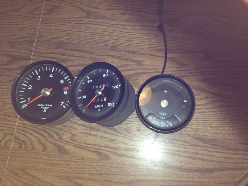 2nd step, drink a beer or two. This is somewhat unnerving and for the few it may turn you off. However, this isn't all that bad. We need to remove the bezel trim rings. I'm sure there is a machine out there that cost 15k, that will do this in about 10 seconds but we will use a small screwdriver. The first time I did this (my gauges) it took around 40 mins each, and I had a good size blister on my index finger. You will get a feeling that you are absolutely ruining these rings, but your not. Wedge the screw driver in between the bezel and the gauge can. Once your in, lightly twist back and forth the screw drive in situ pushing in a forward direction. By the time you get to the third gauge, you'll be a pro! I also found that it is unnecessary to uncrimp the entire circumference of the bezel ring. Once you get 3/4 around, the last 1/4 will pop off. 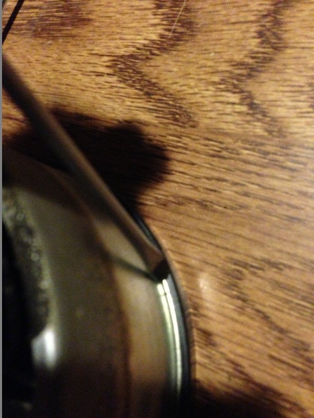 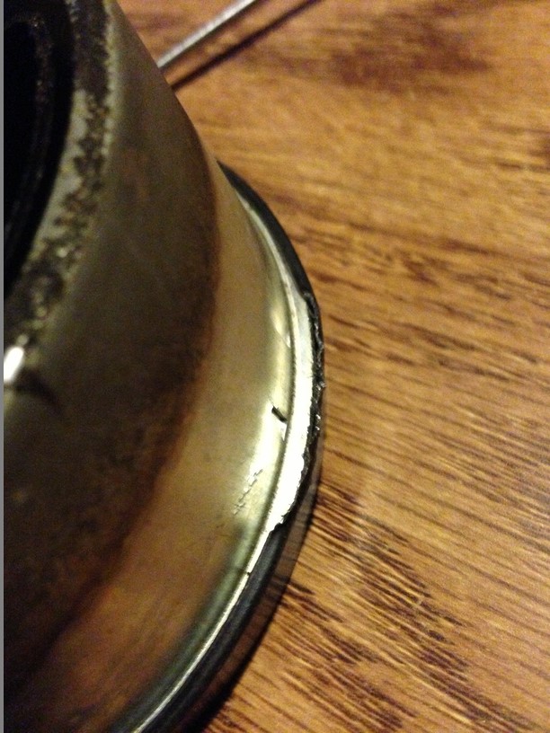 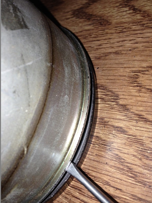 Now that these ring are off, go ahead and remove the insides. The tach will have 4 brass screws and the odometer will have 2. The combo gauge will have either 4 or 8 screws depending on the year. 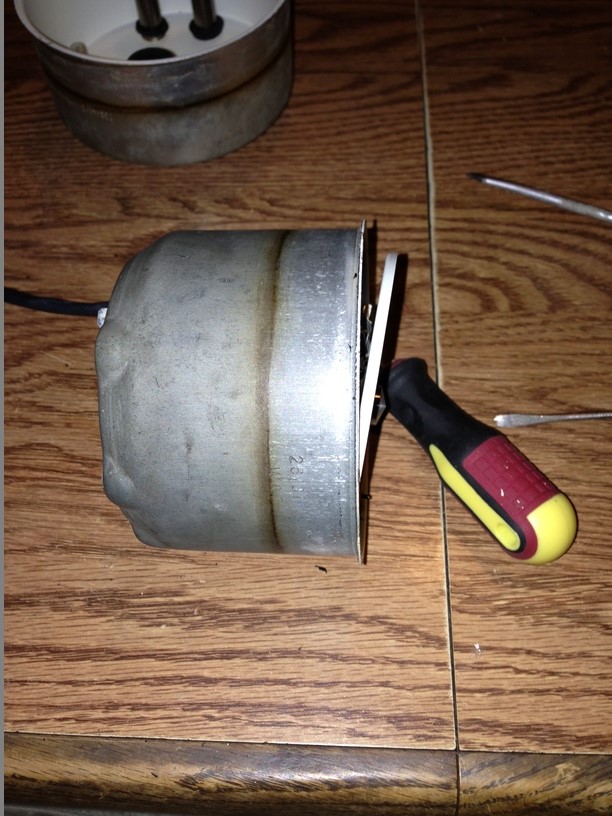 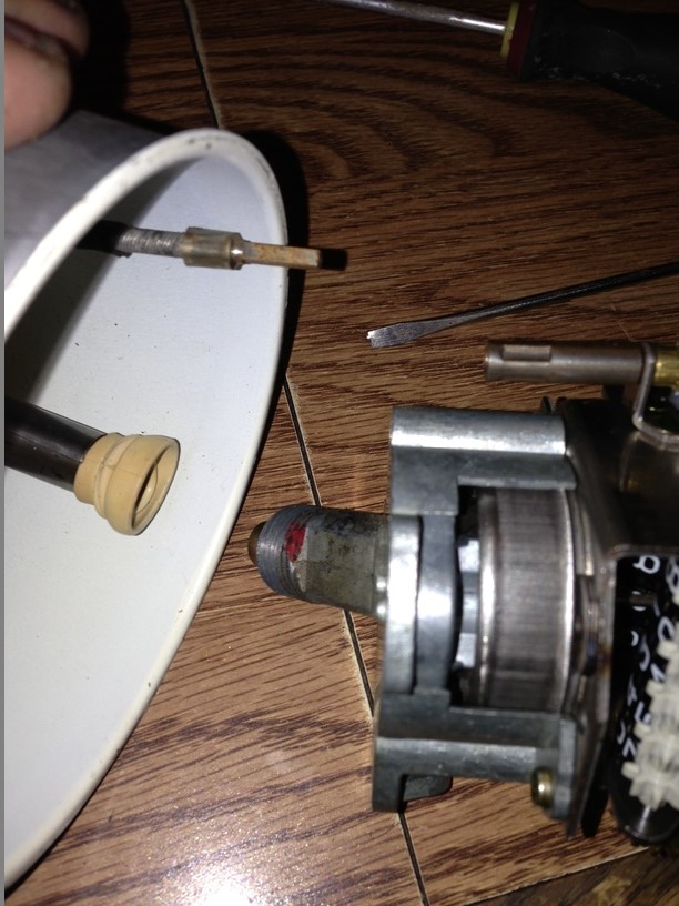 Now that the inner guts have been removed, you should have 3 empty cans like this 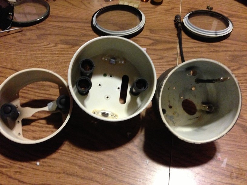 We will need to clean the inside of these cans, for the best adhesion of the LED lights in a future step. I didn't use anything special, good old windex spray should suffice. 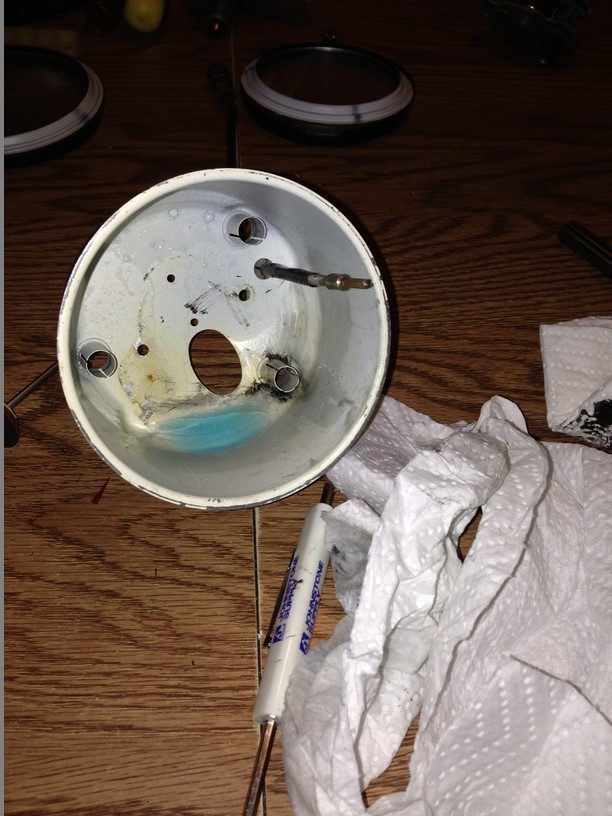 |
   |

 
|
  |
Replies(1 - 19)
| timothy_nd28 |
Jun 10 2013, 12:27 AM
Post
#2
|
|
Advanced Member Group: Members Posts: 2,299 Joined: 25-September 07 From: IN Member No.: 8,154 Region Association: Upper MidWest |
Since the inside guts are out and very accessible, this is a great time to perform some house keeping to sprucen them up.
This looks pretty shitty 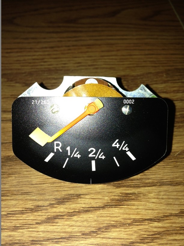 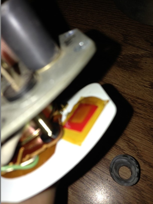 Notice the sun bleached needle and reserve fuel light window. This is resolved by purchasing a 3 dollar film gel swatch book. 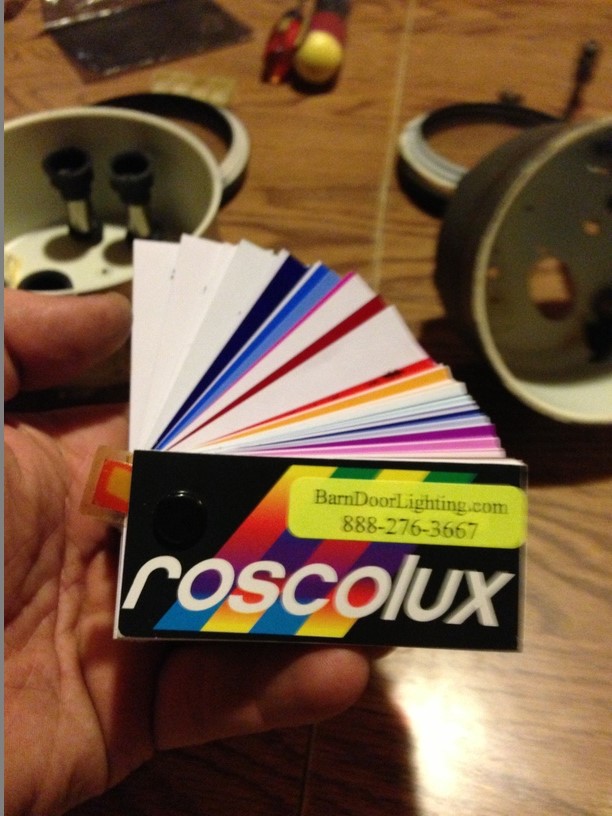 Many colors to choose from. Euro911 mentioned that these gauges came from his wife's car, so I was tempted to use pink. (IMG:style_emoticons/default/idea.gif) 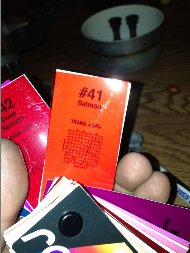 Some skillful scissor work and some masking tape, it is to my liking 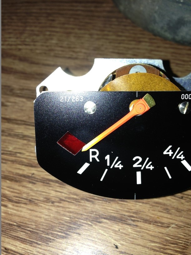 Another thing to consider while these are accessible is painting the needles. Refer back to the picture from step one, the needles are faded. Obtain a bottle of this. This bottle came from Corvette Central, but the color is very close to ours. 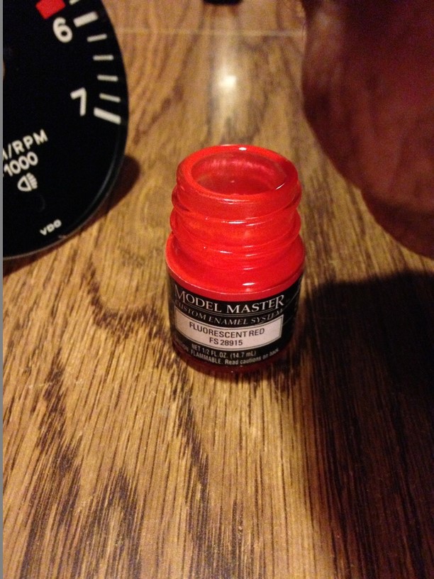 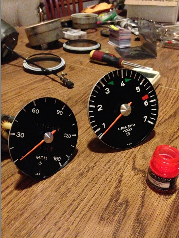 Take your time when painting them needles. I'm very pleased how these turned out. 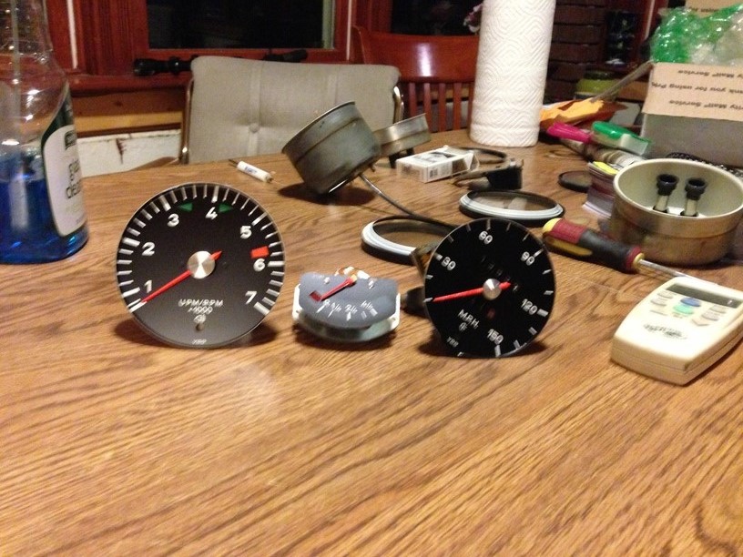 |
|
|
|
| timothy_nd28 |
Jun 10 2013, 12:28 AM
Post
#3
|
|
Advanced Member Group: Members Posts: 2,299 Joined: 25-September 07 From: IN Member No.: 8,154 Region Association: Upper MidWest |
Towards the LED's, there is a plethora of styles, shapes, and colors to choose from. For mine, I picked white side emitting led's on a flexible strip with adhesive style sticker. Ebay Led link
This is 60 cm long, and around 9 dollars each. You will need 2 of these to do all 3 gauges. By chance the above link doesn't work in the future, the spec for these LED's is 60cm long 335 SMD white LED flexible side emitting 60 led's. I choose this over others, because its side emitting, water proof, and high density of LED's per inch vs others I have seen. 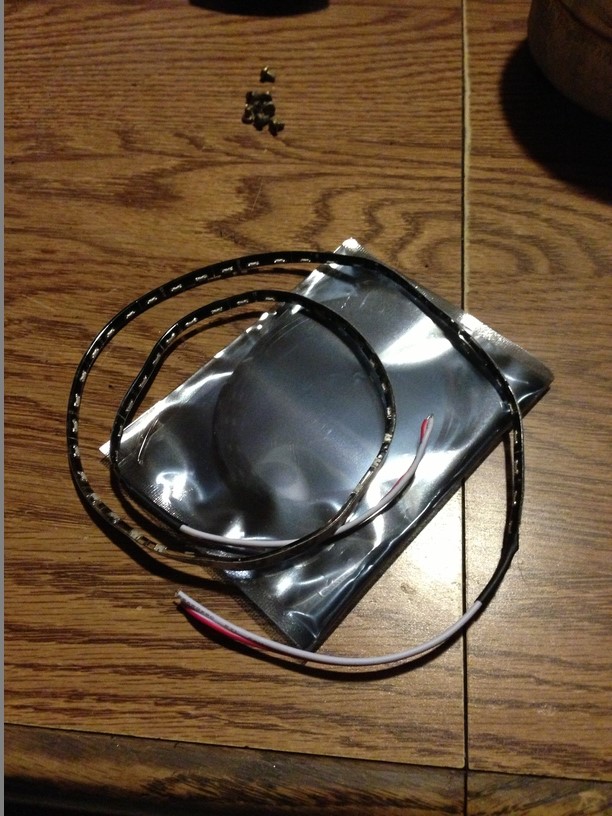 Okay, grab the speedometer can as we will start with this one. This is the largest of the 3 gauges and will utilize one of the two led strips you just bought. The flexible strip will have a white line on every 3rd led. This is where you're supposed to cut the strip. Make sure you cut exactly on this white strip, or you will render the LED strip useless. Mock up the LED flex strip so it wraps around the inside of the gauge. Once you have a good idea on total length, go ahead and cut it. 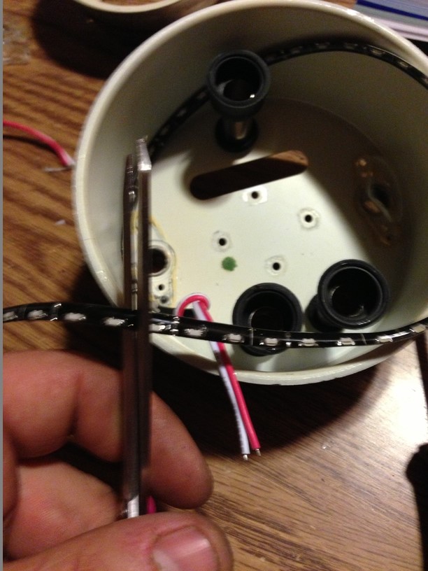 Next, tie a little knot in the wire, like this 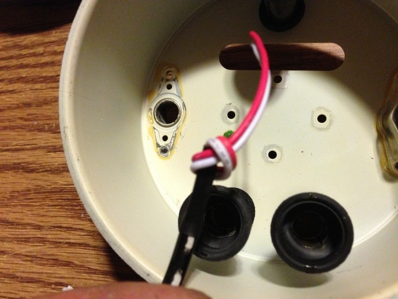 This knot will help act as a strain relief for the wire Go ahead and remove the sticker backing, and attach the LED strip. The wires must go thru the original light tube, and the knot must be inside this tube. Also, VERY IMPORTANT, these led strips are directional. Make sure these leds are facing forward before sticking them down!!! I typically install these strips about a 1/2" from the back of the gauge can. 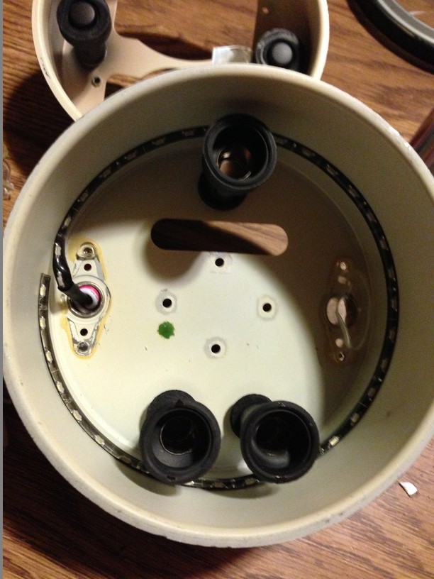 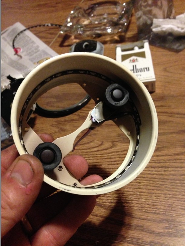 With the wires going thru the original light tube, take some clear RTV and squeeze some into the hole. This will keep the wires anchored, and you'll have less chance of ripping them out in the future. 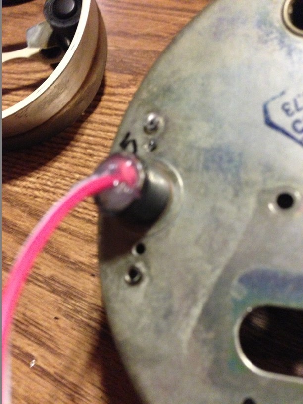 More house keeping, go ahead and clean the glass or plastic lenses 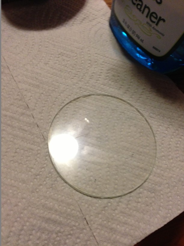 |
|
|
|
| timothy_nd28 |
Jun 10 2013, 12:28 AM
Post
#4
|
|
Advanced Member Group: Members Posts: 2,299 Joined: 25-September 07 From: IN Member No.: 8,154 Region Association: Upper MidWest |
Step 2 made me forget to take pictures of reassembly, for that I apologize. After these LED strips are installed, go ahead and reassemble each gauge. You will need to hook in the bezel ring (the small area that you didn't uncrimp) and pop in the rest. With your screw driver, carefully push down and re-crimp the bezel to the gauge can. This step is pretty straight forward.
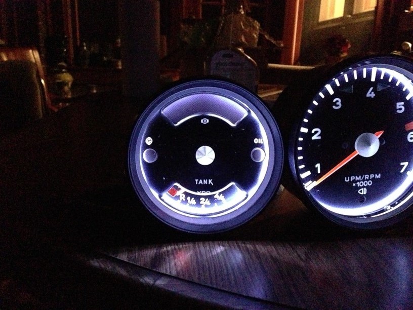
This is what it should look like after reassembly. Notice the pretty color on the needles 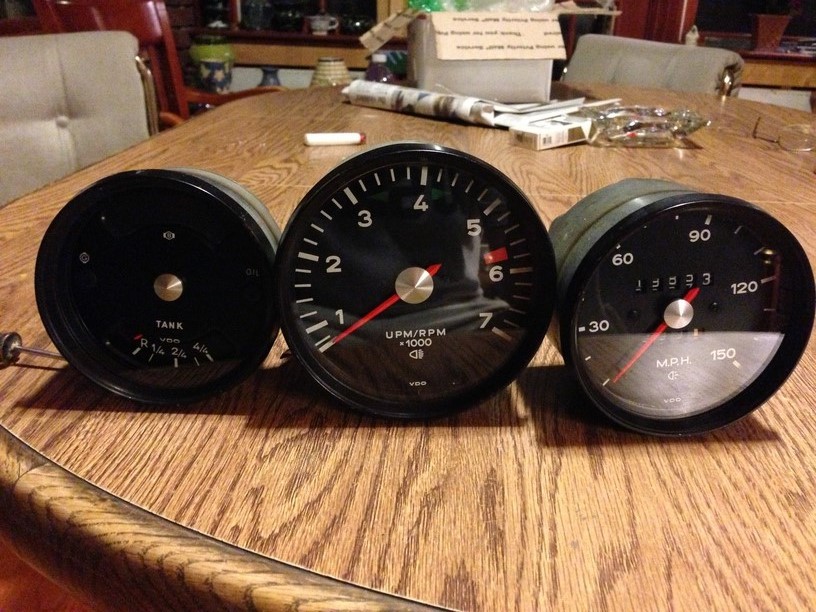 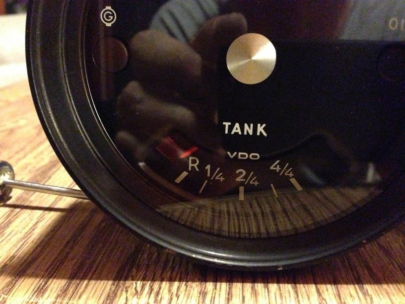 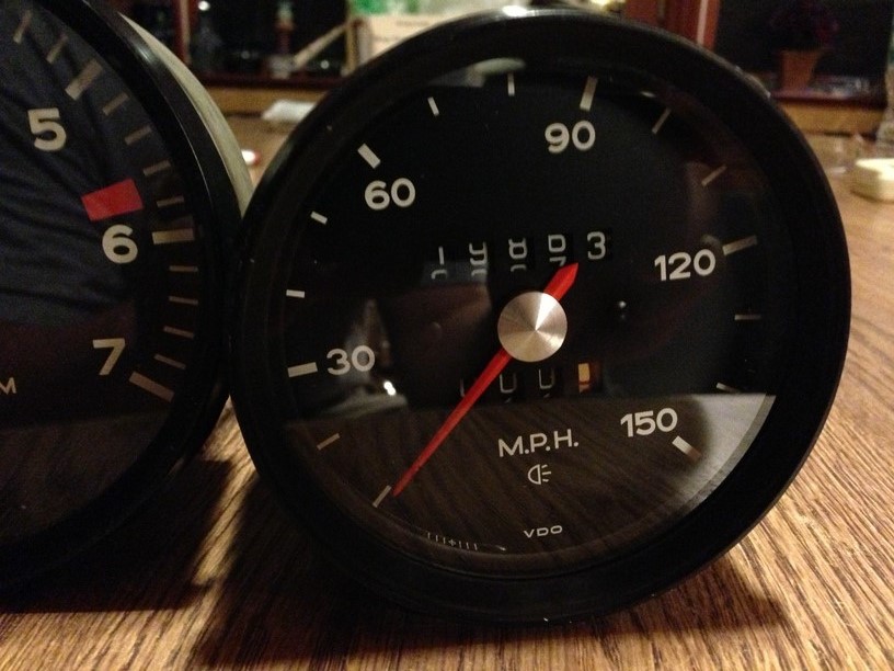 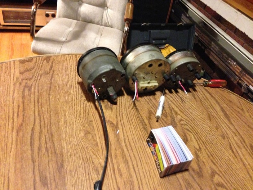 Now onto the wiring. We need to build a harness to jumper all the grounds together. You should have a brown wire that ties to the combo gauge, so we need to splice into this, without cutting wires. 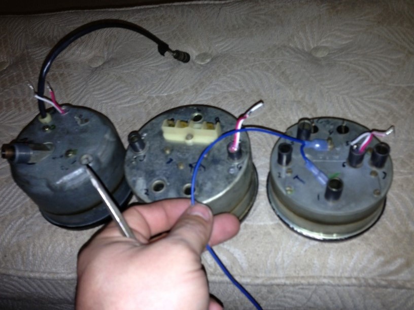 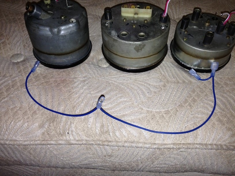 I should of used brown wire instead of blue, but this is all I had laying around. Obtain a piece of wire about 20" long or so. On one end, add a insulated 1/4" female terminal. Going from that terminal you just installed, move in about 10" and add another 1/4" female terminal. The opposite end of the wire gets abit squirrelly. We need to add 2 more female terminals and a male terminal (see picture). The male terminal will plug into the car's brown ground wire. The female on that end will plug onto the gauge where the brown used to go. This leaves you with 3 female terminals on the harness you just made that will plug into the (white) wires on the LED flex strip. White is ground on this flex strip, whereas red is positive. 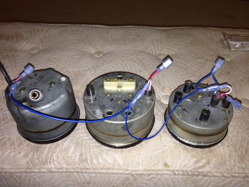 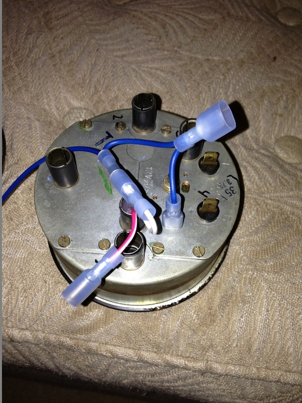 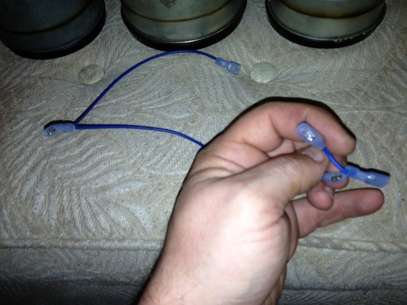 Towards the wires from the led flex strip (protruding the light tubes) you'll need to add male 1/4" insulated terminals to all the wires. This will mate with the harness you made with the car's electrical connectors. This makes for a pretty clean install. Keep in mind that the white wires are negative (ground) and the red are positive (+12vdc) Here is a diagram borrowed from Jeff Bowlsby's website to help aid with re-installation. 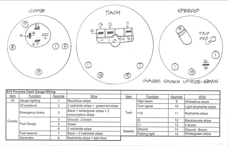 |
|
|
|
| timothy_nd28 |
Jun 10 2013, 12:29 AM
Post
#5
|
|
Advanced Member Group: Members Posts: 2,299 Joined: 25-September 07 From: IN Member No.: 8,154 Region Association: Upper MidWest |
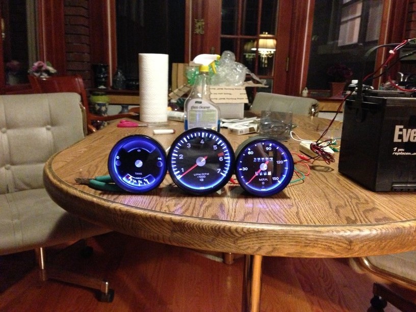
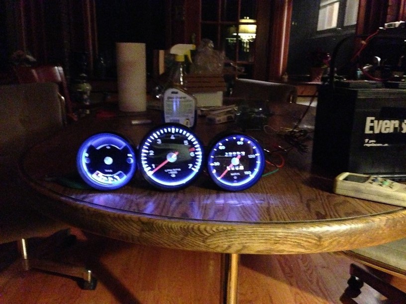
Here is the finished product. The camera made the pictures turn out abit blueish, however in person they look great and bright white. Using the car's stock rheostat, you can dim these down to a point, before they quit and go dark. Surprisingly they do dim down quite a bit. No need to add a PWM controller.
   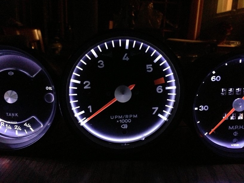 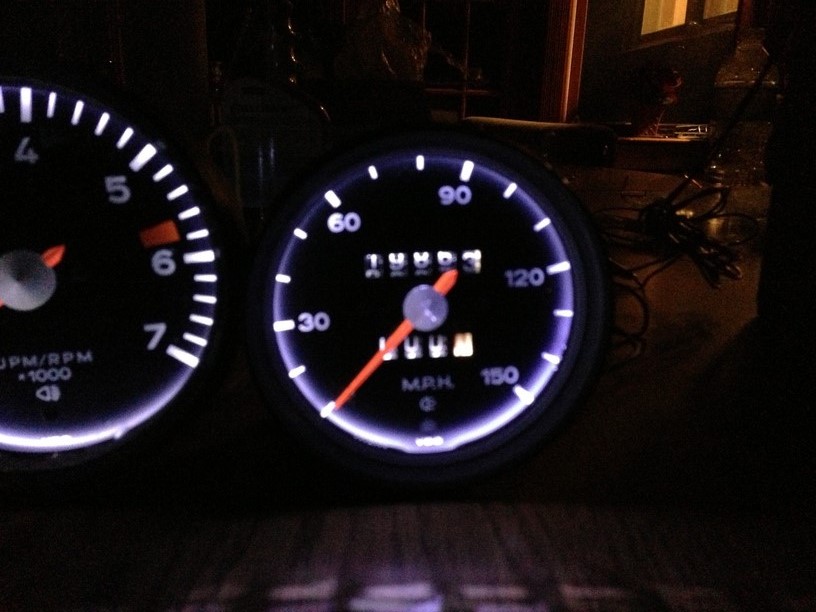 Hopefully you guys aren't intimidated with this project. The results will give you instant gratification. (IMG:style_emoticons/default/beerchug.gif) In the near future, I'll do a write up on Al's famous multi color gauges.  Attached image(s) 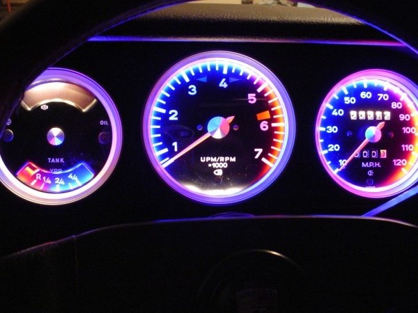
|
|
|
|
| r3dplanet |
Jun 10 2013, 12:38 AM
Post
#6
|
|
Senior Member Group: Members Posts: 679 Joined: 3-September 05 From: Portland, Oregon Member No.: 4,741 Region Association: None |
|
|
|
|
| bulitt |
Jun 10 2013, 01:54 AM
Post
#7
|
|
Achtzylinder Group: Members Posts: 4,189 Joined: 2-October 11 Member No.: 13,632 Region Association: South East States |
(IMG:style_emoticons/default/beerchug.gif) Thx for posting this!
|
|
|
|
| Chris H. |
Jun 10 2013, 08:59 AM
Post
#8
|
|
Senior Member Group: Members Posts: 4,059 Joined: 2-January 03 From: Chicago 'burbs Member No.: 73 Region Association: Upper MidWest |
Amazing work Tim! Thank you for the very detailed description. (IMG:style_emoticons/default/smilie_pokal.gif)
For anyone with later gauges you can also change the plexiglass (plastic) lens out for glass. Don't recall what year they went to plexi...'74 maybe? Pretty much eliminates the scratches permanently. |
|
|
|
| 76-914 |
Jun 10 2013, 09:20 AM
Post
#9
|
|
Repeat Offender & Resident Subaru Antagonist Group: Members Posts: 13,737 Joined: 23-January 09 From: Temecula, CA Member No.: 9,964 Region Association: Southern California |
Al would be proud of you. (IMG:style_emoticons/default/poke.gif) Now throw those cigarettes away before we have to place you next to Al. FWIW, I believe Al had a bunch of that stuff along with some gage and gage bodies. If your interested PM me and I'll check with Shirlee.
|
|
|
|
| ellisor3 |
Jun 10 2013, 09:34 AM
Post
#10
|
|
HPWhore Group: Members Posts: 811 Joined: 23-October 08 From: Fleming Island, Florida Member No.: 9,683 Region Association: South East States |
Great Tribute Thread. Al was a great guy, helped me get my gauges back together and even adjusted my speedo. Sorry he is gone. (IMG:style_emoticons/default/beerchug.gif)
|
|
|
|
| mrholland2 |
Jun 10 2013, 10:22 AM
Post
#11
|
|
Senior Member Group: Members Posts: 761 Joined: 7-September 11 From: Santa Maria,CA Member No.: 13,531 Region Association: Central California |
While my car is down, I would love to see the multi color method!!
|
|
|
|
| mrholland2 |
Jun 10 2013, 10:27 AM
Post
#12
|
|
Senior Member Group: Members Posts: 761 Joined: 7-September 11 From: Santa Maria,CA Member No.: 13,531 Region Association: Central California |
Oh, and are there LED instructions for the blinker indicators? Light/Bright light indicators? Oil/Generator? and Low Fuel?
Or do we have to stick with the old timey wimey light bulbs? |
|
|
|
| Spoke |
Jun 10 2013, 10:36 AM
Post
#13
|
|
Jerry Group: Members Posts: 7,186 Joined: 29-October 04 From: Allentown, PA Member No.: 3,031 Region Association: None |
Good write up.
Put this in the Classics Forum. |
|
|
|
| turk22 |
Jun 10 2013, 12:55 PM
Post
#14
|
|
Treetop Flyer Group: Members Posts: 735 Joined: 27-July 12 From: Cincinnati OH Member No.: 14,725 Region Association: Upper MidWest |
|
|
|
|
| poorsche914 |
Jun 10 2013, 03:51 PM
Post
#15
|
|
T4 Supercharged Group: Members Posts: 3,139 Joined: 28-May 09 From: Smoky Mountains Member No.: 10,419 Region Association: South East States |
Thanks for the write up. I have been planning to replace the plastic lenses in my guages with glass. The LED upgrade looks easy enough that I will do that as well. Might wait for the multi-color writeup, though (IMG:style_emoticons/default/smile.gif)
(IMG:style_emoticons/default/driving.gif) |
|
|
|
| timothy_nd28 |
Jun 10 2013, 10:33 PM
Post
#16
|
|
Advanced Member Group: Members Posts: 2,299 Joined: 25-September 07 From: IN Member No.: 8,154 Region Association: Upper MidWest |
QUOTE(mrholland2 @ Jun 10 2013, 08:27 AM)  Oh, and are there LED instructions for the blinker indicators? Light/Bright light indicators? Oil/Generator? and Low Fuel? Or do we have to stick with the old timey wimey light bulbs? I'd stick with the old timey wimey incandescent light bulbs. The light port tubes for these lamps direct most light straight thru. The resistance on the LED lamps are not the same as the incandescent bulbs, and could cause a problem with the flasher module. On my car, I did replace the indicators lamps (minus turn signal indicator). I wasn't impressed at all, as there was no noticeable difference between the LED vs the stock lamps. My next project will be the multi color setup, I will need a set of gauges from someone that is willing to let me try. I would also like to try a gauge setup with RGB led's. This would enable you to change the lighting to any color you can think of. The catch is finding a controller that turns on the RGB led's when power is applied to the controller. All controllers I've seen so far requires you to push the "on" button on the remote control for the LED's to turn on, this would be annoying. When you pull the headlight switch, you want the back lighting to come on with the headlight switch, not some silly remote control. So the search continues for the right controller. |
|
|
|
| euro911 |
Jun 11 2013, 02:13 AM
Post
#17
|
|
Retired & living the dream. God help me if I wake up! Group: Members Posts: 8,911 Joined: 2-December 06 From: So.Cal. & No.AZ (USA) Member No.: 7,300 Region Association: Southern California |
Wow. No, I mean WOW!
I really didn't know what to expect - they look awesome Tim! (IMG:style_emoticons/default/beerchug.gif) I need to fix the ODO gear when they arrive back here, but Tim wants me to install them and post some pix so we can all see what they look like installed. Since Dianne's car is torn apart, I guess I'll have to install them in the 'BB" for now (IMG:style_emoticons/default/laugh.gif) Send me your your Pay Pal info ... you are NOT getting away with doing these for nothing (IMG:style_emoticons/default/mad.gif) |
|
|
|
| pcar916 |
Jun 11 2013, 05:47 AM
Post
#18
|
|
Is that a Lola? Group: Members Posts: 1,523 Joined: 2-June 05 From: Little Rock, AR Member No.: 4,188 Region Association: None |
QUOTE(timothy_nd28 @ Jun 10 2013, 11:33 PM) The catch is finding a controller that turns on the RGB led's when power is applied to the controller. ... So the search continues for the right controller. Arduino microcontroller. You can make it trigger on any input you wish.... geez even temperature, vibration, ambient light conditions, whatever sensor you want to trigger on and with delay control as well. If you're ok with some breadboarding, this can run nearly the entire secondary electrical system. http://en.wikipedia.org/wiki/Arduino Cheap and many sources for both hardware and tutorials. Good luck |
|
|
|
| Steve |
Jun 11 2013, 11:53 AM
Post
#19
|
|
914 Guru Group: Members Posts: 5,890 Joined: 14-June 03 From: Laguna Niguel, CA Member No.: 822 Region Association: Southern California |
Thank you very much for posting this!!
I just bought the exact same paint at Hobby Lobby. My glass is scratched on a couple of my gauges. Is there a way to buff it out or where can you get new glass?? Thanks for the help!! |
|
|
|
| Madswede |
Jun 11 2013, 01:53 PM
Post
#20
|
|
Flat Out Driver Group: Members Posts: 853 Joined: 13-September 06 From: Rio Rancho NM Member No.: 6,831 Region Association: Rocky Mountains |
This is a shoo-in for the "Classic" forum. Well done sir! (IMG:style_emoticons/default/clap56.gif)
|
|
|
|
|
1 User(s) are reading this topic (1 Guests and 0 Anonymous Users)
0 Members:

|
Lo-Fi Version | Time is now: 10th July 2025 - 07:02 PM |
Invision Power Board
v9.1.4 © 2025 IPS, Inc.