|
|

|
Porsche, and the Porsche crest are registered trademarks of Dr. Ing. h.c. F. Porsche AG.
This site is not affiliated with Porsche in any way. Its only purpose is to provide an online forum for car enthusiasts. All other trademarks are property of their respective owners. |
|
|
| BuddyV |
 Jun 29 2013, 11:25 PM Jun 29 2013, 11:25 PM
Post
#1
|
|
Robert    Group: Members Posts: 555 Joined: 8-April 05 From: Santa Rosa, CA Member No.: 3,898 Region Association: Northern California 
|
If I was to remove a pair of pop-up lights and swap in a fiberglass hood that does not have the headlight cut-outs...... could you install lights in the fog light cut out ion the bumper with lights that would work well as headlights???
Street use.... although I almost never drive at night. I know this is done for race applications where the pop-up delete saves weight, etc. Just not sure it's a good idea for the street. .... wondering because of a few opportunities that have presented themselves. Cheers! |
  |
Replies(40 - 47)
| Dr Evil |
 Nov 29 2013, 10:08 PM Nov 29 2013, 10:08 PM
Post
#41
|
|
Send me your transmission!                Group: Members Posts: 23,002 Joined: 21-November 03 From: Loveland, OH 45140 Member No.: 1,372 Region Association: MidAtlantic Region 
|
Yup, precisely. I have seen a 914 kit where the lights pop up only enough, but when you turn the lights off the actuators fully cycle so it opens way wide before closing. This seems silly. But given the design of the lights, it's what's easy (you just cut/remove some of the trace on the rotary switch that powers the lights as they go up...). QUOTE [The easiest way for the DIY person would be to change the geometry on the actuator. This is what Mike B was referring to. I am considering an electronic option that opens to a level determined by the adjustment of a knob, and then closes without going through the whole sequence (goes in reverse, instead). This gives me something to mess with in my free time....gonna be a while. The other half of the challenge is finding the right light assembly to mount in your new, sleepy lights... Nope. If you cut the rotary part of the switch if will either open or close, but the circuit will not complete. The geometry is the easiest way, but takes trial and error with most people. Thus, my question about a circuit that can be installed and give you whatever you want. Maybe, once I get access to a headlight set in a car I can do some measurements and post them for different heights or post up a spread sheet. That seems the best way to go and would help the most. (IMG:style_emoticons/default/smile.gif) |
| mikesmith |
 Nov 30 2013, 02:56 AM Nov 30 2013, 02:56 AM
Post
#42
|
|
Member   Group: Members Posts: 202 Joined: 5-September 13 From: SF Member No.: 16,354 Region Association: Northern California |
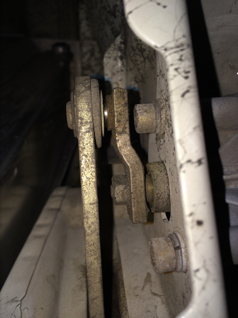
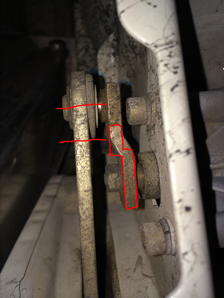
But given the design of the lights, it's what's easy (you just cut/remove some of the trace on the rotary switch that powers the lights as they go up...). Nope. If you cut the rotary part of the switch if will either open or close, but the circuit will not complete. If you open up the gap in the "hot to open" ring, you can make it stop earlier. But I agree, this isn't really useful (plus you can get the lights 'stuck' more open than you want them if you flip them off then on again quickly. QUOTE The geometry is the easiest way, but takes trial and error with most people. Thus, myquestion about a circuit that can be installed and give you whatever you want. Maybe, once I get access to a headlight set in a car I can do some measurements and post them for different heights or post up a spread sheet. That seems the best way to go and would help the most. (IMG:style_emoticons/default/smile.gif) I'm not sure that it makes sense to have a knob to adjust things - if you're going to mess with your lights there's a single target height that's 'right' once you're done messing with them. From a hacking perspective, I think you could get away with a couple of Heim joints and some threaded rod replacing the pushrod, and a modified crank that lets you move the pivot closer to the driveshaft.  There are a couple of issues in the above; there's not much room to move the pivot closer to the driveshaft with the existing crank design, and the gearbox mount bolt clearance is kinda tight, but I suspect someone with fabrication skill wouldn't find that much of a challenge... (IMG:style_emoticons/default/idea.gif) |
| euro911 |
 Nov 30 2013, 07:22 AM Nov 30 2013, 07:22 AM
Post
#43
|
|
Retired & living the dream. God help me if I wake up!      Group: Members Posts: 8,849 Joined: 2-December 06 From: So.Cal. & No.AZ (USA) Member No.: 7,300 Region Association: Southern California 
|
I think you've got it (IMG:style_emoticons/default/idea.gif)
It would take some experimentation, but shortening the actuating arm looks like it would do the trick.  |
| r_towle |
 Nov 30 2013, 08:56 AM Nov 30 2013, 08:56 AM
Post
#44
|
|
Custom Member                Group: Members Posts: 24,584 Joined: 9-January 03 From: Taxachusetts Member No.: 124 Region Association: North East States 
|
I think you've got it (IMG:style_emoticons/default/idea.gif) It would take some experimentation, but shortening the actuating arm looks like it would do the trick.  Not looking at the moment, so please don't yell at me. Lengthening or repositioning the other end of the long actuator arm would also do the same thing, and might be easier to fabricate? Meaning that wherever the long arm is connected to the headlight assembly, move that pivot point farther away from the headlight bucket pivot point ..... Not sure if there is room, again, I am not looking at it, but I suspect it may be a lot easier than making that little piece bolted onto the motor.... A bar with a slot to start so you can fine tune the adjustment length, then once you get it right, make another bar with a hole. |
| Dr Evil |
 Nov 30 2013, 10:37 AM Nov 30 2013, 10:37 AM
Post
#45
|
|
Send me your transmission!                Group: Members Posts: 23,002 Joined: 21-November 03 From: Loveland, OH 45140 Member No.: 1,372 Region Association: MidAtlantic Region 
|
The reason for an adjustment knob on the electical one is because you will not have the same height requirement as someone else. Thus, you will need to adjust to your height and someone else to theirs. The unit would bypass/trick the stock parts so that it would open to your set height (by the knob) and then when you close them it would go in revers. If it can not be made plug-and-play then it will be no better than making specific arms for different setups.
|
| mikesmith |
 Nov 30 2013, 01:52 PM Nov 30 2013, 01:52 PM
Post
#46
|
|
Member   Group: Members Posts: 202 Joined: 5-September 13 From: SF Member No.: 16,354 Region Association: Northern California |
The reason for an adjustment knob on the electical one is because you will not have the same height requirement as someone else. Thus, you will need to adjust to your height and someone else to theirs. The unit would bypass/trick the stock parts so that it would open to your set height (by the knob) and then when you close them it would go in revers. If it can not be made plug-and-play then it will be no better than making specific arms for different setups. This is why I was talking about finding "the" light assembly, since you'd want a single fixed angle change for a given light setup, and unless you changed your light setup (or built a cantilever to keep the lights always level...) you wouldn't care about adjustability. With that said, making the motor do what you're describing won't be hard. It's externally grounded and should easily run backwards. Position sensing (i.e. what is the knob setting compared against?) will be more difficult; you could conceivably replace the existing switch rotor with one with a resistive coating, but unless you can find a stock part that's easily modified to drop in it's going to be expensive getting a custom built. If you were willing to have a fixed number of discrete steps, you could build a simpler rotor replacement emulating a two-wire rotary encoder. There are a bunch of unknowns here (how fat is the contact patch when the fingers wear? how much lash or overrun should you assume?) but you could probably do this with a regular single-sided PCB and have them made inexpensively. Then it's just a pair of relays and a small compute device to read the encoder, knob and control signals. |
| Dr Evil |
 Nov 30 2013, 02:03 PM Nov 30 2013, 02:03 PM
Post
#47
|
|
Send me your transmission!                Group: Members Posts: 23,002 Joined: 21-November 03 From: Loveland, OH 45140 Member No.: 1,372 Region Association: MidAtlantic Region 
|
Your words make sense for whatever design you have in your head. You don't know what I am doing/planning. The problems and parameters do not apply to what I would design.
|
| Dr Evil |
 Nov 30 2013, 02:33 PM Nov 30 2013, 02:33 PM
Post
#48
|
|
Send me your transmission!                Group: Members Posts: 23,002 Joined: 21-November 03 From: Loveland, OH 45140 Member No.: 1,372 Region Association: MidAtlantic Region 
|
Did not read last part. Smart phone and ADHD. Stepper with optocoupler is what I would use. Easy.
|
  |
1 User(s) are reading this topic (1 Guests and 0 Anonymous Users)
0 Members:

|
Lo-Fi Version | Time is now: 29th May 2024 - 12:38 AM |
Invision Power Board
v9.1.4 © 2024 IPS, Inc.


