|
|
|
Porsche, and the Porsche crest are registered trademarks of Dr. Ing. h.c. F. Porsche AG.
This site is not affiliated with Porsche in any way. Its only purpose is to provide an online forum for car enthusiasts. All other trademarks are property of their respective owners. |
|
|

  |

| timothy_nd28 |
 Jul 2 2013, 04:00 PM Jul 2 2013, 04:00 PM
Post
#1
|
|
Advanced Member  Group: Members Posts: 2,299 Joined: 25-September 07 From: IN Member No.: 8,154 Region Association: Upper MidWest |
First I would like to thank Kent (76-914) for introducing me to Al's wife Shirlee. She was extremely helpful and sold me all of Al's leftovers. Today, I received a huge box filled with led's, cannibalized gauge housings and a very touching note from Shirlee. I also noticed a dismantled tachometer that Al was working on. I was taken back and felt very sad seeing this tach. You could see all the tedious prep work that Al did, but sadly he wasn't able to complete his masterpiece.
I was determined this afternoon to pick-up where Al had left off, in his honor. This thread is broken up in 3 parts. The first part is intended to show everyone how Al achieved his multicolor gauges. The 2nd part is a "how to" to make your gauges into any color you wish. The last part is another "how to" but taking our gauges to a whole new level. As you will see, my design could have a back light color background in any color that you can think of. My uncle has designed a neat little circuit that works in tandem with the RGB color controller. The circuit senses the tach wire, and changes the color of the back-lighting of all gauges to yellow at a certain rpm, then red at another certain rpm. It is fully customizable as you can set the when yellow comes on, as well as the red. There is another input on this circuit board which turns all the gauges to red when triggered. I thought we could use this special input for the low fuel light, or as a fan belt warning for the 911 types. Perhaps the special input could be hacked into a radar detector, many possibilities. Yellow and redline lights again are fully adjustable via a potentiometers, also this circuit will work for any 4-6-8 cylinder engines. With my last how-to topic, I received many messages from folks that didn't feel comfortable doing this to their own gauges. I have done enough of these in which I feel comfortable. If you're one of these folks, send me a PM and I'll do this conversion for you. For me, it's a 1.5 hour process, but it may take longer for someone that has never done something like this before. I'll try to make this write up detailed as much as possible. |
   |

 
|
| timothy_nd28 |
Jul 2 2013, 04:01 PM
Post
#2
|
|
Advanced Member Group: Members Posts: 2,299 Joined: 25-September 07 From: IN Member No.: 8,154 Region Association: Upper MidWest |
Here is Al's unfinished gauge, most likely a 75-76 era tachometer
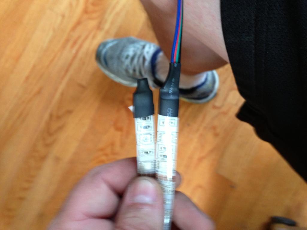
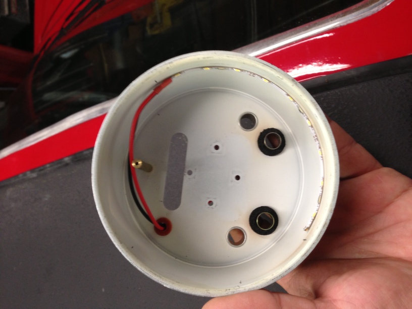  Keep in mind, this is what we are after  I applied power to this gauge, and here was the results 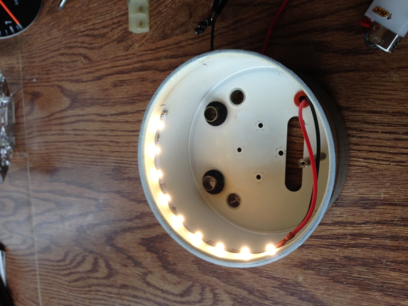 As you can see, this partial led strip is white. I'm not sure what Al was trying to do, but for his signature multicolor gauge, this is the wrong color. 1st step, reinstall the tach faceplate and make pencil marks inside the can at the RPM's you want. I chose 0 to 4.2 to be blue, 4.2 to redline to be white, then redline to around 7 to be red. The pencil line inside the gauge can is helpful with the mock up. Here is a picture of the style flexible LED strip Al used. I was happy to see that he used the same style side emitting led as I did, but his is not waterproof. I'm not a huge fan with this idea, due to the possibility of something shorting to ground. Our car catches fire readily enough, I hate to add to the list of potential fire starting causes. This is why I use waterproof led flex strips. 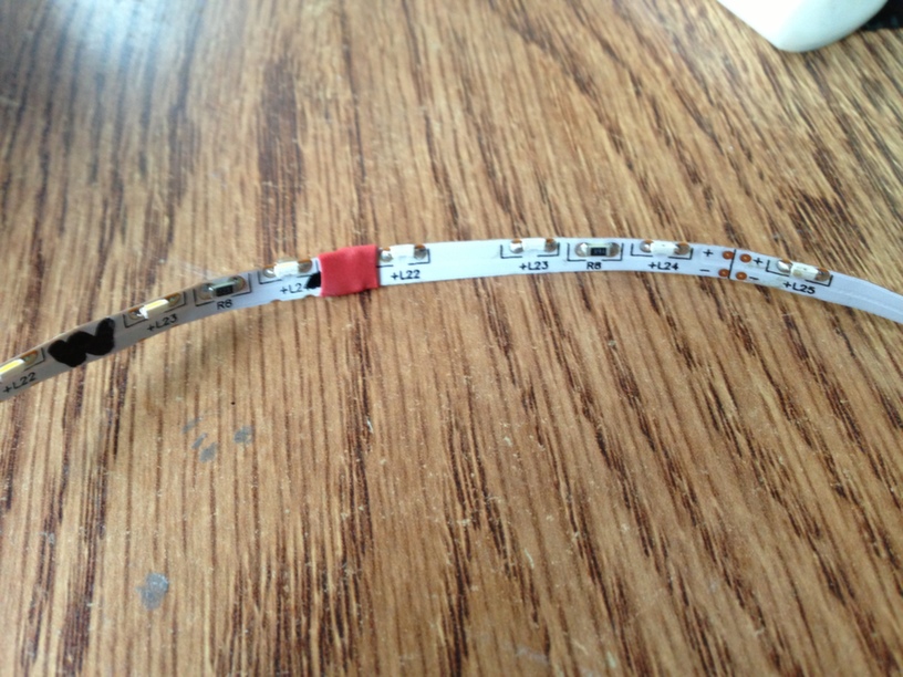 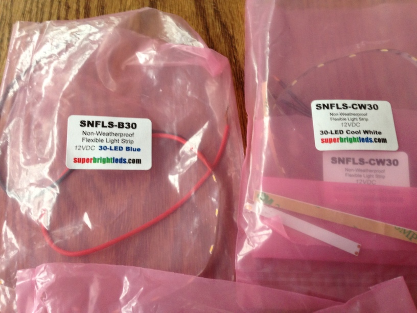 |
|
|
|
| timothy_nd28 |
Jul 2 2013, 04:01 PM
Post
#3
|
|
Advanced Member Group: Members Posts: 2,299 Joined: 25-September 07 From: IN Member No.: 8,154 Region Association: Upper MidWest |
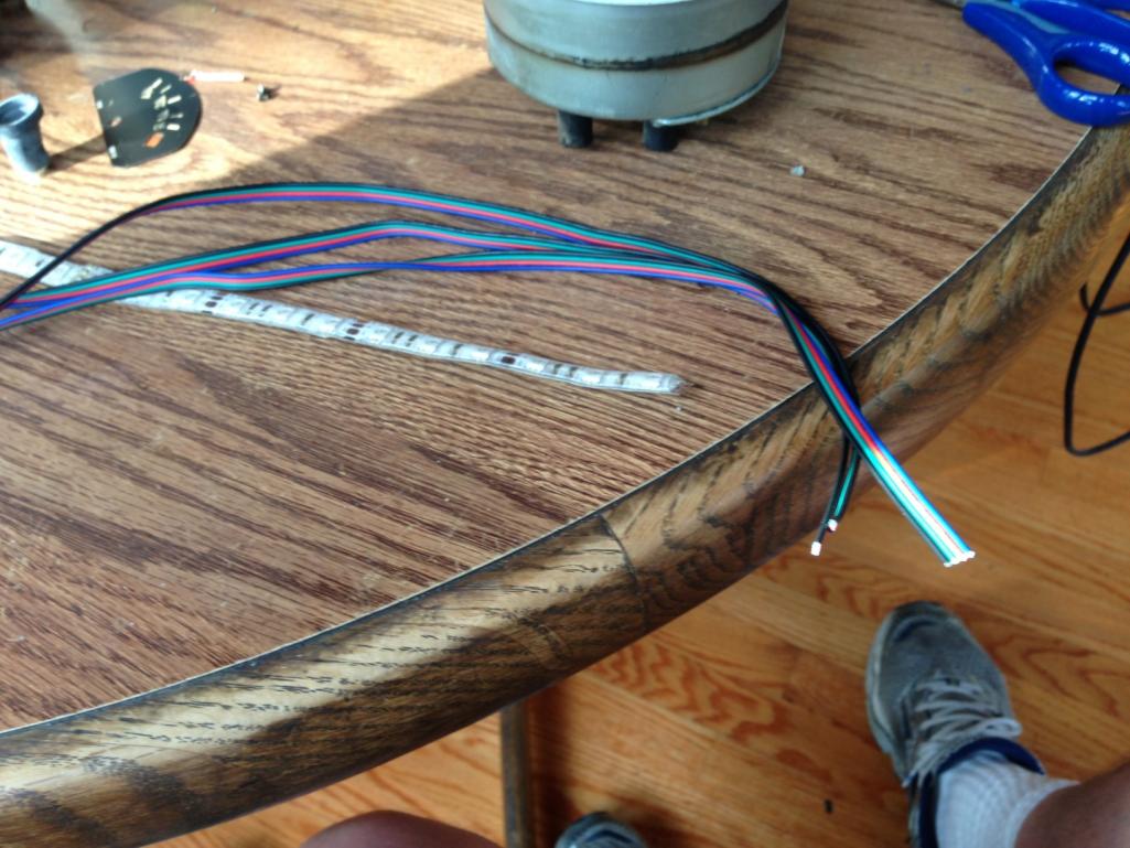
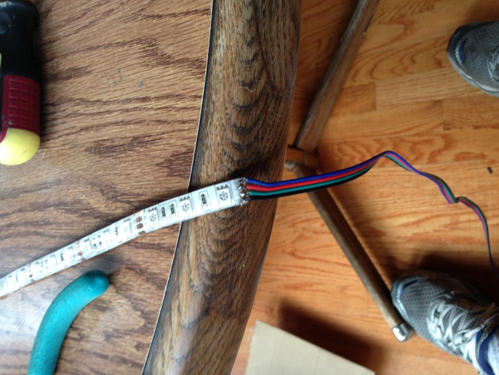
Next, we need to build a continuous strip with different colors. This led strip is made to be cut every 3 led's. This will require you to solder this flexible circuit boards together.
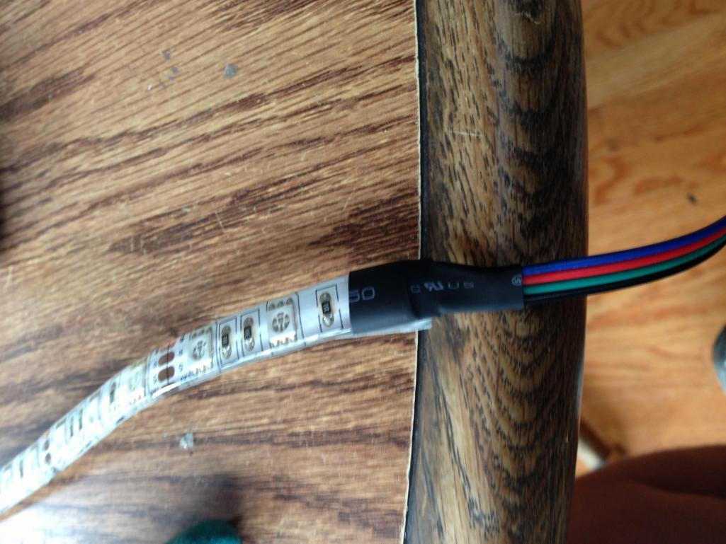
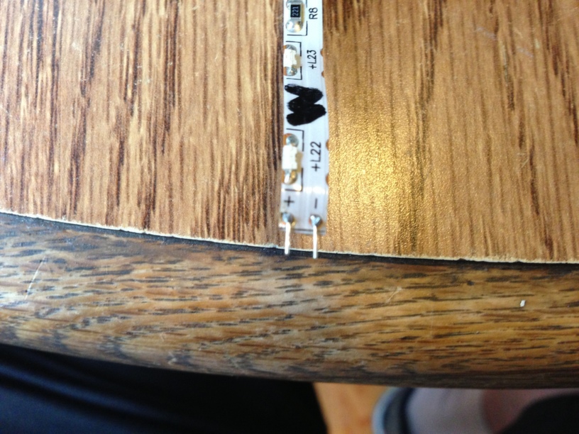 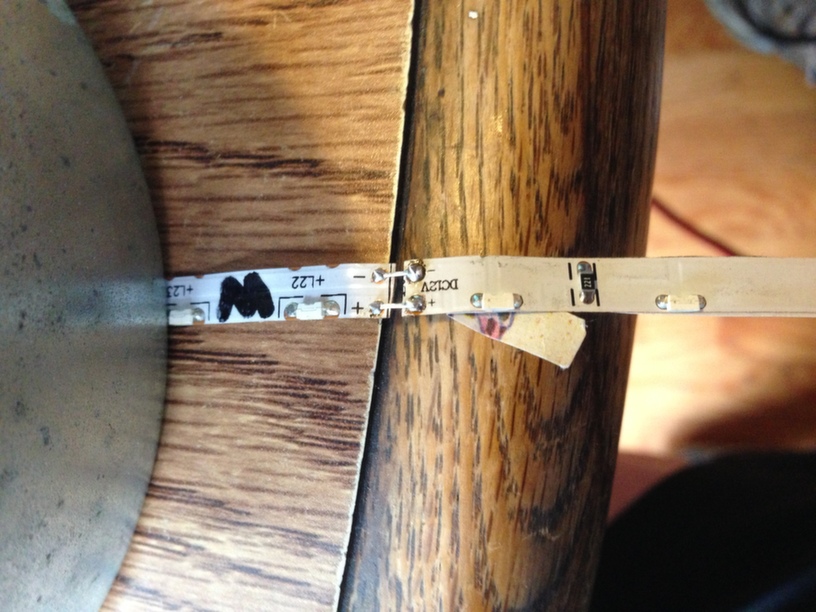 Be sure to use heat shrink around these soldered connections! 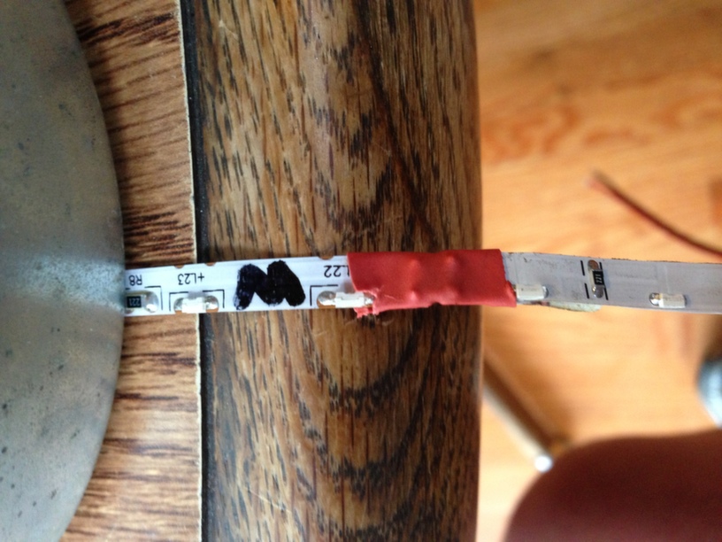 Now with your strip soldered together, this is a good time to test your creation 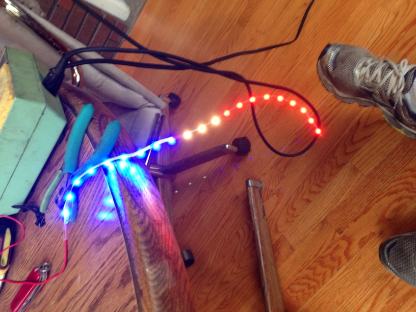 |
|
|
|
| timothy_nd28 |
Jul 2 2013, 04:01 PM
Post
#4
|
|
Advanced Member Group: Members Posts: 2,299 Joined: 25-September 07 From: IN Member No.: 8,154 Region Association: Upper MidWest |
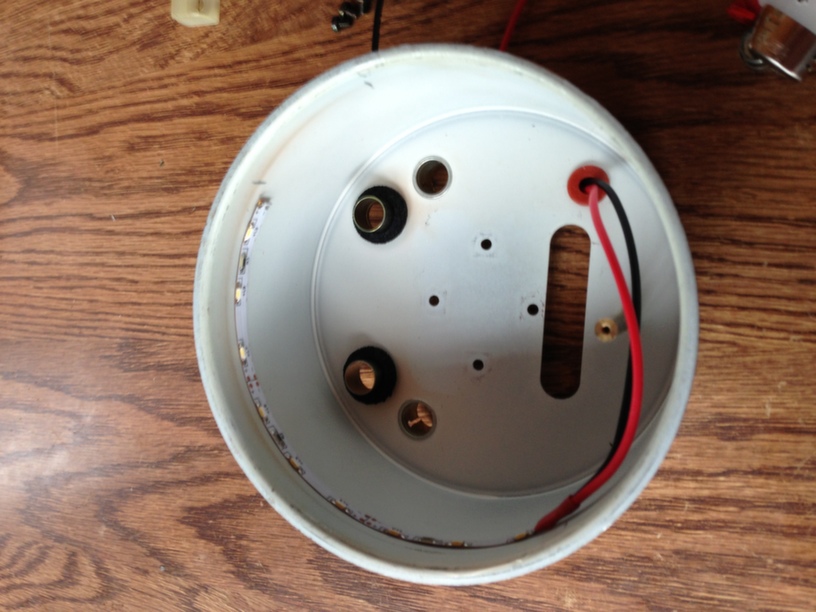
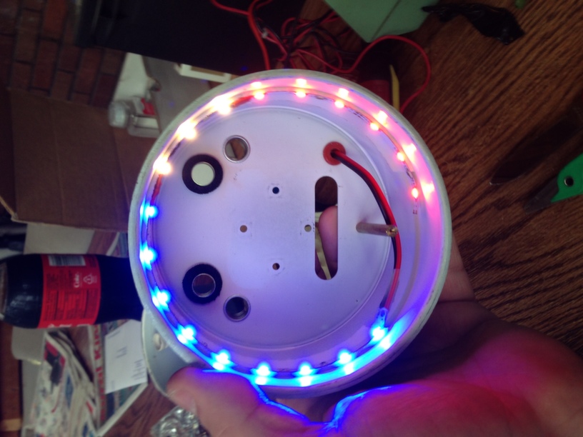
I have spoken my piece about using non waterproof led strips, so this is what I did to fix the problem. Obtain some foamy double sided tape and go ahead and line the inner gauge can. You want this foam tape to be about 1" back from the front of the can. This foam keeps the raw circuit tracks from shorting out to the gauge can. It also has another benefit, it lifts the flex strip from the can about 1/8". This is good, because mounting the flex strip right on the can and being so forward causes stray light to hit your eye or your passenger.
 Al did a nice job creating a new hole and grommet for the wires. This is not a bad thing, as it keeps the wire from chafing. 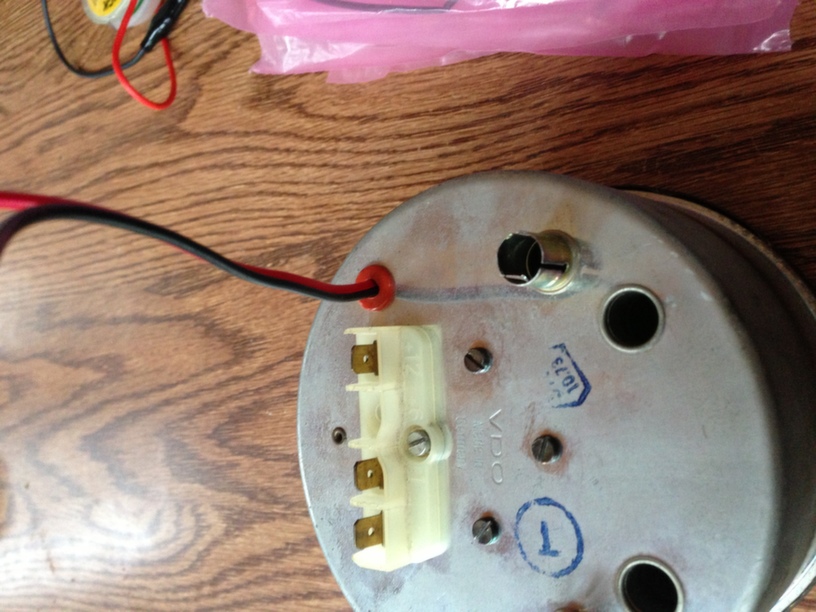 |
|
|
|
| timothy_nd28 |
Jul 2 2013, 04:01 PM
Post
#5
|
|
Advanced Member Group: Members Posts: 2,299 Joined: 25-September 07 From: IN Member No.: 8,154 Region Association: Upper MidWest |
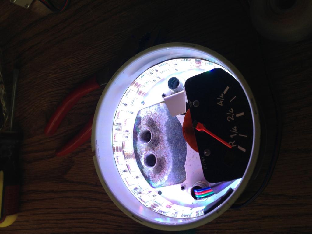
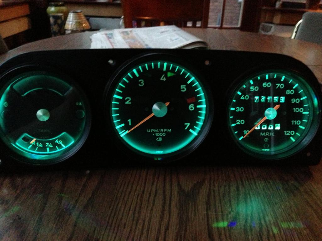
Now, just reassemble. Refer to my other topic and pay attention to step 2 if you need guidance.
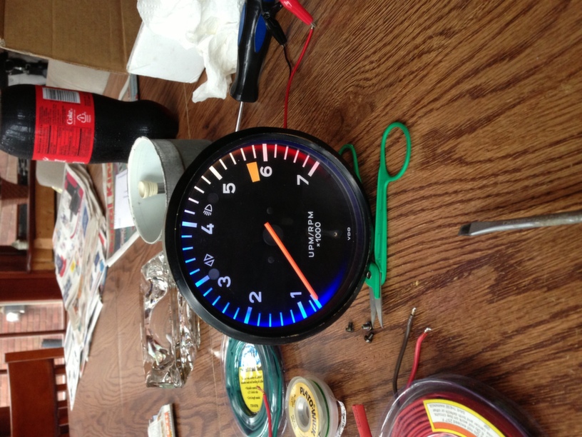 not bad 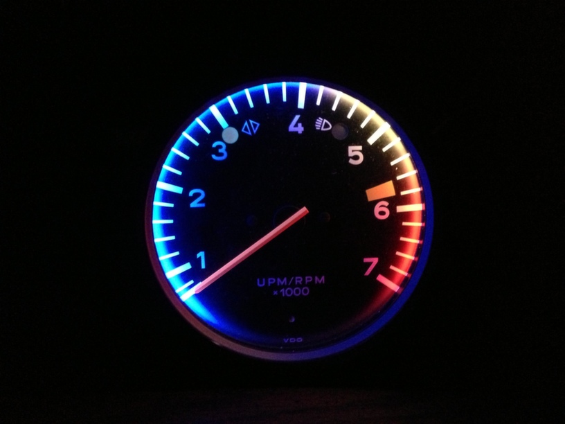 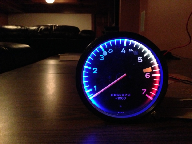 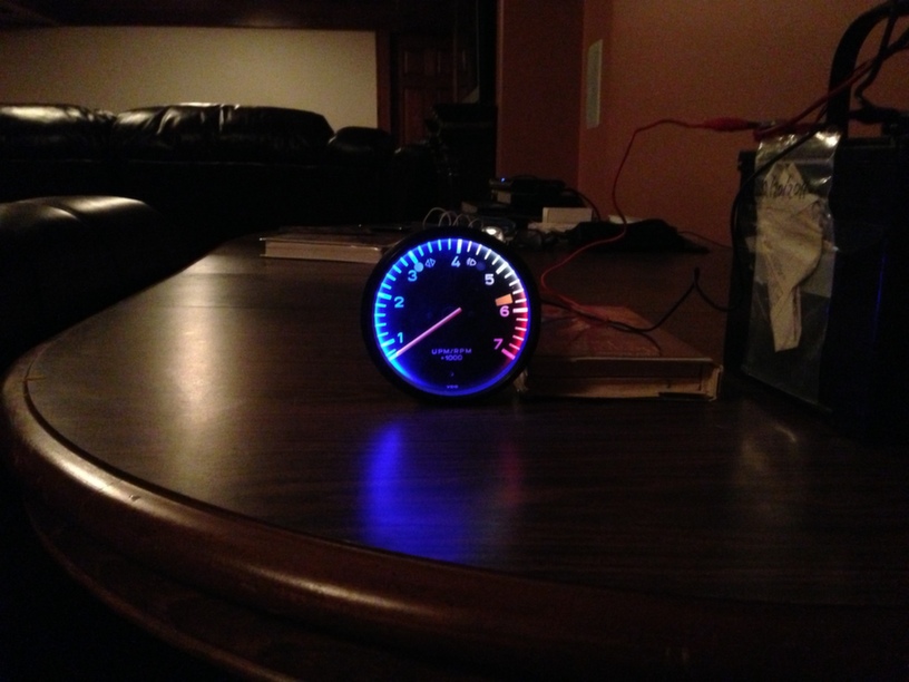 just as a reference 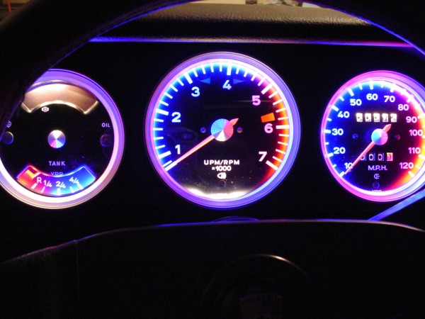 Hopefully I didn't do Al any injustice with my amature attempt. RIP Al |
|
|
|
| timothy_nd28 |
Jul 2 2013, 04:02 PM
Post
#6
|
|
Advanced Member Group: Members Posts: 2,299 Joined: 25-September 07 From: IN Member No.: 8,154 Region Association: Upper MidWest |
Now onto true multicolor gauges! This part explains how to install RGB led's into your gauges, which enables you to choose any color via a push of a button.
Refer to my last topic "gauge lighting" to assist with disassemble with the gauge cans. Thanks to Garold, he was brave enough to let me experiment on his gauge cluster. 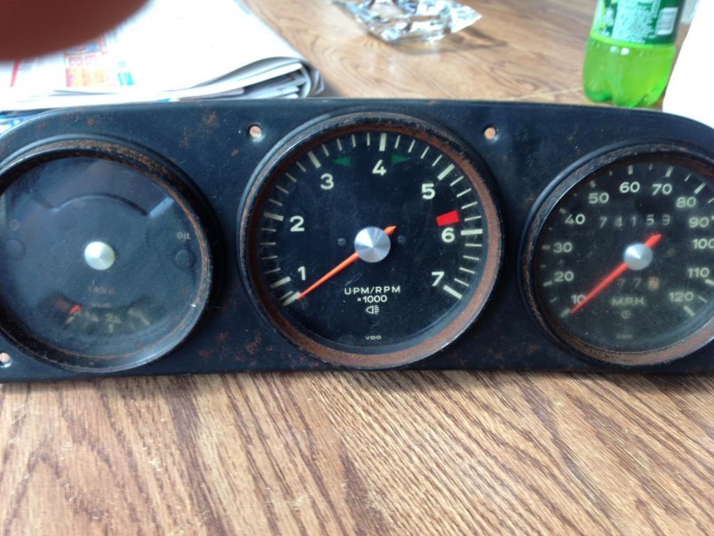 However, these are in pretty bad shape, but good enough for the proof of concept. First, remove the gauge bezel ring. Refer to my last topic 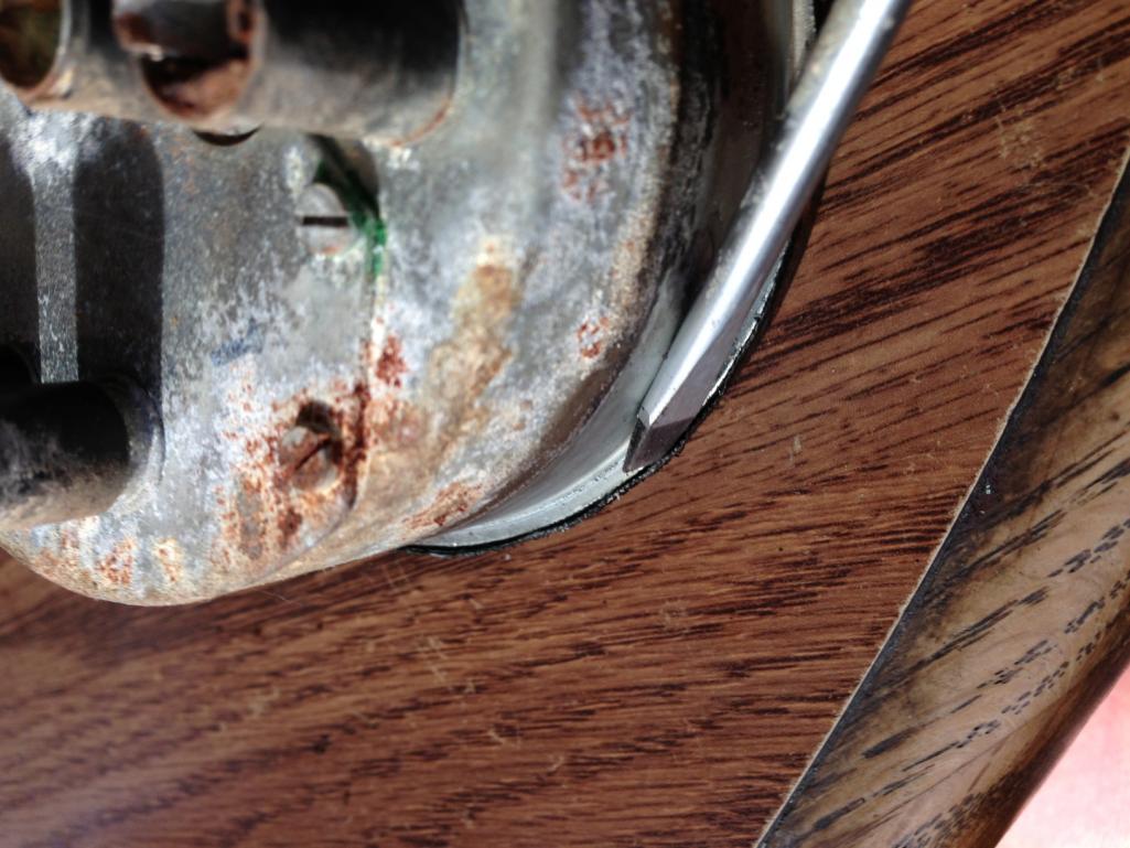 Next, obtain these led's, they are readily available on eBay. (RGB 5050 waterproof SMD flexible LED strips, 60 led per meter) 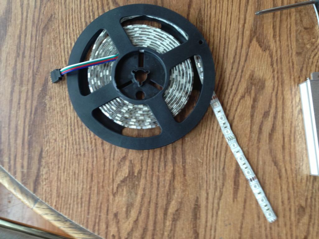 These led's are kinda cool, as they have red,green,blue all built into one single led. However, they don't sell them as side emitting like the style we used on the previous builds. Since they are not side emitting, we will need to do more then one loop inside the gauge can. I have found that 2 loops gives plenty of light. We will need to cut to length and solder on 18" or so of flat rgb cable. Then we need to peel back the silicone waterproofing material to expose the solder pads on the flexible circuit board. 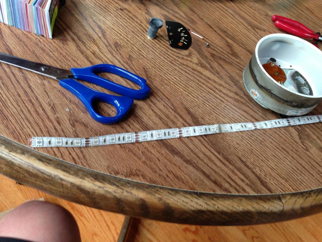 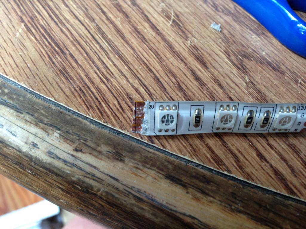 |
|
|
|
| timothy_nd28 |
Jul 2 2013, 04:02 PM
Post
#7
|
|
Advanced Member Group: Members Posts: 2,299 Joined: 25-September 07 From: IN Member No.: 8,154 Region Association: Upper MidWest |
    be sure to use heat shrink over your solder connections! Now, go ahead and peel the sticky tape and install inside the gauge can. I like them towards the back of the can, to limit stray annoying light. 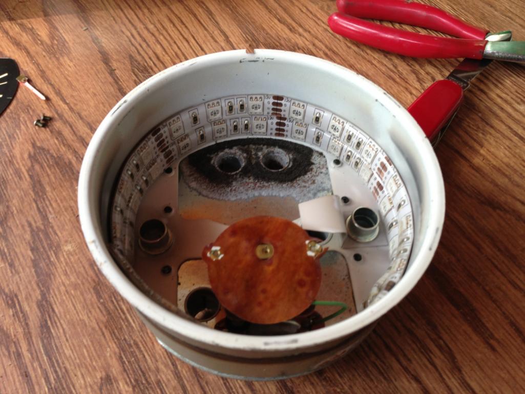 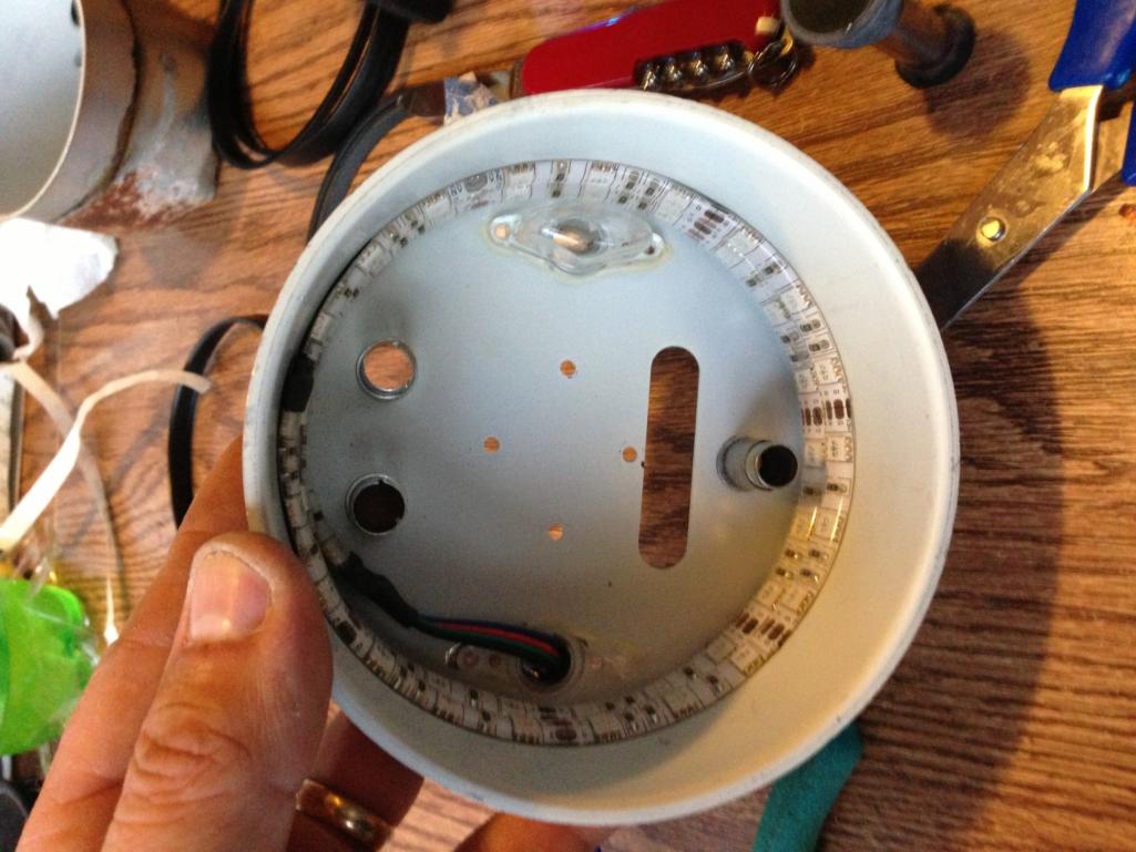 So far so good, repeat this for the remainder of your gauges. |
|
|
|
| timothy_nd28 |
Jul 2 2013, 04:03 PM
Post
#8
|
|
Advanced Member Group: Members Posts: 2,299 Joined: 25-September 07 From: IN Member No.: 8,154 Region Association: Upper MidWest |
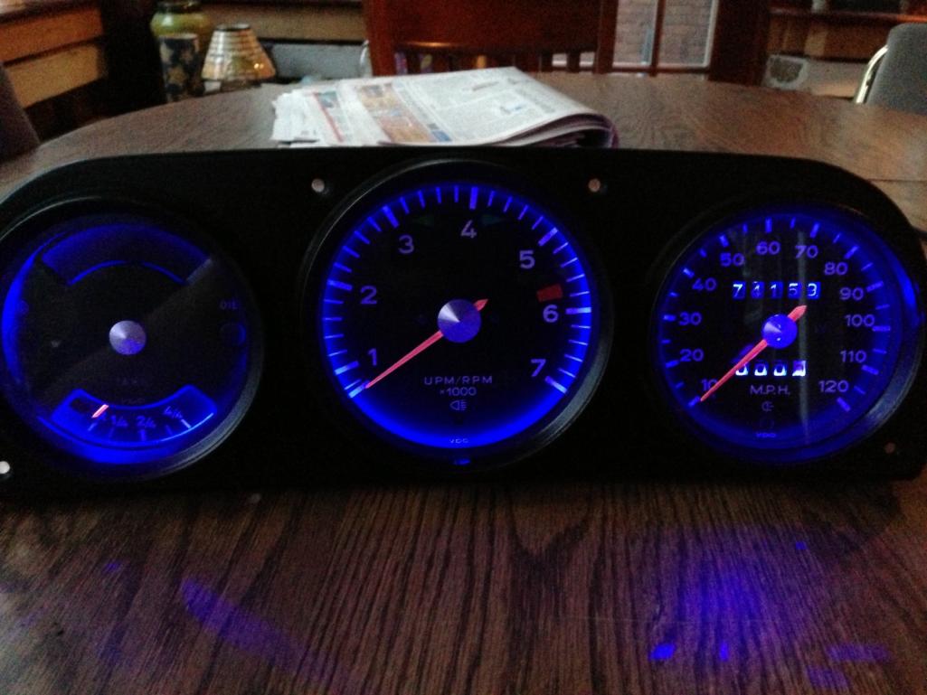
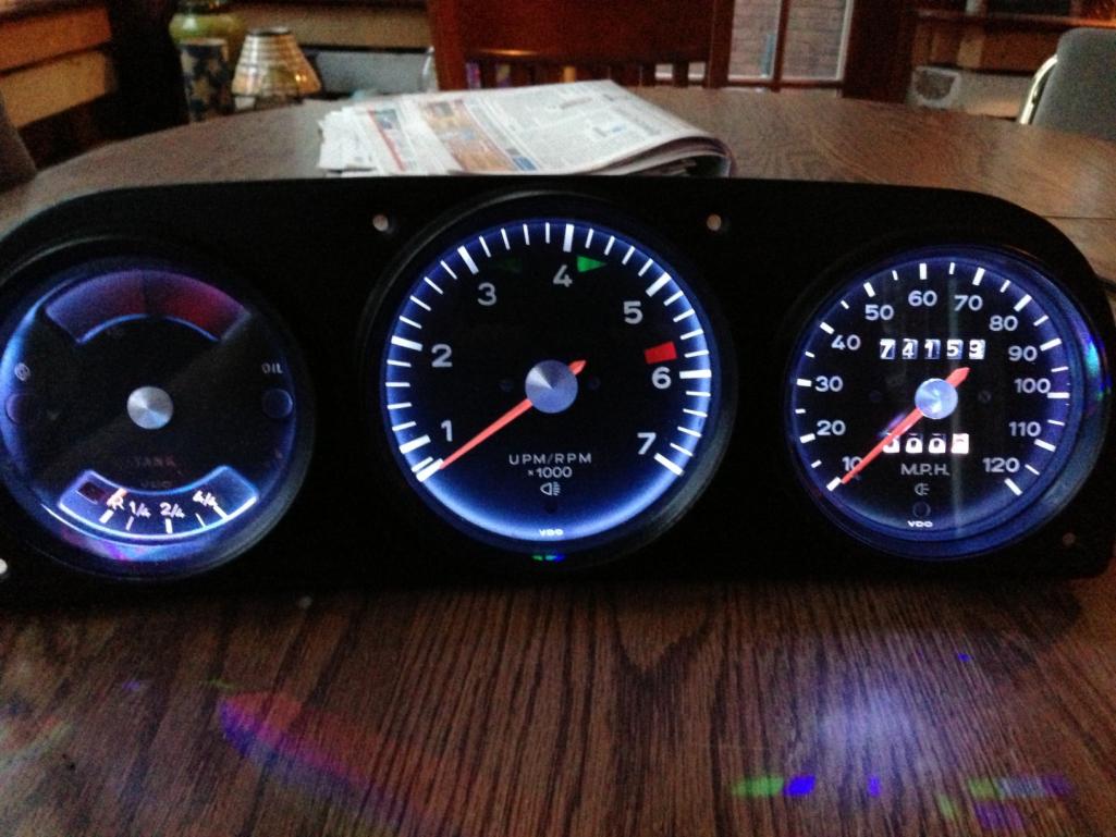
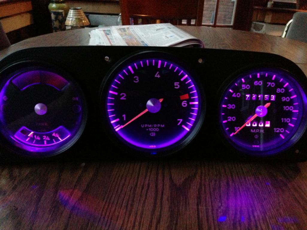
Go ahead and test these lights before putting the gauge back together.
 Let us now turn our attention to the controller. I have found a good cheap Chinese RGB controller that will work with our car. Readily available on eBay for 10 bucks, and the best part, it has memory. It would really suck to turn on the headlight switch and have your gauges go into some disco mode! You pick the color that you like best, and it retains that same color the next time you pull the headlight switch. Here's the controller: 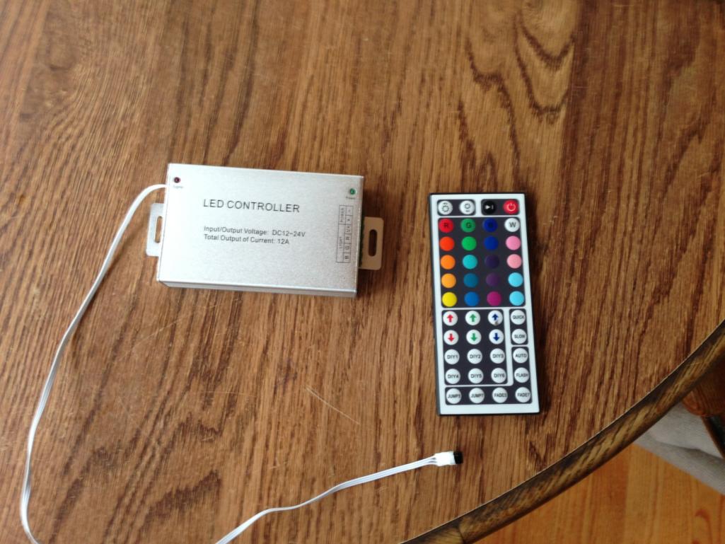 Here is a small sample of colors you can choose from. The pictures don't do these any justice, they look awesome in person. You can make any color, if you don't like any of the presets, you can manually adjust the red, blue and green to find the color you like best. They even have pink for the unicorn lovers (IMG:style_emoticons/default/drunk.gif) Set the color, and throw the remote into the glovebox and forget about it. For the purist, I think this color matches are original incandescent lamps. 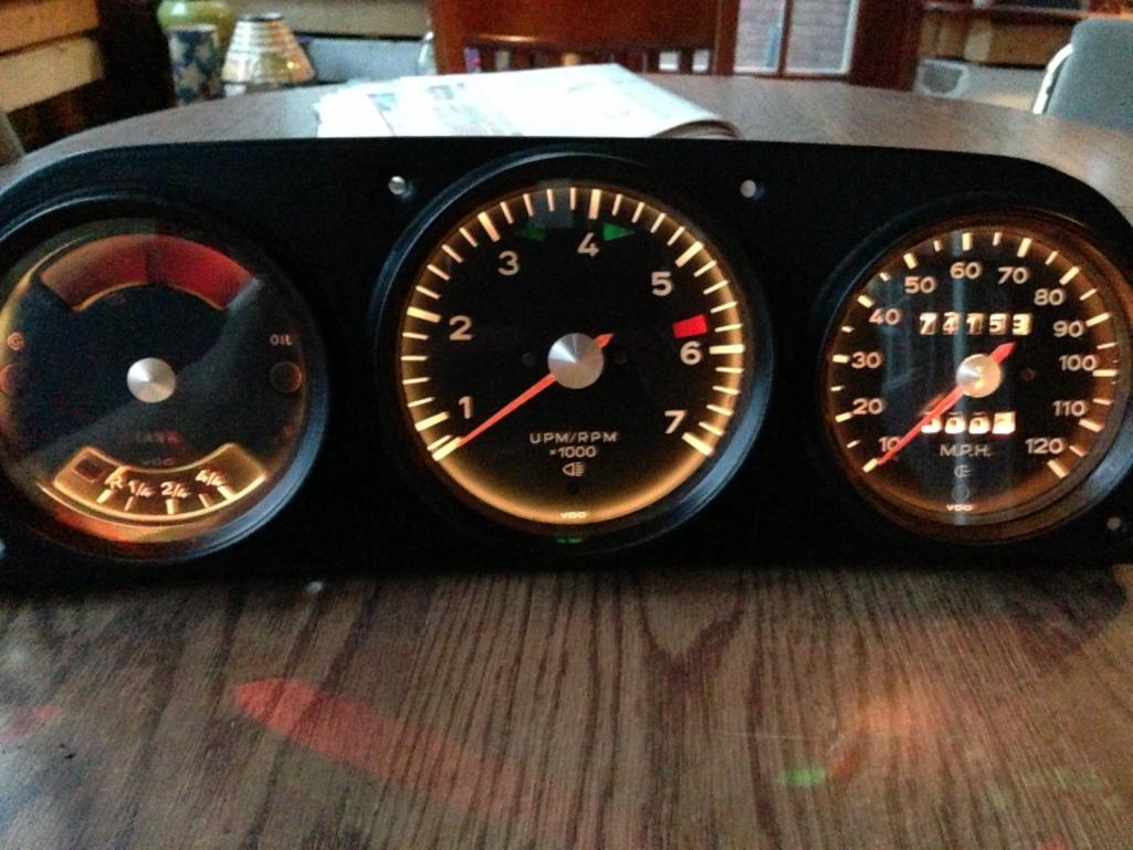 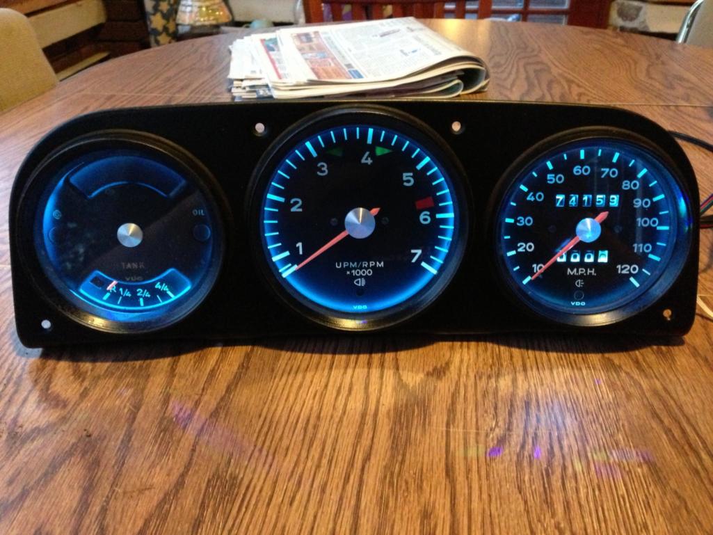 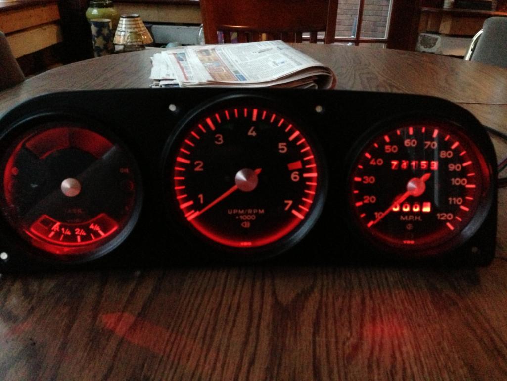 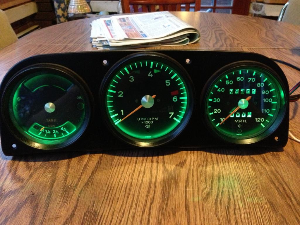 |
|
|
|
| timothy_nd28 |
Jul 2 2013, 04:03 PM
Post
#9
|
|
Advanced Member Group: Members Posts: 2,299 Joined: 25-September 07 From: IN Member No.: 8,154 Region Association: Upper MidWest |
    Totally up to you. Now if you are happy with this, you can call it quits here. The next step is modifying the RGB controller to sense the tachometer pulses and change the background color to yellow or red at certain rpms. This mod if my most favorite part, and I'm quite excited about it. As mentioned before, there will be a special input for low fuel that turn the gauges red when you are low on fuel. Question is, how many of you guys are interested in this idea? I need to know how many circuit boards to make. |
|
|
|
| timothy_nd28 |
Jul 2 2013, 04:03 PM
Post
#10
|
|
Advanced Member Group: Members Posts: 2,299 Joined: 25-September 07 From: IN Member No.: 8,154 Region Association: Upper MidWest |
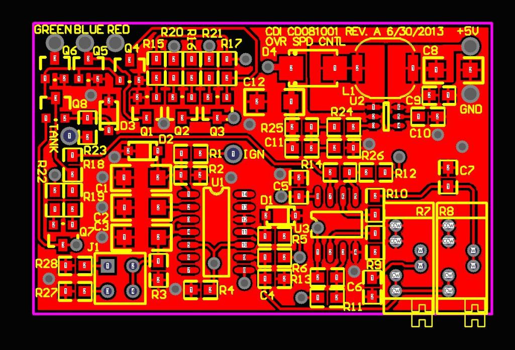
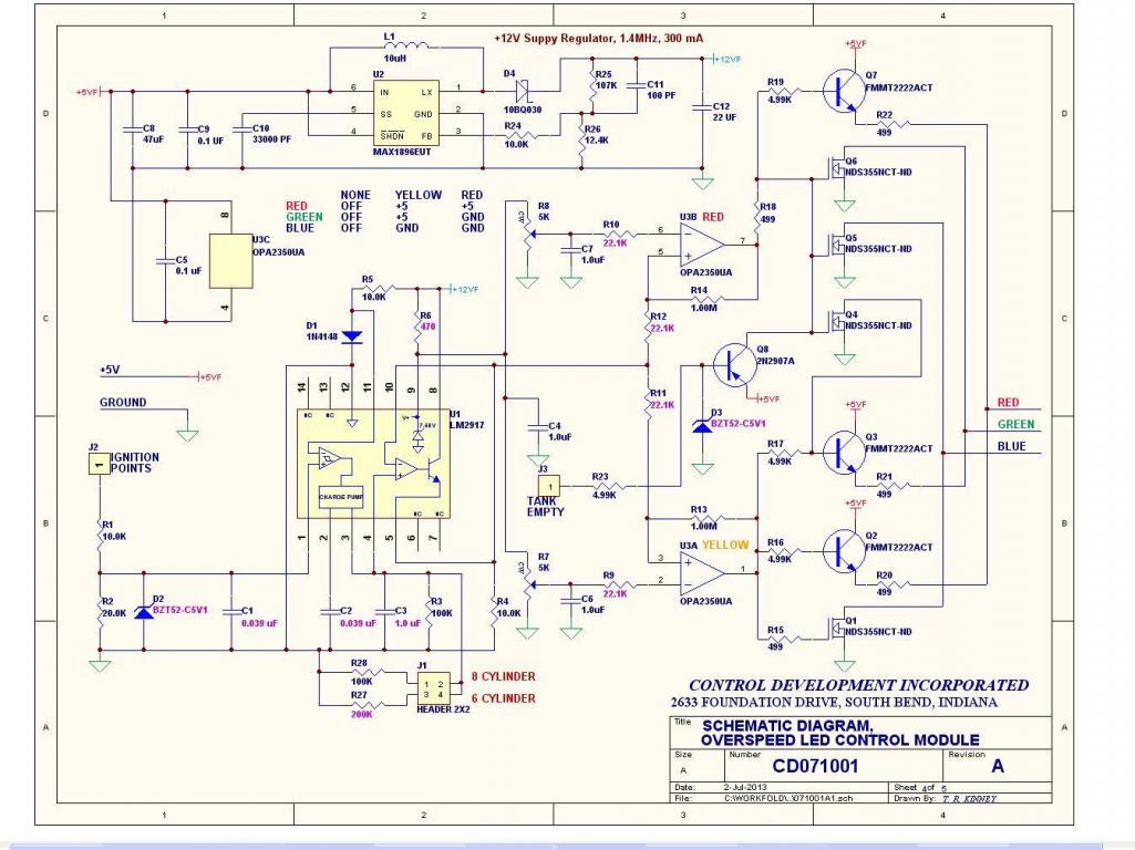
Here is the board artwork for the circuitboard which sets the color to yellow at a set speed and red at another set speed. Also red when the tank empty sensor is engauged.
  |
|
|
|
| montoya 73 2.0 |
Jul 2 2013, 05:54 PM
Post
#11
|
|
Lack of consideration to others, and Selfish! Group: Members Posts: 1,791 Joined: 27-October 04 From: Paso Robles, Ca. Member No.: 3,016 Region Association: Central California |
Nice job (IMG:style_emoticons/default/thumb3d.gif)
This part II thread should also be in the Classics forum! |
|
|
|
| timothy_nd28 |
Jul 2 2013, 06:06 PM
Post
#12
|
|
Advanced Member Group: Members Posts: 2,299 Joined: 25-September 07 From: IN Member No.: 8,154 Region Association: Upper MidWest |
QUOTE(montoya 73 2.0 @ Jul 2 2013, 03:54 PM)  Nice job (IMG:style_emoticons/default/thumb3d.gif) This part II thread should also be in the Classics forum! Thanks (IMG:style_emoticons/default/beerchug.gif) |
|
|
|
| DBCooper |
Jul 2 2013, 08:07 PM
Post
#13
|
|
14's in the 13's with ATTITUDE Group: Members Posts: 3,079 Joined: 25-August 04 From: Dazed and Confused Member No.: 2,618 Region Association: Northern California |
Wow. I guess to be an electronics whiz you need to have really good eyesight, huh? And soldering skills. Very cool. Really like the results. If I could see better I'd be tempted to try that myself.
|
|
|
|
| timothy_nd28 |
Jul 2 2013, 08:24 PM
Post
#14
|
|
Advanced Member Group: Members Posts: 2,299 Joined: 25-September 07 From: IN Member No.: 8,154 Region Association: Upper MidWest |
No eyesight needed, I'm trying to make this as a kit for everyone. This should install into our car without the need of cutting any wires and under one hour. I will also perform this work to your gauge cluster as a service. I just need to know if you guys are interested with this. I need to place an order soon for these circuit boards to be made. It changes the price on my end for ordering one board versus 100 boards.
|
|
|
|
| timothy_nd28 |
Jul 2 2013, 08:48 PM
Post
#15
|
|
Advanced Member Group: Members Posts: 2,299 Joined: 25-September 07 From: IN Member No.: 8,154 Region Association: Upper MidWest |
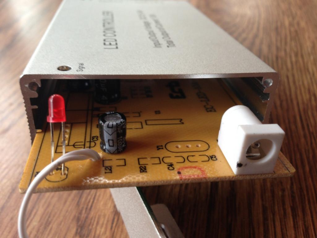
Here is the RGB controller box with its board pulled out slightly. The LED Overspeed Control Module will mount inside of this RGB controller box, so no extra wiring or connectors or boxes. There will be two holes added for the speed setting adjustments and two wires though a grommet hole for the tach and tank connections.
 |
|
|
|
| ThePaintedMan |
Jul 2 2013, 08:50 PM
Post
#16
|
|
Advanced Member Group: Members Posts: 3,885 Joined: 6-September 11 From: St. Petersburg, FL Member No.: 13,527 Region Association: South East States |
Tim, this is cool as Fuchs man. Al would be proud and I think you've got a great thing going. Keep up the great work dude.
|
|
|
|
| timothy_nd28 |
Jul 2 2013, 08:52 PM
Post
#17
|
|
Advanced Member Group: Members Posts: 2,299 Joined: 25-September 07 From: IN Member No.: 8,154 Region Association: Upper MidWest |
QUOTE(ThePaintedMan @ Jul 2 2013, 06:50 PM) Tim, this is cool as Fuchs man. Al would be proud and I think you've got a great thing going. Keep up the great work dude. Thanks man, how many can I put you down for? |
|
|
|
| SirAndy |
Jul 2 2013, 08:56 PM
Post
#18
|
|
Resident German Group: Admin Posts: 41,600 Joined: 21-January 03 From: Oakland, Kalifornia Member No.: 179 Region Association: Northern California |
|
|
|
|
| Mr.242 |
Jul 2 2013, 09:08 PM
Post
#19
|
|
May your glass be smaller so it's always FULL! Group: Members Posts: 1,079 Joined: 10-June 08 From: Seattle Member No.: 9,160 Region Association: Pacific Northwest |
Simply amazing! A cool simple add on to the 40 year old car.
I'm a +1 for a programed board and a kit. I've already bought the basic white light, but the idea to change the color is simple. AND I like the tach and empty tank lighting idea. Can we do one more circuit for an 'overweight' warning on the passenger seat? Thanks! |
|
|
|
| DBCooper |
Jul 2 2013, 09:17 PM
Post
#20
|
|
14's in the 13's with ATTITUDE Group: Members Posts: 3,079 Joined: 25-August 04 From: Dazed and Confused Member No.: 2,618 Region Association: Northern California |
Unfortunately my gauges are all non-stock or I'd be in this for two. Damn.
|
|
|
|
|
1 User(s) are reading this topic (1 Guests and 0 Anonymous Users)
0 Members:

|
Lo-Fi Version | Time is now: 16th April 2024 - 06:21 AM |
Invision Power Board
v9.1.4 © 2024 IPS, Inc.