|
|
|
Porsche, and the Porsche crest are registered trademarks of Dr. Ing. h.c. F. Porsche AG.
This site is not affiliated with Porsche in any way. Its only purpose is to provide an online forum for car enthusiasts. All other trademarks are property of their respective owners. |
|
|

  |

| r3dplanet |
 Jun 10 2015, 04:02 PM Jun 10 2015, 04:02 PM
Post
#141
|
|
Senior Member  Group: Members Posts: 679 Joined: 3-September 05 From: Portland, Oregon Member No.: 4,741 Region Association: None |
Good news, everyone.
In the past week the engine case halves have been returned from the machinist. However, he has yet to return the pistons and cylinders. I have high hopes that those parts will also soon return. In other good news, Tom Knoblauch has produced a pair of beautiful aluminum intakes with custom tapers to perfectly fit the Weber 44 carbs. I'm thrilled with them. Strangely, I'm now in the position of building two motors simultaneously: the 1911 and this Corvair engine. I suppose I need to find a roller with flares for one of them... 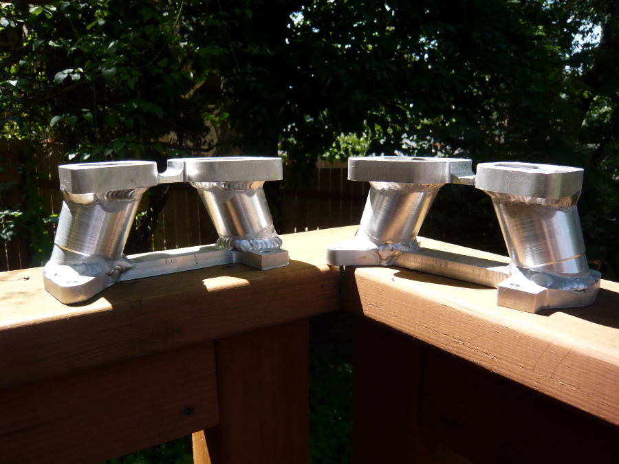 |
   |

 
|
| vw505 |
Aug 16 2015, 05:31 PM
Post
#142
|
|
Member Group: Members Posts: 228 Joined: 17-April 03 From: San Antonio, TX , Navy retired Member No.: 579 Region Association: None |
Nice, I've spoken to Tom a few times and hope to have him do my heads.
|
|
|
|
| r3dplanet |
Aug 17 2015, 02:17 AM
Post
#143
|
|
Senior Member Group: Members Posts: 679 Joined: 3-September 05 From: Portland, Oregon Member No.: 4,741 Region Association: None |
Indeed. I have nothing but praise for Tom. But the machinist who stole my engine parts, not so much.
|
|
|
|
| r3dplanet |
Feb 4 2017, 11:59 PM
Post
#144
|
|
Senior Member Group: Members Posts: 679 Joined: 3-September 05 From: Portland, Oregon Member No.: 4,741 Region Association: None |
People,
I'm pleased to announce that the project is back in motion. It took a very long time to recover from the transplant and I still have complications. But I've been spending my time in night school in a machining program, so that's fun and gives me access to large, fun machines. I've re-purchased all of the parts that I lost and they're on their way to the respective machinists for modification. After those return, it's fun assembly time. That is all. marcus out |
|
|
|
| KELTY360 |
Feb 5 2017, 12:02 AM
Post
#145
|
|
914 Neferati Group: Members Posts: 5,189 Joined: 31-December 05 From: Pt. Townsend, WA Member No.: 5,344 Region Association: Pacific Northwest |
Glad to hear you're back.
|
|
|
|
| JRust |
Feb 5 2017, 12:10 AM
Post
#146
|
|
914 Guru Group: Members Posts: 6,317 Joined: 10-January 03 From: Albany Oregon Member No.: 129 Region Association: Pacific Northwest |
Good to hear things are improving health wise Marcus. Been a while & good to see you back posting (IMG:style_emoticons/default/biggrin.gif)
|
|
|
|
| raynekat |
Feb 5 2017, 03:34 AM
Post
#147
|
|
Advanced Member Group: Members Posts: 2,171 Joined: 30-December 14 From: Coeur d'Alene, Idaho Member No.: 18,263 Region Association: Pacific Northwest |
Marcus:
I'm out here in Boring, so I could always lend you a hand (muscle wise) if you need that from time to time. Fun reading about the Corvair engine project. Good luck with your project. You seem like quite the "mad scientist"? In a good way. (IMG:style_emoticons/default/wink.gif) |
|
|
|
| Dr Evil |
Feb 5 2017, 08:09 AM
Post
#148
|
|
Send me your transmission! Group: Members Posts: 23,044 Joined: 21-November 03 From: Loveland, OH 45140 Member No.: 1,372 Region Association: MidAtlantic Region |
Kick ass!
|
|
|
|
| r3dplanet |
Feb 5 2017, 01:57 PM
Post
#149
|
|
Senior Member Group: Members Posts: 679 Joined: 3-September 05 From: Portland, Oregon Member No.: 4,741 Region Association: None |
Fantastic. Always great to have local friends. And yes, the "mad scientist" type certainly applies. I'm burdened with way too many interests and hobbies. But weirdly, all of them are expensive. Why couldn't I settle for crosswords instead?
It's great to hear from the old gang. I'm glad you guys are all still here. * Some serendipity these past few days: First, Tom Knobluach is wanting to do the exactly same 92mm VW Type 1 cylinder conversion, so he's doing the work for both of us simultaneously. So I bought all the parts and he's doing the machining. Good. I also did some measuring and discovered that on my heads the chamber opening is still the stock Corvair diameter at 96mm. The outer diameter of 92mm VW cylinders is 101.10mm, so Tom is also going to flycut them to the correct size. That's better since he'll have the cylinder in hand to measure. I've seen the slop between these at a build parties off by 2mm. Yikes. Second, another machinist is modifying the case halves to increase the oil passage sizes. The stock passages are a joke and he's got all the rigging to do it right. Weirdly, he has a very similar cancer to mine and he's been out for a while also. So I picked up a new friend. I think it worked out better having to do this part of the operation again after pausing a few years. But what a strange path to get here. I hate to use the term but I think my "qi" is in whack. Anyway, all the parts are shipped off. This week I'm getting the crankshaft nitrided. The crank has already been cryo'd, ground, and polished. It's not a factory nitrided crank like I would have liked, but it's cheap do to and this way the nitriding will not have lost any depth from grinding. -m. QUOTE(raynekat @ Feb 5 2017, 01:34 AM)  Marcus: I'm out here in Boring, so I could always lend you a hand (muscle wise) if you need that from time to time. Fun reading about the Corvair engine project. Good luck with your project. You seem like quite the "mad scientist"? In a good way. (IMG:style_emoticons/default/wink.gif) |
|
|
|
| r3dplanet |
Feb 5 2017, 01:59 PM
Post
#150
|
|
Senior Member Group: Members Posts: 679 Joined: 3-September 05 From: Portland, Oregon Member No.: 4,741 Region Association: None |
Hey, what's the lastest on your Corvair powered bus? Any updates? The last I saw you were sorting out the CIS system.
QUOTE(Dr Evil @ Feb 5 2017, 06:09 AM) Kick ass! |
|
|
|
| r3dplanet |
May 28 2017, 04:40 PM
Post
#151
|
|
Senior Member Group: Members Posts: 679 Joined: 3-September 05 From: Portland, Oregon Member No.: 4,741 Region Association: None |
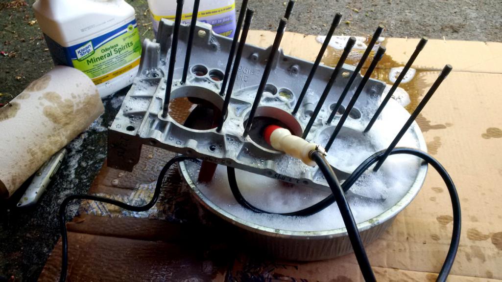
'Twas a pleasant summer's eve so I took the case halves outside for a refreshing douche. This is a makeshift parts cleaner assembled from an oil pan, aquarium pump, and an Oxford comma. Purple Simple Green is used to remove the last of the machining swarf and bits. I wish they would name it "Complicated Purple."
 I received the case halves from Tom Stark a while back for some modification and he did a stellar job. A common problem with the cases is that the depth of the oil passages for the main bearings are too shallow. Indeed, some are so shallow that they're not a passage at all. Add to that that the passages are sometimes misaligned with the bearing holes, creating a blockage. Enter Tom Stark, who has a setup where he uses a mill to widen and deepen the passages. It's a huge improvement for more oil volume. Frankly I don't know how the unmodified passages allowed any oil through them in the first place. Often when I work on this project I repeat the mantra with an inward voice, "GM just did not care." Here you can see the detail of the enlarged oil passage. I'm sorry that I don't have a "before" photo handy. But trust me, the depth was all over the place and it blocked the original bearing oil holes by over half. Another modification is enlarge the oil hole itself that leads to the main oil gallery. 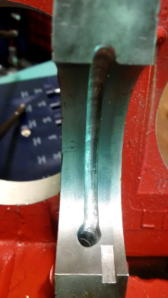 Before I installed the bearings I took some measurements on the inside crank registers. Tom did also but I wouldn't be doing my job if I didn't double check. Besides, this is really all about having fun with arithmetic anyway. 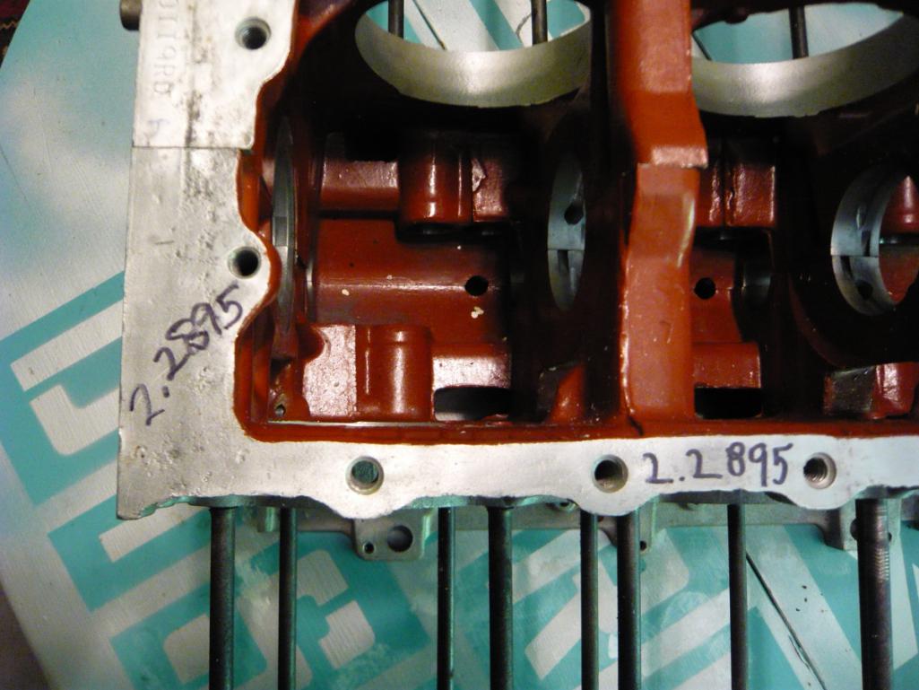 More importantly, I also started the blueprinting process so I took careful measurements of the mains along the crankshaft. 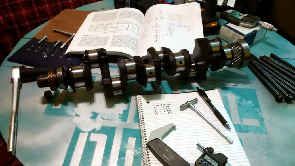 |
|
|
|
| r3dplanet |
May 28 2017, 05:13 PM
Post
#152
|
|
Senior Member Group: Members Posts: 679 Joined: 3-September 05 From: Portland, Oregon Member No.: 4,741 Region Association: None |
Time to check the bearing clearance and oil passage holes.
The bearings themselves are Clevite 77. For mains #2 and #3 the bearings are the same. But somewhere along the way GM changed the size for #4. Bob Helt says this has to do with a lumpy idle problem encountered before the change. Observe: 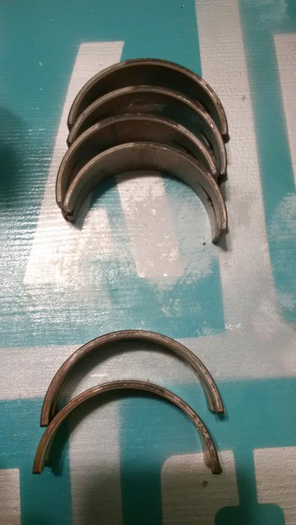 Here you can see how well the diameter of the oil hole in the bearing meets the enlarged oil passage. Helloooo oil volume: 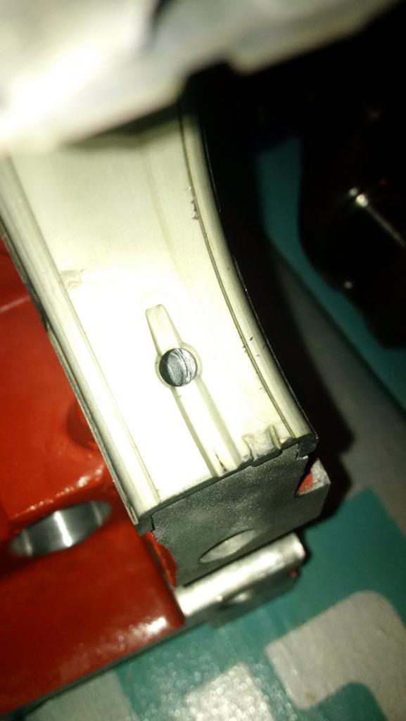 Here are the bearings installed in the case halves: 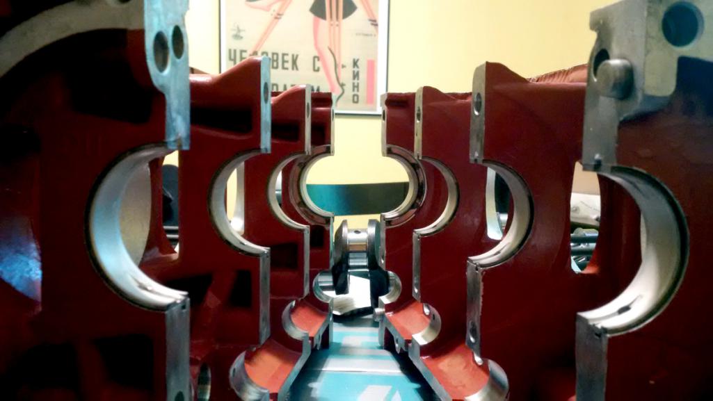 I torqued the case halves back together to measure the inner diameter of the bearings. And, unhappily, they all measured about 0.010" too large. Bummer. This troubled me for a while because way way back I had a machinist check out the case, bearings, and crankshaft to make sure they were all in spec. So where did this 0.010" difference come from? Then I finally remembered. I have two crankshafts and completely forgot that I had two cranks because (a) I'm chemo-brained and (b) it's been a long, long time. I forgot that initially I had the original crank measured, magnafluxed, ground, and polished to 0.010" undersize. Then I sent it off to be cryogenically treated. But over the years enough doubt was cast on the cryo process that I replaced it with a factory nitrided crank. It's important to understand that the better Corvair cranks were nitrided from the factory, but my original crank was not as discussed in a previous post. So eventually I bought a NOS nitrided crank thinking it was the better surface hardening method over cryo. But the fact is that I really do not know. It's been debated so much that I honestly don't know which would better fit my needs, which mainly have to do with longevity. But now I have two great cranks with absolutely no way of truly knowing which is better. It's apples and oranges most likely. Nitriding is a suface hardening process and cryo is a process to remove any internal stress and improve it's overall toughness. Oy. Anyway, here they are: 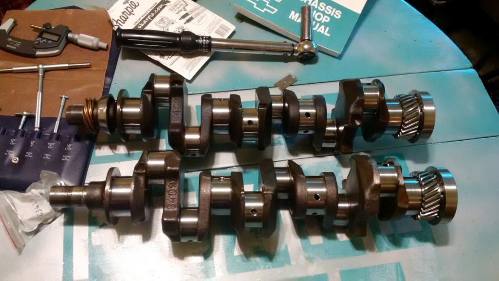 So my choice is to either use the cryo'd crankshaft and use the bearings I already have, or use the nitrided crank and order two new sets of bearings. One pisser is that you cannot buy individual bearings. You have to buy a complete set. And it turns out the big shell bearing for main #1 is not out 0.010" but 0.0065". So if I buy new bearings I have to buy two whole sets to get the sizes that I need. Super! Either way I have one great crankshaft for sale. I'm open to which way I should go if anyone knowledgeable about metallurgy cares to opine. Cheers. |
|
|
|
| r3dplanet |
May 29 2017, 11:13 PM
Post
#153
|
|
Senior Member Group: Members Posts: 679 Joined: 3-September 05 From: Portland, Oregon Member No.: 4,741 Region Association: None |
Today I spent some time getting the rest of the measurements for the bottom end.
The camshaft got the plastigauge treatment and it's dead nuts 0.002" clearance across the board. The service manual says it needs to be between 0.0015" to 0.0035", so that makes me happy. I measured the ID of the big ends of the piston rods and that's where this gets interesting. And by interesting I mean super boring. With the bearings I have in hand they're a perfect fit for the rod journals which measures 0.010" undersize from standard. No problem there since one of my two cranks measures 0.010" undersize... .... the crogenically treated one. So that's the answer to above soliloquy. If I stay with the cryo'd crankshaft, then I can keep my main bearings, rods, and rod bearings. The rods have already been machined to fit the VW piston pins. That's a pile of money and time I don't want to spend in replacing stuff. Plus, the measurements for the crank and rods have been beautiful so far. I sort of hate to throw all that out since it all fits together so sweetly. Plus, science. It occurred to me today maybe instead of looking for an answer to cryo vs nitriding I should instead pop in the cryo'd crankshaft and see what happens. At worst it will simply wear down faster. It's not like it's just going to split apart. So one day when one of you owns this car and takes the engine apart, do us all a favor and measure the wear along the journals and note the mileage. That way we can all know. Of course it isn't great science since I'm not building an identical engine using the nitrided crank, but there's enough data out there to get a comparison. Empiricism or bias confirmation? You decide. If you in the future are the owner of this car and have disassembled the engine then you'll want to know that the main journals measure basically 2.0985" and the rod journals more or less at 1.9327". Good luck, time traveler! |
|
|
|
| r3dplanet |
Jun 25 2017, 02:11 PM
Post
#154
|
|
Senior Member Group: Members Posts: 679 Joined: 3-September 05 From: Portland, Oregon Member No.: 4,741 Region Association: None |
So I damn near ruined my case halves.
There are eight (8x) case studs that clamp the case halves together, but they are a slop fit and allow the halves to slide around a little at higher temps and revs. So for a long time ARP case studs have been available that have a larger diameter in order to create an interference fit. Great. The trouble is that outfits like Clark's or others-that-shall-not-be-named will sell or rent a reamer that provides the exact diameter necessary to make the correct fit. But Clark's doesn't have them any more and other vendors failed to even mail me back and didn't answer the phone. Since I couldn't obtain the "special" reamer, I had to try something else. My first plan was to get an adjustable reamer, which I hate. I've never had good luck with them. I ended up buying a few of them before I found one that was even marginal quality. Even with my measuring stand it's hard to set the tool to exactly the right size. Every time the tool is set and tightened, it threw out my measurement. I drilled the first hole to a depth of about 5mm and then measured the new bore.. and it was way WAY out of size. Not a big deal since there was so much meat left, but I wasn't happy. So I spent a few hours with a piece of scrap aluminum sneaking up on the bore size, but it left a positively brutal finish. I didn't think the adjustable reamer would last for all sixteen holes and the finish was unacceptable, so I went to Plan B. The dimension in question is the outer diameter of the case studs at the center bulge, measuring 15/32" (0.4688"). I ended up using a 29/64" drill bit (0.4531") and then using the reamer. It's the best match I could find but hand reaming .016" sucks, especially when it's sixteen holes. 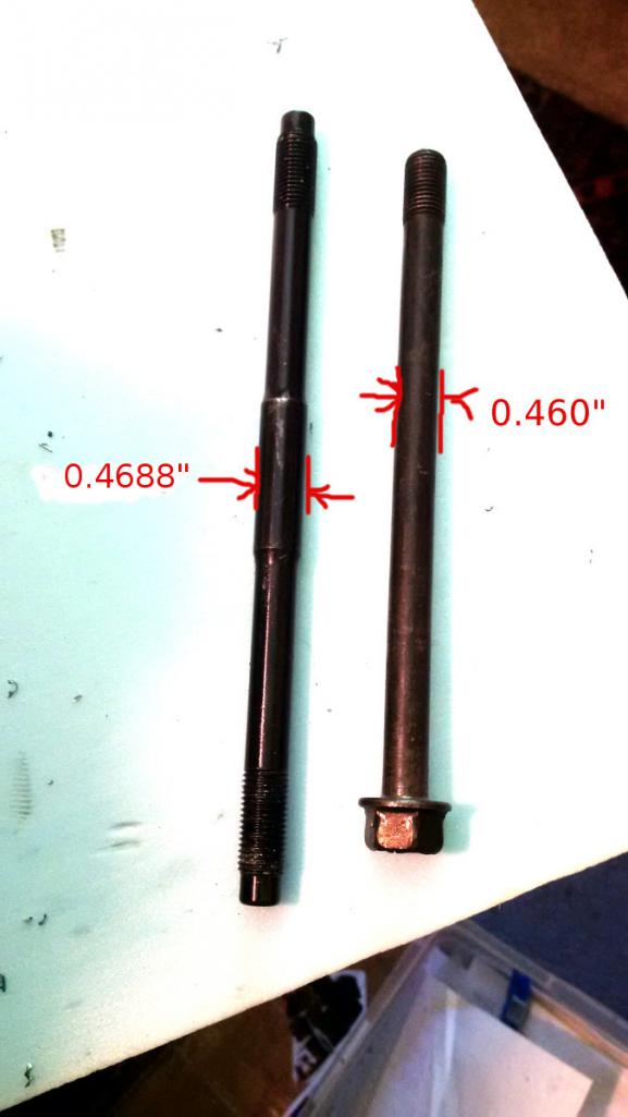 On the right side of the engine the bore is increased all the way through. On the left side of the engine the bore is only increased about an inch to give the studs someplace to seat. I'm not super happy about the outcome, but it will work and the fit is quite good. But I worry about what might happen if any of the mating bores are a little off. It makes for white knuckles. Anyway, all of the prep is now done. Now I need to thoroughly clean out the engine halves again and it's time for assembly. FINALLY. 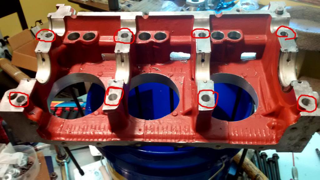 |
|
|
|
| r3dplanet |
Jun 25 2017, 06:54 PM
Post
#155
|
|
Senior Member Group: Members Posts: 679 Joined: 3-September 05 From: Portland, Oregon Member No.: 4,741 Region Association: None |
Alright...
It's 102 degrees (39c) outside so I hosed myself down with the garden hose and pulled out my bucket-based parts washer. I very thoroughly and very carefully washed out both case halves, blasted them with clean water, and then with compressed air and set them out to dry. No problem on a horrible day like this. So let's start the assembly. Before cleaning it, I pulled and numbered each of the main bearings. After cleaning the cases I cleaned the bearings with mineral spirits, popped them into place, and smeared on some good synthetic assembly lube. 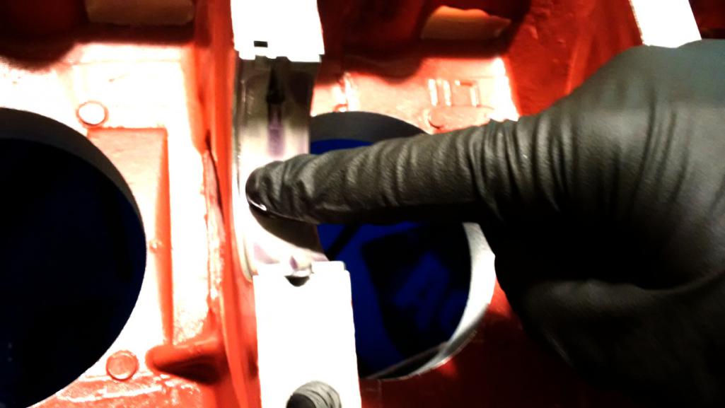 I cleaned the crank with the nastiest residue-free cleaner I had (Berkebile 2+2) and made very sure it was as clean as I could get it and that no remnants of plastigauge were left behind. The crank popped into place and rotates as smooth as can be. 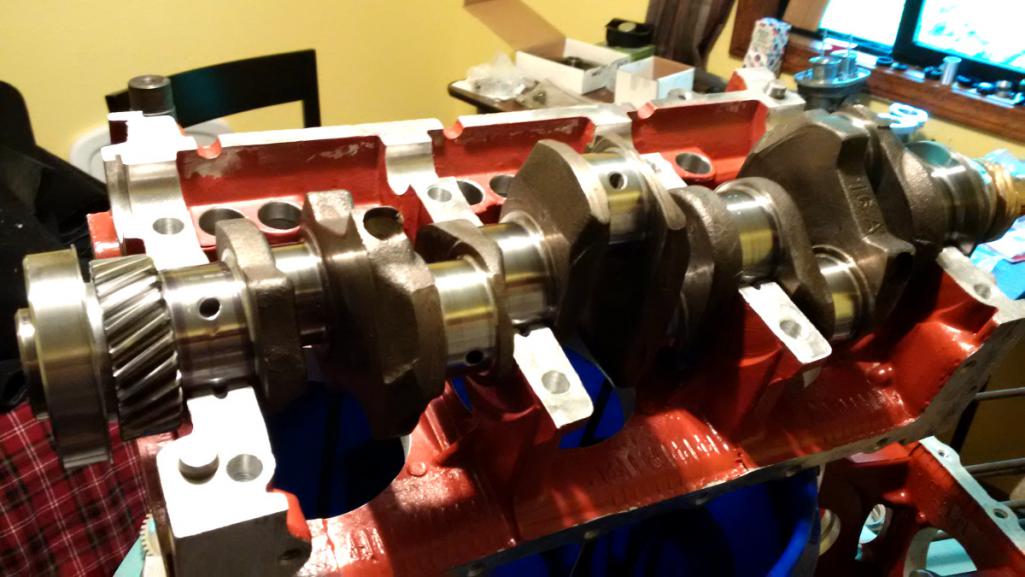 Here is the timing mark on the crank. It's remarkably small and barely looks like it was deliberately placed. I drew some reference lines with a marker to verify it's position in relation to the mark on the camshaft. 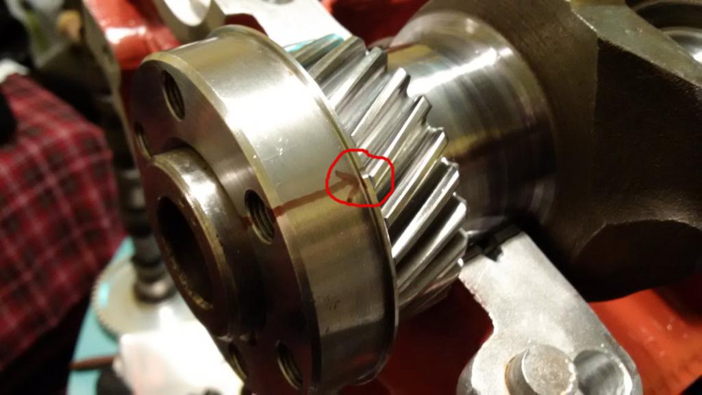 I couldn't photograph and install the cam at the same time, but it's the same procedure as an air cooled VW. Line up the marks and walk the cam into it's home. In this photo you can look into the bolt hole of the crank gear and see that my sharpie-based cam and crank marks line up correctly. 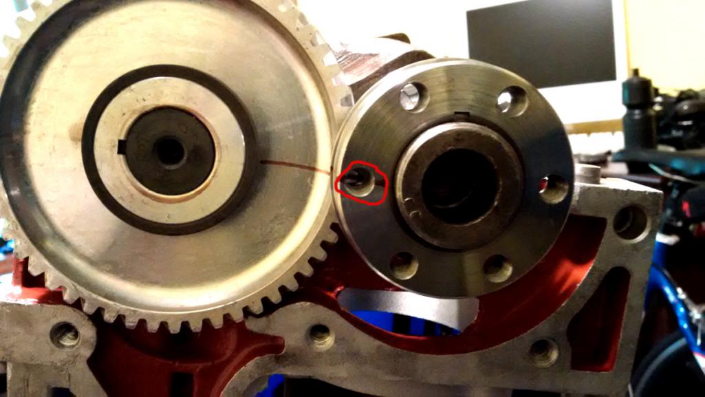 Here they are together in the case. 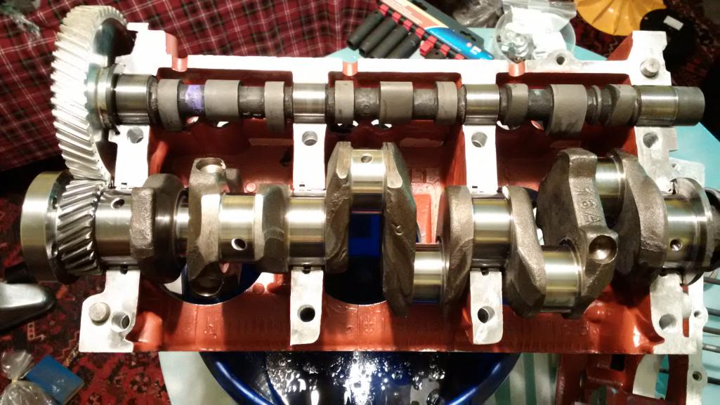 And then I clean, install, and lube the opposite main bearings and camshaft and mate the other case half. I bolted the case halves together with the OLD case bolts because I want to make sure it continues to freely spin as I torque down the nuts. I'll have to separate them once last time to smear on some Yamabond or or something. But first I want to degree the cam and then verify end play. 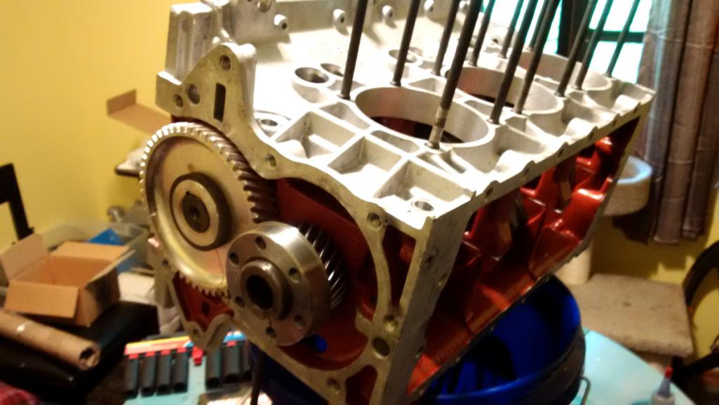 The factory service manual says to measure crankshaft end play and make sure it's between .002-.006". You can see here that mine is at .004". That's a relief. 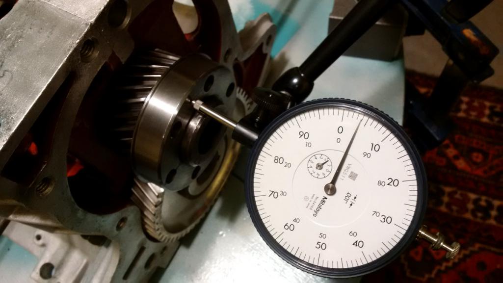 The next step is to degree the cam. It's next to impossible for this particular cam to be that far out of whack, and if it is I'll need to use an offset Woodruff key, which means pulling it all apart again. I hope that doesn't happen. Mostly I just want to verify the cam/crank timing. In the meantime I think I need to buy an adapter so I can connect a degree wheel. More soon. |
|
|
|
| r3dplanet |
Jul 2 2017, 03:14 AM
Post
#156
|
|
Senior Member Group: Members Posts: 679 Joined: 3-September 05 From: Portland, Oregon Member No.: 4,741 Region Association: None |
Sooooooo let's degree this thing and make sure I didn't install the camshaft off by a tooth or something stupid. I like sanity checks. Here's the situation as of a few hours ago. I installed rings onto one of the pistons (more on this later) and then the piston into cylinder #1. Then I made a high quality genuine Red Planet Industries piston stop.
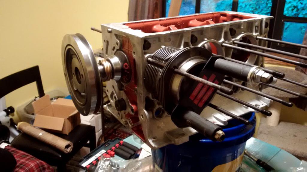 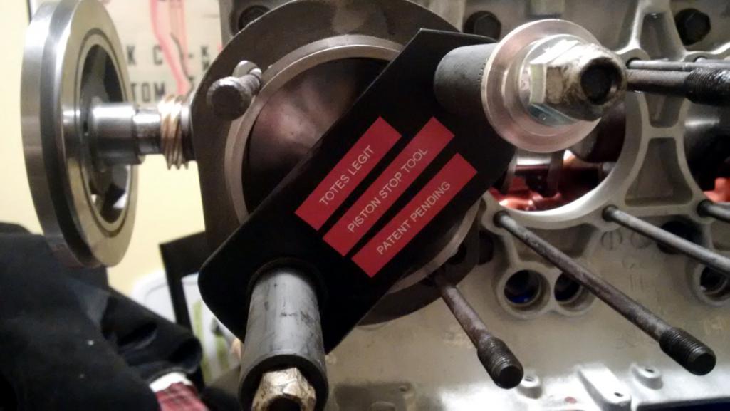 I've been following a Corvair aircraft engine build by a cat named Mark Langford, and he has a good write up on degree-ing the cam. He even provides a nice template to use with the existing crank pulley. Here's the link: http://www.n56ml.com/corvair/degree_cam.html The idea is to use the piston stop to find actual TDC for this engine. Install the high quality piston stop, rotate the engine one way and until it stops and use the centerline of the case to mark the pulley. Then rotate the other way until it stops and make another mark. In between both marks is actual TDC. (Full disclosure, I also removed the high quality piston stop and rigged up a dial micrometer). 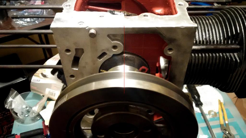 It turns out that it's very nearly dead nuts accurate. I was more than surprised. 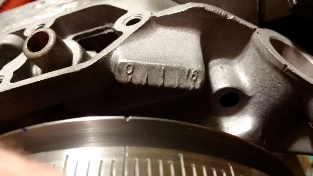 Here's Mark Langford's template taped to the pulley. I failed to get any clear photos of the dial indicator gauge on the intake and exhaust lifters. Oh well. This is already super boring for everyone but me. 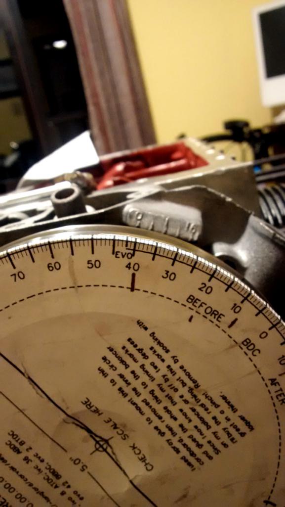 So finally I ended up with the following numbers. Basically there's no place where my cam deviates by more than one degree, so I'm very very happy indeed. Intake at .005" Card Me Open 25 24 Close 65 64 Intake at .050" Card Me Open 1 2 Close 35 34 Exhaust at .005" Card Me Open 72 72 Close 32 33 Exhaust at .050" Card Me Open 42 42 Close 8 7 Huzzah! |
|
|
|
| PatrickB |
Jul 2 2017, 05:36 AM
Post
#157
|
|
Member Group: Members Posts: 249 Joined: 26-March 17 From: sw ontario Member No.: 20,960 Region Association: Canada |
QUOTE(mgp4591 @ Jan 6 2015, 12:28 AM) Just a quick question as I'm clueless- what year 'Cuda so I can drool some more?! That was a '65 I saw in a pic back there, prefer the '66 myself. |
|
|
|
| Porschef |
Jul 2 2017, 06:34 AM
Post
#158
|
|
How you doin' Group: Members Posts: 2,180 Joined: 7-September 10 From: LawnGuyland Member No.: 12,152 Region Association: North East States |
'Tain't boring a'tall, not that I know exactly what you're doing...
Impressive nonetheless. As well as your constitution. (IMG:style_emoticons/default/beerchug.gif) |
|
|
|
| r3dplanet |
Jul 2 2017, 12:12 PM
Post
#159
|
|
Senior Member Group: Members Posts: 679 Joined: 3-September 05 From: Portland, Oregon Member No.: 4,741 Region Association: None |
Oh right, yes my Barracuda is a '65. It's virtually all new underneath. New 360ci engine, gearbox, disc brakes, larger clutch / bell housing, driveline, 8-3/4" rear end, new interior, re-upholstered everything, hydroboost p/s and p/b, hydraulic clutch, headers, a million other things. I found a painter in town that I really like so I'm thinking about finally getting it painted. Or maybe I'll sell it. The Barracuda is a gentleman's cruiser, not a hot rod. A true GT car. I'll decide what to do with it and the end of the year. All I do is work on it. I almost never drive it. But that's starting to change finally. But I might sell it because I have yet another project - a Beetle. Long story. More on that later.
The '66 and '65 are nearly the same car. The '66 had some cosmetic differences and a slightly different gauge cluster. And some little differences in the 273ci engine. Both are very cool though. I hardly ever see them around any more. Seriously - after I sell off all this stuff I'm dedicating my life to cheap hobbies. QUOTE(PatrickB @ Jul 2 2017, 04:36 AM) QUOTE(mgp4591 @ Jan 6 2015, 12:28 AM) Just a quick question as I'm clueless- what year 'Cuda so I can drool some more?! That was a '65 I saw in a pic back there, prefer the '66 myself. |
|
|
|
| barefoot |
Jul 2 2017, 02:34 PM
Post
#160
|
|
Senior Member Group: Members Posts: 1,517 Joined: 19-March 13 From: Charleston SC Member No.: 15,673 Region Association: South East States |
[quote name='r3dplanet' date='Jul 2 2017, 05:14 AM' post='2502276']
Sooooooo let's degree this thing and make sure I didn't install the camshaft off by a tooth or something stupid. I like sanity checks. Here's the situation as of a few hours ago. I installed rings onto one of the pistons (more on this later) and then the piston into cylinder #1. Then I made a high quality genuine Red Planet Industries piston stop. I did essentially the same thing using a spark plug modified by knocking out the ceramic & ground electrode and welding in a longer stub that would contact the piston somewhat before TDC. rotating to this stop one way, then the other nailed TDC exactly |
|
|
|
|
5 User(s) are reading this topic (5 Guests and 0 Anonymous Users)
0 Members:

|
Lo-Fi Version | Time is now: 15th June 2026 - 04:37 PM |
Invision Power Board
v9.1.4 © 2026 IPS, Inc.