|
|
|
Porsche, and the Porsche crest are registered trademarks of Dr. Ing. h.c. F. Porsche AG.
This site is not affiliated with Porsche in any way. Its only purpose is to provide an online forum for car enthusiasts. All other trademarks are property of their respective owners. |
|
|

  |

| McMark |
 Dec 10 2004, 01:35 AM Dec 10 2004, 01:35 AM
Post
#21
|
|
914 Freak!  Group: Retired Admin Posts: 20,180 Joined: 13-March 03 From: Grand Rapids, MI Member No.: 419 Region Association: None |
After thinking about this for awhile, I'll have to call it Far-To-Complicated-For-Not-Enough-Payback. I wouldn't be surprised if there was a performance hit because of the D-Jet being "tuned" to the advance curve of the stock distributor. I say, if you're gonna switch something out, get a KitCarlson and have fuel and ignition in one unit. I like you're thinking on this one, but it's time to start engineering something different. If you want some ideas of stuff to engineer, let me know. I've got 8-10 crazy ideas that I'd love to get some help on. (IMG:style_emoticons/default/wink.gif)
|
   |

 
|
| DNHunt |
Dec 10 2004, 07:57 AM
Post
#22
|
|
914 Wizard? No way. I got too much to learn. Group: Members Posts: 4,099 Joined: 21-April 03 From: Gig Harbor, WA Member No.: 598 |
Mike
It looks to me like you need to find the right end of the mule. Drive the car with the D-jet and trigger points of change the FI and ignition. Enjoy the car while you get your MS going. Then swap the to the Mallory and MS. If it takes a year you still have a car you can drive. Dave |
|
|
|
| scotty914 |
Dec 10 2004, 08:47 AM
Post
#23
|
|
suby torque rules Group: Members Posts: 1,528 Joined: 20-July 03 From: maryland, the land of 25 year Member No.: 924 |
QUOTE(McMark @ Dec 9 2004, 11:35 PM) I wouldn't be surprised if there was a performance hit because of the D-Jet being "tuned" to the advance curve of the stock distributor. i dont think the trigger points are tied to the advance plate, i could be wrong because i dream in ljet |
|
|
|
| mikerose |
Dec 10 2004, 10:05 AM
Post
#24
|
|
Happy to be back Group: Members Posts: 657 Joined: 31-December 02 From: Pittsburg,ca Member No.: 60 Region Association: None |
Hi Mike, This is were I say :finger2: :finger2: DO NOT MESS WITH THIS CAR! :finger2:
Just drive it. Mike |
|
|
|
| McMark |
Dec 10 2004, 01:25 PM
Post
#25
|
|
914 Freak! Group: Retired Admin Posts: 20,180 Joined: 13-March 03 From: Grand Rapids, MI Member No.: 419 Region Association: None |
QUOTE(scott thacher @ Dec 10 2004, 06:47 AM) QUOTE(McMark @ Dec 9 2004, 11:35 PM) I wouldn't be surprised if there was a performance hit because of the D-Jet being "tuned" to the advance curve of the stock distributor. i dont think the trigger points are tied to the advance plate, i could be wrong because i dream in ljet I'm not saying the advance is tied to the trigger points. I'm no even talking about the trigger points. To put it differently, what happens to D-Jet when you drastically change the advance curve? Do you then have to screw with the MPS to retune it? I would bet you would have to if you wanted to actually make more power. |
|
|
|
| Mueller |
Dec 10 2004, 11:58 PM
Post
#26
|
|
914 Freak! Group: Members Posts: 17,155 Joined: 4-January 03 From: Antioch, CA Member No.: 87 Region Association: None |
1st off...my car is still running and I have not mechanically molested anything (IMG:style_emoticons/default/smile.gif)
Brad, do you have a BOM for the ECU schematics that are on your website?? D-Jet ECU schematic...information overload...I \"like\" it (IMG:style_emoticons/default/smile.gif) |
|
|
|
| Mueller |
Dec 11 2004, 12:48 AM
Post
#27
|
|
914 Freak! Group: Members Posts: 17,155 Joined: 4-January 03 From: Antioch, CA Member No.: 87 Region Association: None |
another question for you EE types:
what happens if I supply a clean sqaure wave signal to a debounce circut? will it work or will the debounce circut be looking for a ripple? |
|
|
|
| lapuwali |
Dec 11 2004, 02:22 AM
Post
#28
|
|
Not another one! Group: Benefactors Posts: 4,526 Joined: 1-March 04 From: San Mateo, CA Member No.: 1,743 |
You'll get a square wave with a delay. A debounce circuit will look for an "on" signal (pulled high) for some period of time before generating a square wave out. The idea is that a mechanical switch will have noise and the beginning and end of the signal (and maybe in the middle, too). Said noise may pull the signal all the way below whatever you're considering a threshold for "off" or "low" (often well above 0v), which can look like two pulses instead of one. By delaying across the likely time for this transition, it will only "see" one pulse, and only send one pulse out.
The length of time is the crucial bit. For a human-operated switch, this can easily be several milliseconds, since two deliberate up/down/up/down cycles will nearly always take 100ms or thereabouts. Humans are slow. For mechanical points, the bounce time will depend on the max engine speed. For a four-cylinder running at 10K rpm, you'll get a pulse every 1.5ms, so the debouce delay needs to be short, probably around 0.5ms for something with loose timing requirements like injection, but a lot shorter (like 0.001ms!) for ignition if you don't want to skew timing by more than a degree or so and be able to run at high revs. A digital switch, like a Hall-effect, optical, or VR sensor, won't need debouncing. These should generate a nice, clean waveform (sine or sine-like for VR). |
|
|
|
| Mueller |
Dec 11 2004, 03:54 PM
Post
#29
|
|
914 Freak! Group: Members Posts: 17,155 Joined: 4-January 03 From: Antioch, CA Member No.: 87 Region Association: None |
the stock ECU has a debouncing circut that the contacts feed into...so it would seem like I'd need to go from digital (the dizzy) to analog (to mimic the "dirty" signal of the contacts) unless a digital signal can be made to "fake" it...
|
|
|
|
| McMark |
Dec 11 2004, 06:20 PM
Post
#30
|
|
914 Freak! Group: Retired Admin Posts: 20,180 Joined: 13-March 03 From: Grand Rapids, MI Member No.: 419 Region Association: None |
This maybe be stupid or brilliant. Can you somehow "record" the waveform and "play" it back synced with the tach signal?
|
|
|
|
| Mueller |
Dec 27 2004, 11:06 AM
Post
#31
|
|
914 Freak! Group: Members Posts: 17,155 Joined: 4-January 03 From: Antioch, CA Member No.: 87 Region Association: None |
okay you EE types out there.....
want to check out this circuit? Attached image(s) 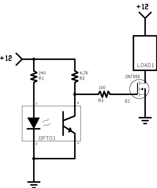
|
|
|
|
| Mueller |
Dec 27 2004, 11:18 AM
Post
#32
|
|
914 Freak! Group: Members Posts: 17,155 Joined: 4-January 03 From: Antioch, CA Member No.: 87 Region Association: None |
There will be 2 opto's each with a "Load1" going to Pin 21 and Pin 22 of the ECU to trigger the injectors.......
|
|
|
|
| lapuwali |
Dec 27 2004, 02:25 PM
Post
#33
|
|
Not another one! Group: Benefactors Posts: 4,526 Joined: 1-March 04 From: San Mateo, CA Member No.: 1,743 |
The opto isn't useful in that circuit. It's not isolating Q1 from anything coming down the left-hand +12.
I assume the left-hand +12 is some sort of switch signal you expect to be nasty, and the upper +12 is constant power. If so, then run the collector of the opto's transistor to the constant +12 up top. Be sure the opto's ground is run back to the ground shared by the nasty signal generator, whatever that is. The idea behind an opto is you have a clean power source and a nasty switching signal. The signal goes on the LED side, and the clean power source on the transistor side. The signal switches the clean power on and off, so you get clean power "out", to the thing you're isolating. As drawn, you'll get the left-hand +12 running straight to Q1, using whatever ground potential exists between Q1 and the switch signal. The opto might as well not be there at all. What's to the left of this circuit? |
|
|
|
| Mueller |
Dec 27 2004, 02:36 PM
Post
#34
|
||
|
914 Freak! Group: Members Posts: 17,155 Joined: 4-January 03 From: Antioch, CA Member No.: 87 Region Association: None |
this circuit was posted on an electronics forum....I asked a question and this is what was replied...totally clueless whether it would work or not (IMG:http://www.914world.com/bbs2/html/emoticons/wacko.gif)
Left hand +12 is from the vehicle power source (ignition activated to turn on) Here is the typed response along with the circuit:
|
||
|
|
|
||
| lapuwali |
Dec 27 2004, 03:11 PM
Post
#35
|
|
Not another one! Group: Benefactors Posts: 4,526 Joined: 1-March 04 From: San Mateo, CA Member No.: 1,743 |
OK, I understand the explanation, but not the circuit, still. If both +12 inputs are constant power, then where does the "interruption" come from? If this isn't an optocoupler (aka optoisolator), but an optical sensor with a shutter between the LED and the transistor, then it all makes sense.
|
|
|
|
| 914GT |
Dec 27 2004, 06:42 PM
Post
#36
|
|
Senior Member Group: Members Posts: 1,101 Joined: 11-October 04 From: Tucson Member No.: 2,923 Region Association: Southwest Region |
The OPTO1 would be either a reflective or transmissive optical switch or interrupter module. These are an LED and phototransistor pair in a plastic case, and the light beam is either interrupted with a slotted disk or similar device on the rotating shaft, or small reflectors on the rotating shaft bounce the light beam from the LED into the phototransistor. It wouldn't make sense to use an optoisolator, these are used to couple signals between two electrical circuits with different ground references.
The circuit would work, whoever posted is just saying that other power N-channel FETs would work, it doesn't have to be that exact one. The LED needs to have 50 mA current but the spec sheet for the part would tell you how much current. You pick a resistor value to give you the right current in the transistor. Use the biggest value to allow the FET to turn off and to keep the power dissipation down. The spec sheet will call out the optimum phototransistor current. Here's a spec sheet for an example optical switch. |
|
|
|
| Mueller |
Dec 27 2004, 09:19 PM
Post
#37
|
|
914 Freak! Group: Members Posts: 17,155 Joined: 4-January 03 From: Antioch, CA Member No.: 87 Region Association: None |
Just tested the circuit on my workbench...it works with the following components:
Optical Interrupter Switch and FET only reason I used these is that we happened to have these sitting in a draw...we used to stock more, but we sold off most of the small components since we don't buildup PCBs anymore....time to do some more research and start ordering parts.... |
|
|
|
| Mueller |
Dec 27 2004, 09:21 PM
Post
#38
|
|
914 Freak! Group: Members Posts: 17,155 Joined: 4-January 03 From: Antioch, CA Member No.: 87 Region Association: None |
I need to add:
the circuit works as is, I have NO idea if it'll trigger the ECU and ground pins 22 and 23 as needed.... |
|
|
|
|
1 User(s) are reading this topic (1 Guests and 0 Anonymous Users)
0 Members:

|
Lo-Fi Version | Time is now: 16th July 2025 - 11:02 PM |
Invision Power Board
v9.1.4 © 2025 IPS, Inc.