|
|
|
Porsche, and the Porsche crest are registered trademarks of Dr. Ing. h.c. F. Porsche AG.
This site is not affiliated with Porsche in any way. Its only purpose is to provide an online forum for car enthusiasts. All other trademarks are property of their respective owners. |
|
|

  |

| worn |
 Sep 9 2013, 09:33 AM Sep 9 2013, 09:33 AM
Post
#1
|
|
can't remember  Group: Members Posts: 3,156 Joined: 3-June 11 From: Madison, WI Member No.: 13,152 Region Association: Upper MidWest |
I thought I would show a few pics of the tool set I made to overcome the MPS tuning. Note I started with an inductance gauge and vacuum line to make graphs of the changes induced by vacuum. This served as baseline out of the car. Then when the car was running I used these with the MPS in place:
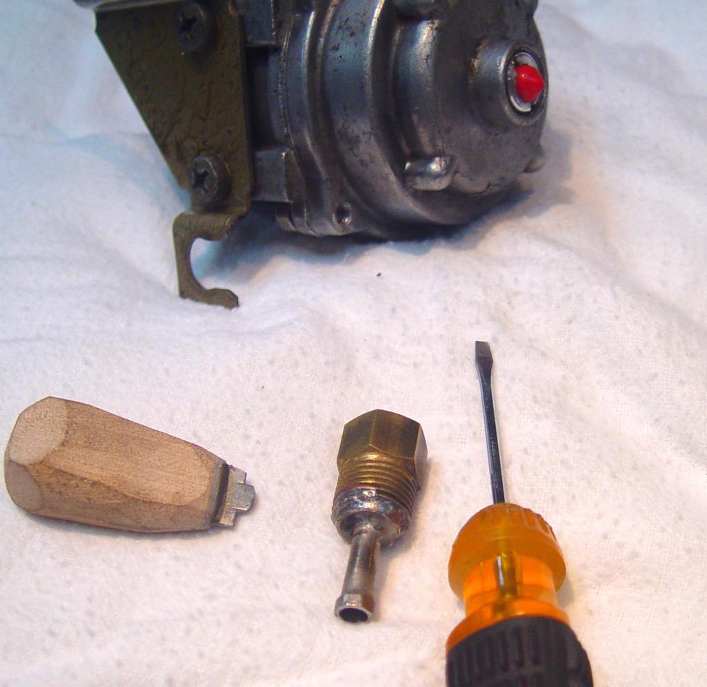 The kit has three pieces, plus an MPS mod through the cap (red plug). First there is a small screw driver for the main adjustment screw that alters rich vs lean. Second is a 7 mm nut ground to fit ito the hex of the aluminum diaphragm adjuster stop. The nut is soldered to a tube and a plumbing piece as a handle (I used stainless steel braze -orange$). The nut is drilled out to allow the screw driver access to the screw. Finally a scrap of 18 ga steel in a wood handle for the cap screw that adjusts where WOT ends up. There is a red plug in the aluminum cap. The cap has been drilled as can be seen here: 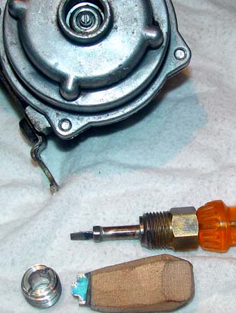 The shoulder is still on the plug, and in this MPS the hole does not make an air leak. It would be air tight with the simpler versions on Ca '69 type 3 and 4 models. Here is a shot showing the hex end and the screw inside it. Sort of like valve adjusters. 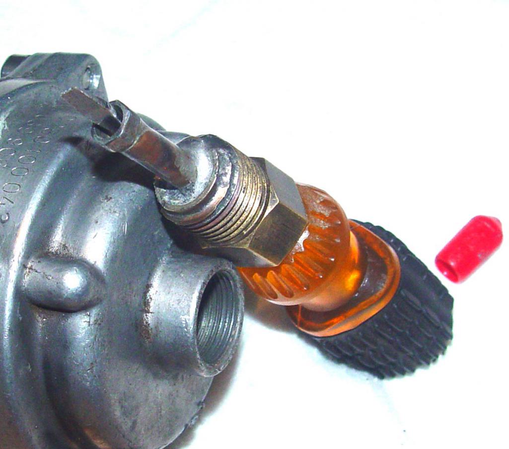 And here we go. Normally this would be a hot engine bay. It is important to have all three screws right, but I used the outer plug and the inner screw had the most impact. I found it very helpful to be able to make adjustments without disturbing the outer stop, so I needed to have a hole through it so any of the three screws can be moved without moving one of the others, and also in short increments as you pull over and try to find the right setting. You want to seat the hex first and then find the slot for the screw driver. I tried to make it so I could turn the small screw while holding the aluminum one still. I just bought a non-working type 3/4 on ebay without the secondary diaphragm that Racer Chris sells (thanks!). It can be fixed and I will give it a try. 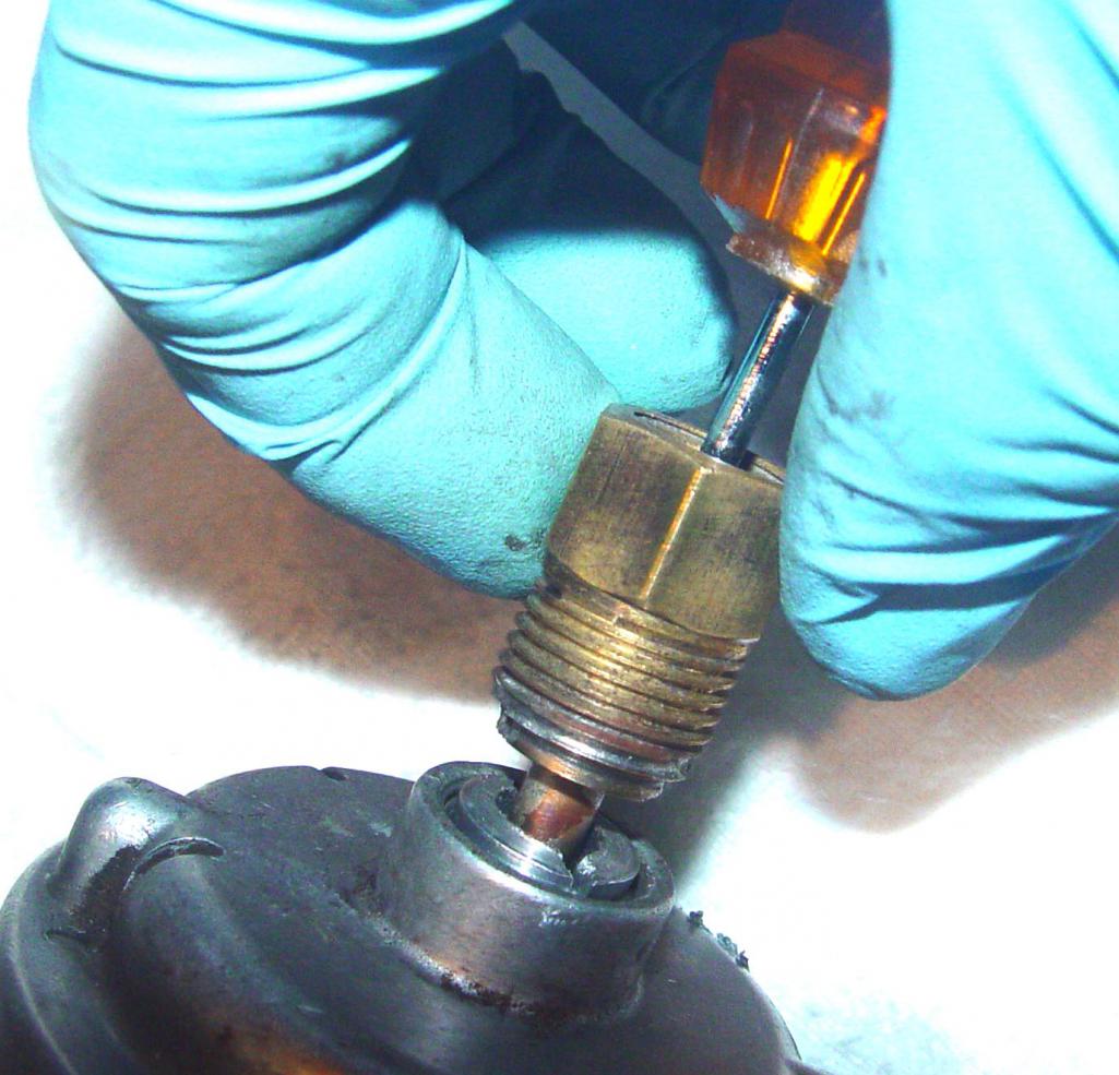 |
   |

 
|
| Java2570 |
Sep 9 2013, 09:49 AM
Post
#2
|
|
Senior Member Group: Members Posts: 649 Joined: 7-May 11 From: Fishers, IN Member No.: 13,035 Region Association: Upper MidWest |
Please do post about the Type 3/4 MPS...I've got a used one of those as well that I've been wondering about. I do think Chris Foley had tried one of those in his car and wasn't able to tune it right....I'm not positive though. I've seen SLITS mention them before so it would be a good project to try. Jon
|
|
|
|
| worn |
Sep 9 2013, 10:22 AM
Post
#3
|
|
can't remember Group: Members Posts: 3,156 Joined: 3-June 11 From: Madison, WI Member No.: 13,152 Region Association: Upper MidWest |
QUOTE(Java2570 @ Sep 9 2013, 07:49 AM)  Please do post about the Type 3/4 MPS...I've got a used one of those as well that I've been wondering about. I do think Chris Foley had tried one of those in his car and wasn't able to tune it right....I'm not positive though. I've seen SLITS mention them before so it would be a good project to try. Jon Here is where I am with that one... 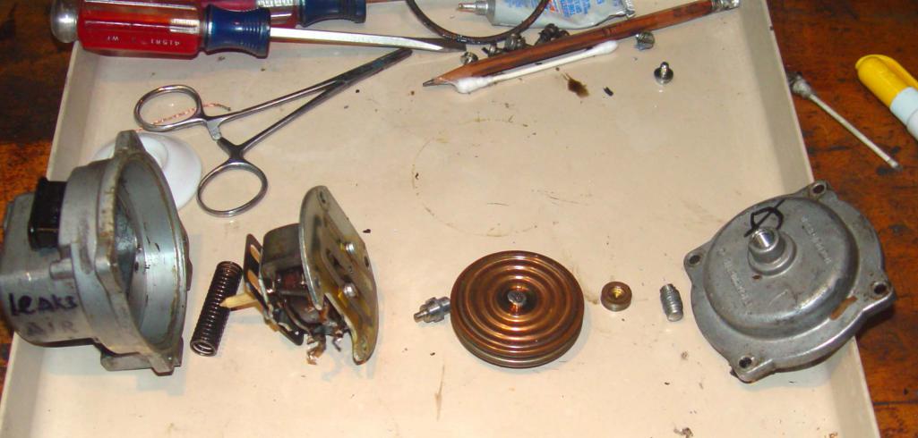 I found the leak, so that is OK. Need to solder in better wires though. Should be up and running soon, but whether it works is another question.. Notice only the aneroid cells - no diaphragm. |
|
|
|
| JeffBowlsby |
Sep 9 2013, 12:41 PM
Post
#4
|
|
914 Wiring Harnesses Group: Members Posts: 8,509 Joined: 7-January 03 From: San Ramon CA Member No.: 104 Region Association: None |
Creative! But why not just get the MPS tools from Tangerine? They are excellent and affordable.
|
 |
|
| worn |
Sep 9 2013, 12:55 PM
Post
#5
|
|
can't remember Group: Members Posts: 3,156 Joined: 3-June 11 From: Madison, WI Member No.: 13,152 Region Association: Upper MidWest |
QUOTE(Jeff Bowlsby @ Sep 9 2013, 10:41 AM) Creative! But why not just get the MPS tools from Tangerine? They are excellent and affordable. Everything there is excellent and affordable. As a postdoc I made my own gravel as a DIY project. (IMG:style_emoticons/default/chair.gif) So I think that answers that question. The purpose of the photos was to show that having access through the full throttle stop screw is helpful. And I didn't 'ave ter wait fer the post to arrive, eh? Just made it from what I already had. Speaking of dangerous sites to visit, do you think a full-on rebuild of my engine harness would be a good thing? The boots don't generally cover anything. Would you accept a 1.7 core for a 2.0 build? With appropriate extra fees of course. |
|
|
|
| JeffBowlsby |
Sep 9 2013, 01:32 PM
Post
#6
|
|
914 Wiring Harnesses Group: Members Posts: 8,509 Joined: 7-January 03 From: San Ramon CA Member No.: 104 Region Association: None |
Thats cool...you did it beacsue you could...[applause]. Ah, but that big hole in the WOT stop will be hard to seal too. What was your thesis on?
I can't say about your 'engine harness', it all depends on its condition. I assume you mean the FI harness? The boots perform four important functions: they protect the bare wires from heat damage, the electrical connections from dirt/moisture contamination, provide stress relief for the wires, and they keep the connector plugs secured to their components. I'd give you half a core value for a 1.7L core towards a 2.0L harness, if it has a 4-pole TPS, otherwise full core value. (IMG:style_emoticons/default/smile.gif) |
|
|
|
| worn |
Sep 9 2013, 01:58 PM
Post
#7
|
|
can't remember Group: Members Posts: 3,156 Joined: 3-June 11 From: Madison, WI Member No.: 13,152 Region Association: Upper MidWest |
QUOTE(Jeff Bowlsby @ Sep 9 2013, 11:32 AM) Ah, but that big hole in the WOT stop will be hard to seal too. What was your thesis on? Yeah, I was worried about that hole. For a while. I am trying to follow the great Anders in understanding these. In the older versions it would matter big time, because there is no big diaphragm. In our versions that stop is on the atmosphere side of the beryllium copper diaphragm that I got (I had to buy 2) from Chris. There are a couple of vent slits on that side of the housing and I am on the good side of the diaphragm. So, all I had to worry about was the bearing shoulder of the aluminum screw/plug so it would still make a stop at WOT. The red plug is there for style and dirt and water. |
|
|
|
| JeffBowlsby |
Sep 9 2013, 02:09 PM
Post
#8
|
|
914 Wiring Harnesses Group: Members Posts: 8,509 Joined: 7-January 03 From: San Ramon CA Member No.: 104 Region Association: None |
QUOTE(worn @ Sep 9 2013, 12:58 PM) QUOTE(Jeff Bowlsby @ Sep 9 2013, 11:32 AM) Ah, but that big hole in the WOT stop will be hard to seal too. What was your thesis on? Yeah, I was worried about that hole. For a while. I am trying to follow the great Anders in understanding these. In the older versions it would matter big time, because there is no big diaphragm. In our versions that stop is on the atmosphere side of the beryllium copper diaphragm that I got (I had to buy 2) from Chris. There are a couple of vent slits on that side of the housing and I am on the good side of the diaphragm. So, all I had to worry about was the bearing shoulder of the aluminum screw/plug so it would still make a stop at WOT. The red plug is there for style and dirt and water. ...yep...but the big hole lets in dirt/water/oil that can affect the seal of the diaphragm to case and I have seen the diaphrams deteriorate because of water/crud entrapment. The vents let water out, if they are not caked with stuff like some engine compartments get. |
|
|
|
| worn |
Sep 9 2013, 09:32 PM
Post
#9
|
|
can't remember Group: Members Posts: 3,156 Joined: 3-June 11 From: Madison, WI Member No.: 13,152 Region Association: Upper MidWest |
QUOTE(worn @ Sep 9 2013, 08:22 AM) QUOTE(Java2570 @ Sep 9 2013, 07:49 AM) Please do post about the Type 3/4 MPS...I've got a used one of those as well that I've been wondering about. I do think Chris Foley had tried one of those in his car and wasn't able to tune it right....I'm not positive though. I've seen SLITS mention them before so it would be a good project to try. Jon Here is where I am with that one... I found the leak, so that is OK. Need to solder in better wires though. Should be up and running soon, but whether it works is another question.. Notice only the aneroid cells - no diaphragm. Soldering and cleaning finished. Then, reassembly and vacuum tests to produce inductance curves. |
|
|
|
| DBCooper |
Sep 10 2013, 08:54 AM
Post
#10
|
|
14's in the 13's with ATTITUDE Group: Members Posts: 3,079 Joined: 25-August 04 From: Dazed and Confused Member No.: 2,618 Region Association: Northern California |
You graphed the curves? Then wouldn't it be a relatively easy thing to use a MAP or some other vacuum sensor to recreate the MPS functions in an electronic module? Replace the MPS altogether?
|
|
|
|
| worn |
Sep 10 2013, 12:25 PM
Post
#11
|
|
can't remember Group: Members Posts: 3,156 Joined: 3-June 11 From: Madison, WI Member No.: 13,152 Region Association: Upper MidWest |
QUOTE(DBCooper @ Sep 10 2013, 06:54 AM) You graphed the curves? Then wouldn't it be a relatively easy thing to use a MAP or some other vacuum sensor to recreate the MPS functions in an electronic module? Replace the MPS altogether? You would need to convert the MAP signal to inductance because that is what the brain senses (I am assuming the brain is pushing some sort of oscillations through the MPS). I have only limited electronics. If you can make a digitally controlled variable inductor, it ought to be possible. There are people out there with electronics chops who would have considered this I am sure. |
|
|
|
| DBCooper |
Sep 10 2013, 09:03 PM
Post
#12
|
|
14's in the 13's with ATTITUDE Group: Members Posts: 3,079 Joined: 25-August 04 From: Dazed and Confused Member No.: 2,618 Region Association: Northern California |
I don't have an MPS so this isn't a concern for me, but do you know how many MPS threads there have been over the years? What will happen when you can't find functional units any more, how to rebuild them, what alternatives might work, and so on. Seems it would be worth someone's time to put together a little electronic unit that just produced the needed signal without too much muss or fuss. And not just 914's, also the VW T3's/T4's, Volvos, etc. Just an observation. From ignorance, probably.
|
|
|
|
|
1 User(s) are reading this topic (1 Guests and 0 Anonymous Users)
0 Members:

|
Lo-Fi Version | Time is now: 17th May 2024 - 05:54 PM |
Invision Power Board
v9.1.4 © 2024 IPS, Inc.