|
|
|
Porsche, and the Porsche crest are registered trademarks of Dr. Ing. h.c. F. Porsche AG.
This site is not affiliated with Porsche in any way. Its only purpose is to provide an online forum for car enthusiasts. All other trademarks are property of their respective owners. |
|
|

  |

| jimkelly |
 Nov 7 2013, 08:41 AM Nov 7 2013, 08:41 AM
Post
#21
|
|
Delaware USA  Group: Members Posts: 4,969 Joined: 5-August 04 From: Delaware, USA Member No.: 2,460 Region Association: MidAtlantic Region |
I believe pin 30 is always connected to either 87 or 87a.
in my diagram, pin 30 is high current 12V. the fog lights get grounded. 85 (ground) and 86 (low current 12v) make the circuit for the low current switch. when the low current switch is activated, the high current circuit is engaged between 30 and 87. I believe i got that right? I edited this diagram to make up mine, as it seemed the most straight forward. interesting that fig B would require the use of all 5 pins on the relay. B is actually far slicker : ) Attached thumbnail(s) 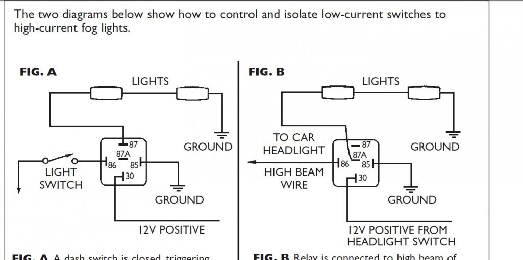
|
   |

 
|
| Spoke |
Nov 7 2013, 09:25 AM
Post
#22
|
|
Jerry Group: Members Posts: 7,370 Joined: 29-October 04 From: Allentown, PA Member No.: 3,031 Region Association: None |
QUOTE(jimkelly @ Nov 7 2013, 10:41 AM)  I believe pin 30 is always connected to either 87 or 87a. in my diagram, pin 30 is high current 12V. the fog lights get grounded. 85 (ground) and 86 (low current 12v) make the circuit for the low current switch. when the low current switch is activated, the high current circuit is engaged between 30 and 87. I believe i got that right? I edited this diagram to make up mine, as it seemed the most straight forward. interesting that fig B would require the use of all 5 pins on the relay. B is actually far slicker : ) You are correct. Pin 30 switches between 87 and 87a. When 85-86 = 0V; 30 = 87a; 87 open When 85-86 = 12V; 30 = 87; 87a open For Fig B, when the high beams are turned on, the relay coil is powered (85-86 = 12V), 30 = 87 and the fogs are off. With high beams off, 85-85 = 0V and 30 = 87a and power to fogs comes from 12V positive from headlight switch. A question with Fig B is that the switching on/off of the fogs comes from the 12V positive from headlight switch. What is the circuit for 12V positive from headlight switch? Is this another relay? It must be to switch the high current of the fogs. |
 |
|
| Dave_Darling |
Nov 7 2013, 09:43 AM
Post
#23
|
|
914 Idiot Group: Members Posts: 15,335 Joined: 9-January 03 From: Silicon Valley / Kailua-Kona Member No.: 121 Region Association: Northern California |
QUOTE(pcar916 @ Nov 7 2013, 01:19 AM) 30 is always a permanent ground. No, 30 should be the "hot" line! The relay will connect 30 to either 87a (when there is no voltage difference between 85 and 86) or to 87 (when there is a voltage difference between 85 and 86). Most of the relays have either constant power or switched power connected to 30. I can't think of one that has ground connected there. --DD |
|
|
|
| Mike Bellis |
Nov 7 2013, 09:56 AM
Post
#24
|
|
Resident Electrician Group: Members Posts: 8,348 Joined: 22-June 09 From: Midlothian TX Member No.: 10,496 Region Association: None |
Relay nomenclature:
30: Common 87: Nomally Open 87a: Normally Closed 85 & 86: coil power Circuits are ALWAYS drawn de-energized. |
|
|
|
|
1 User(s) are reading this topic (1 Guests and 0 Anonymous Users)
0 Members:

|
Lo-Fi Version | Time is now: 2nd April 2026 - 08:08 AM |
Invision Power Board
v9.1.4 © 2026 IPS, Inc.