|
|
|
Porsche, and the Porsche crest are registered trademarks of Dr. Ing. h.c. F. Porsche AG.
This site is not affiliated with Porsche in any way. Its only purpose is to provide an online forum for car enthusiasts. All other trademarks are property of their respective owners. |
|
|


| jd74914 |
 Dec 24 2013, 11:09 PM Dec 24 2013, 11:09 PM
Post
#1
|
|
Its alive  Group: Members Posts: 4,776 Joined: 16-February 04 From: CT Member No.: 1,659 Region Association: North East States |
Hello all.
I figured I’d throw up a progress thread for my car’s second rebuild. For those who don’t know me my name is James and I’ve been a 914 addict since age 13 (now 26) and used to hang around here a bunch more. It seems like a good start to this thread would be some background information. Its first build took place when I was in high school (age 13) and ended as a freshman in college. When I originally purchased the car it didn’t run and had some pretty serious external rust problems. I rebuilt the motor, fixed tons of electrical issues, replaced all of the rotten metal with new (all hand-formed since I didn’t have the money to pay for reproduction pieces), and repainted. Everything was done in my garage with the exception of turning/balancing the flywheel and I learned how to MIG weld and paint from my dad, some books, and through a lot of practice. After reassembly, it was my daily driver for 3.5 years during my undergrad degree. I pretty much drove it hard and put it away wet for the entirety of these years and it never saw a garage. Something about getting a mechanical engineering degree, dating a few girls, working throughout the year as a design engineering intern, and finding FSAE cars really limited the amount of time I spend on my own car. By the end of my undergrad degree there were some pretty rough spots, mostly in terms of the suspension/brakes and a pesky ignition switch (replaced 3 or 4 times and it kept failing), which pushed me to taking it off the road and fixing everything correctly. I thought it might take about a year-that was 3.5 years ago! (IMG:style_emoticons/default/wacko.gif) Just like after the first rebuild, life got in the way and the car sat as I went through a master’s degree, worked full time, continued to play with FSAE cars, and starting working on friend’s real racecars. Now I’ve finally finished my MS (and know way too much about fluid dynamics and heat transfer (IMG:style_emoticons/default/laugh.gif) ), am applying to schools for a Ph.D., still haven’t stopped [advising] FSAE design, and really want to drive her! The play was to start and finish rebuilding the suspension last summer (I saw Chris Foley-Racer Chris in the grocery store one day and told him this), but I got carried away and a bit behind. This thread is to chronicle the build back to the road. We’ll start with a few pictures from when it was originally completed in 2006/7 (well, it's missing the plates and still has the original windshield but...). 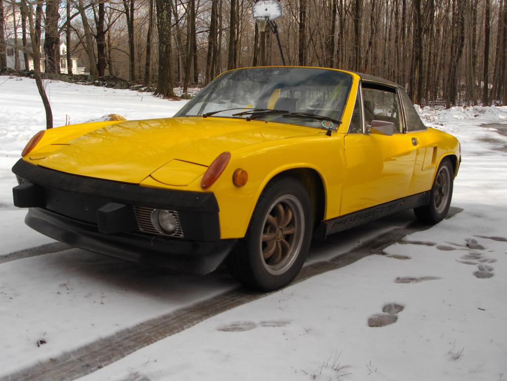 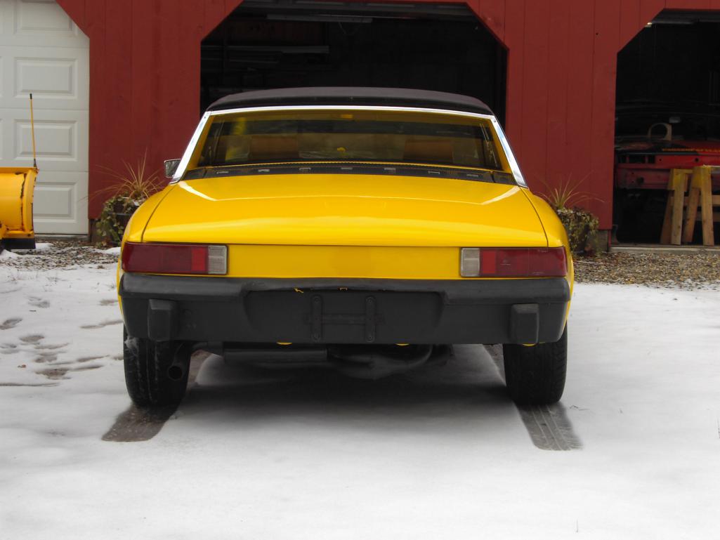 |
   |

 
|
  |
Replies(1 - 19)
| jd74914 |
Dec 24 2013, 11:41 PM
Post
#2
|
|
Its alive Group: Members Posts: 4,776 Joined: 16-February 04 From: CT Member No.: 1,659 Region Association: North East States |
***** Hijack Start *****
Since it’s been my main non-academic/vocational distraction for the last 7 years, a few OT FSAE pictures are probably warranted. For those who don’t know, FSAE is a college competition in which teams design and build a formula-style racecar for international competition. The cars are new every year, and the teams cycle members about every 3-4 years since they are academically-linked. I personally think it is the best learning experience for future engineers. And now for the sale’s plug: If anyone is interested in donating funds, components, or machining/RPing time, the guys would love to talk to you. 2013 UCONN FSAE Quick Spec. Notes Suspension 10" wheels, 18.5x7.5" tires Cast magnesium uprights 75 and 85 mm deep groove ball bearings Custom "hindle" - Integrated hub, spindle, wheel center(6061-T6) with 4340 RC50 tripod inserts Symmetric hindle design (same for all 4 corners) LSA suspension, push-rod actuated dampers, front ARB 100% Ackermann 30 deg max steering angle Kaz Tech/Cane Creek double-adjustable dampers Brakes Wilwood PS-1 Titon rear-pivot masters Remote-mount bias adjust Drivetrain Semi-custom salisbury differential (built using BMW E30 LSD clutches and ramps) Cast magnesium case, aluminum end caps 15.9# overall weight (including mounting pillow blocks, bearings, sprocket, stub axles, etc.) Custom 4340 tripod stub axles 3 speed transmission, max speed 77.9 mph @ 12 krpm (which has problems eating gears...now drive 2nd and driven 2nd and 6th are cryo'd and shot-peened) Chassis 4130, TIG welded, normalized 1800 ft-lb/degree twist 65# base frame weight, 70# fully loaded (not incl. stressed panels) CFRP stressed floor, firewall, rear bulkhead 435# assembled weight goal (haven't weighed yet) Engine/Controls 2001-2003 GSX-R600 motor 13:1 compression Est. 85 hp @ 9.5 krpm, 45 ft-lb @ 8 krpm Eq. length 4-2-1 headers tuned for 2nd resonant freq. @ 7.5 krpm, 18 ga mild steel, ceramic coated Ti Akropovic muffler Intake tuned for 2nd resonant freq. @ 8.5 krpm, 40% glass-filled nylon SLS 28mm SLS throttle body Performance Electronics PE-3 ECU Texense shift cut (programmed ignition cut in ECU for clutchless shifting) Manual shifter/hand clutch 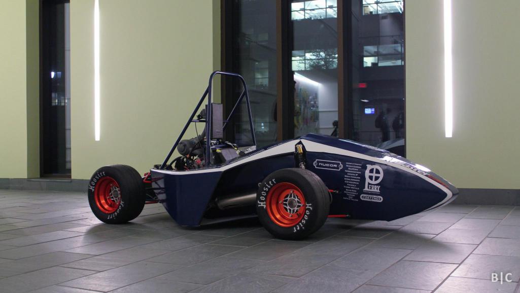 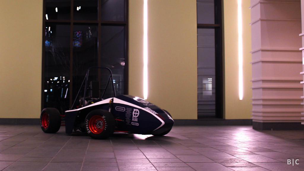 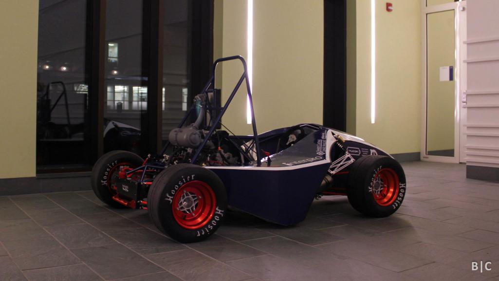 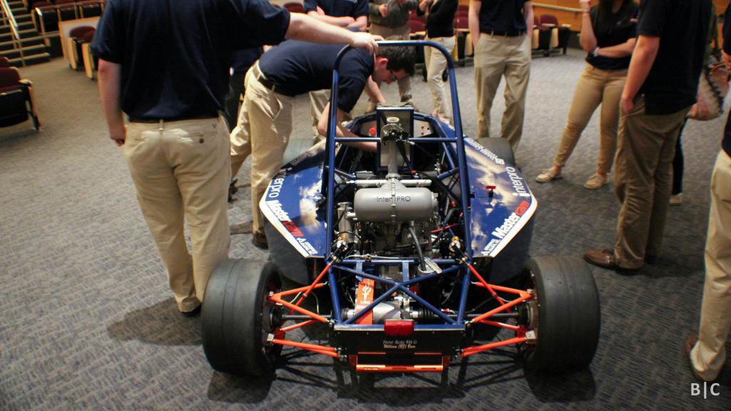 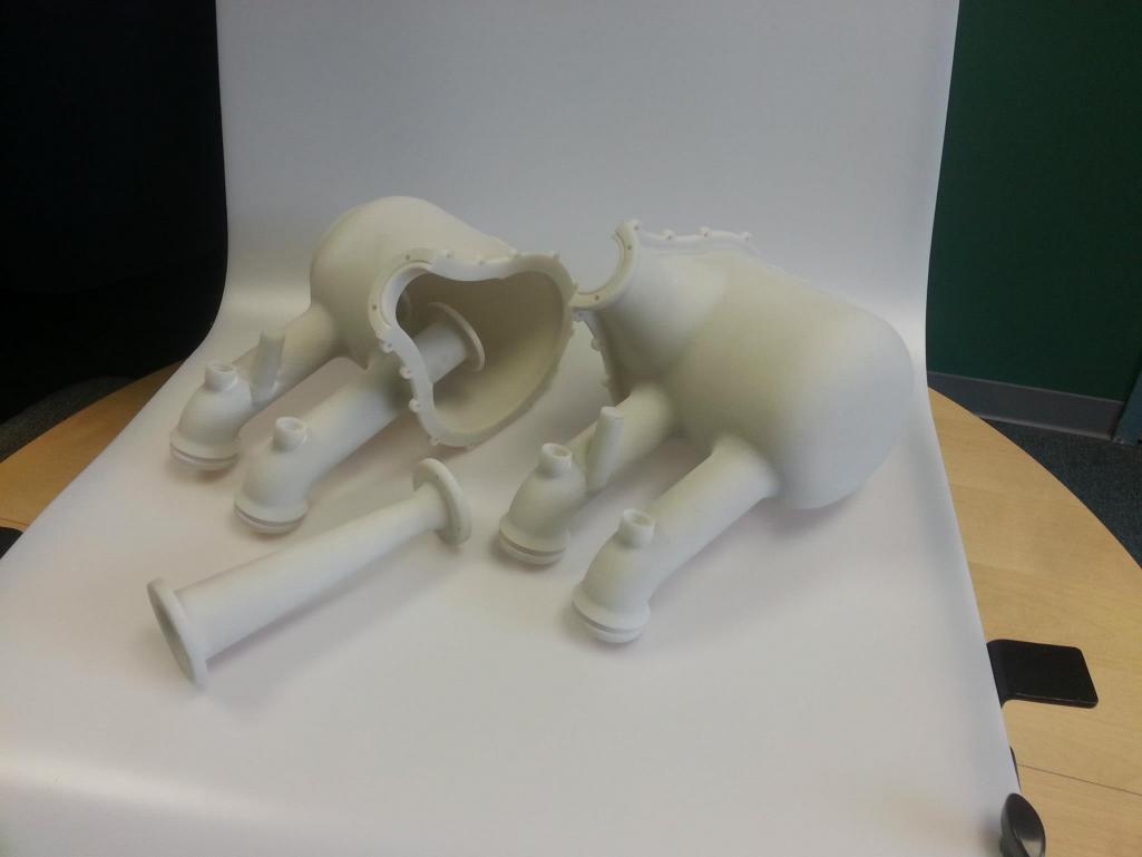 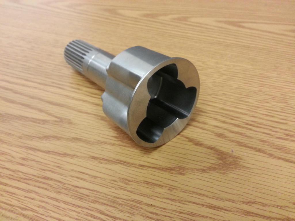 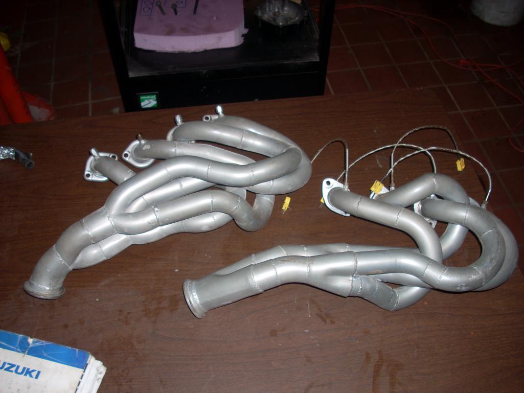 |
|
|
|
| jd74914 |
Dec 24 2013, 11:46 PM
Post
#3
|
|
Its alive Group: Members Posts: 4,776 Joined: 16-February 04 From: CT Member No.: 1,659 Region Association: North East States |
And a few shop pics just because...There is a nice Stuska dyno, manual lathe, and pretty OK design room with computers as well (always looking for more CFD/FEA machines (IMG:style_emoticons/default/laugh.gif) ).
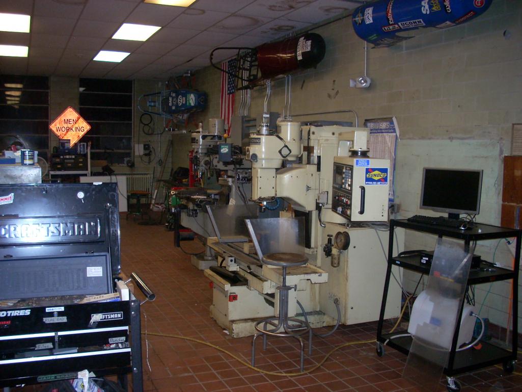 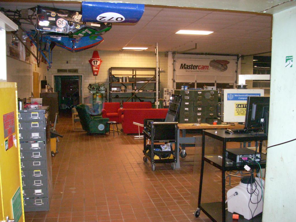 ***** Hijack over - Back to normal programming ***** |
|
|
|
| EdwardBlume |
Dec 25 2013, 07:31 AM
Post
#4
|
|
914 Wizard Group: Members Posts: 12,338 Joined: 2-January 03 From: SLO Member No.: 81 Region Association: Central California |
Good luck with your build(s)....
|
|
|
|
| r_towle |
Dec 25 2013, 10:40 PM
Post
#5
|
|
Custom Member Group: Members Posts: 24,560 Joined: 9-January 03 From: Taxachusetts Member No.: 124 Region Association: North East States |
Good to see you back at it again, now stop getting distracted and get her going again.
You may want to research the option of a push button starter switch like some race cars use, along with the reliable power function of the ignition switch. Rich |
|
|
|
| jd74914 |
Dec 25 2013, 11:55 PM
Post
#6
|
|
Its alive Group: Members Posts: 4,776 Joined: 16-February 04 From: CT Member No.: 1,659 Region Association: North East States |
Thanks Rich and Rob...I'm definitely trying to get her going...albeit somewhat slowly as I'm pretty easily distracted. (IMG:style_emoticons/default/laugh.gif)
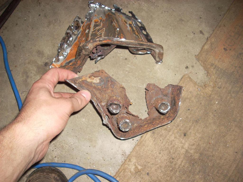
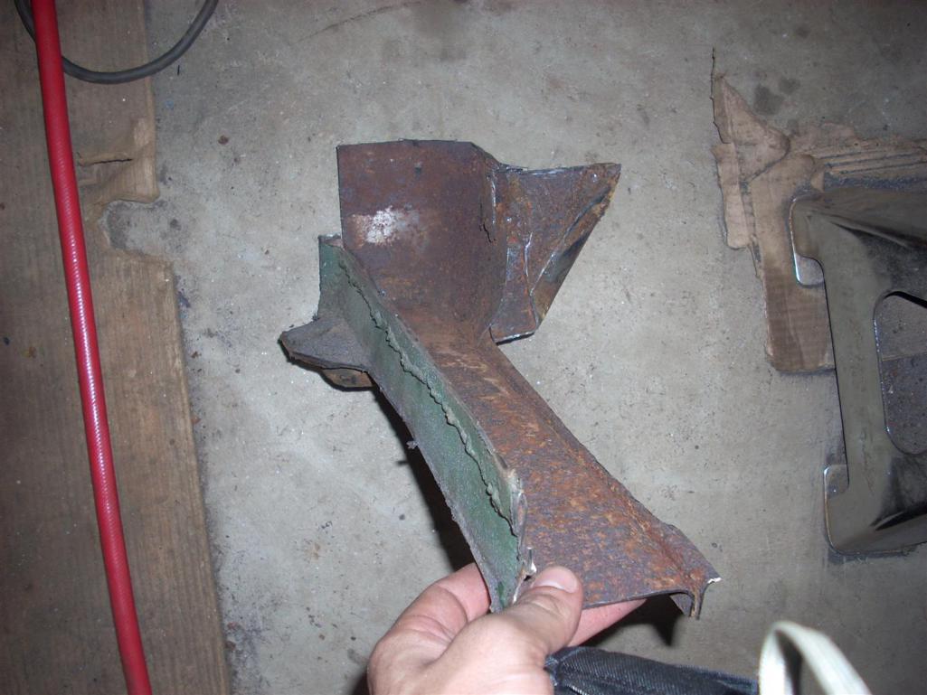
My initial plan (May 2013) was to replace the stock EFI with a MegaSquirt3. When I was actually driving the car, I had been having problems with intermittent failures and random broken wires. Figuring that these problems were mostly related to the 40 year old wires, the easiest solution seemed like remaking the FI harness. After thinking about it a little more, it seemed like a waste to remake an entire wire harness and still be handicapped by an antiquated controller. I’ve had experience building harnesses and tuning with a few aftermarket engine management systems [Performance Electronics PE1 and PE3, Adaptronic e420c, MicroSquirt] through FSAE and some other modified car builds so I picked the MS3 mostly for the cost and fact that I haven’t had the opportunity to play with any newer MS stuff. The first step in any harness build is measuring out the harness end locations, so I pulled the motor to measure wire lengths, add cam/crank position sensors, reseal the oil cooler, and repaint the tin. As I was doing this I noticed some rust on “jacking” donuts and rear right trailing arm mounts so out they came. While in there I started poking at the frame rails and noticed some rot so out they came as well. The first few pictures show some of the damage and then the quick suspension jig made to keep everything aligned after cutting. The door jams are also braced with angle welded from the upper seat belt bolt mounts to lower door jambs. 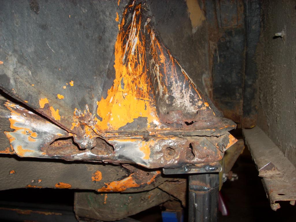 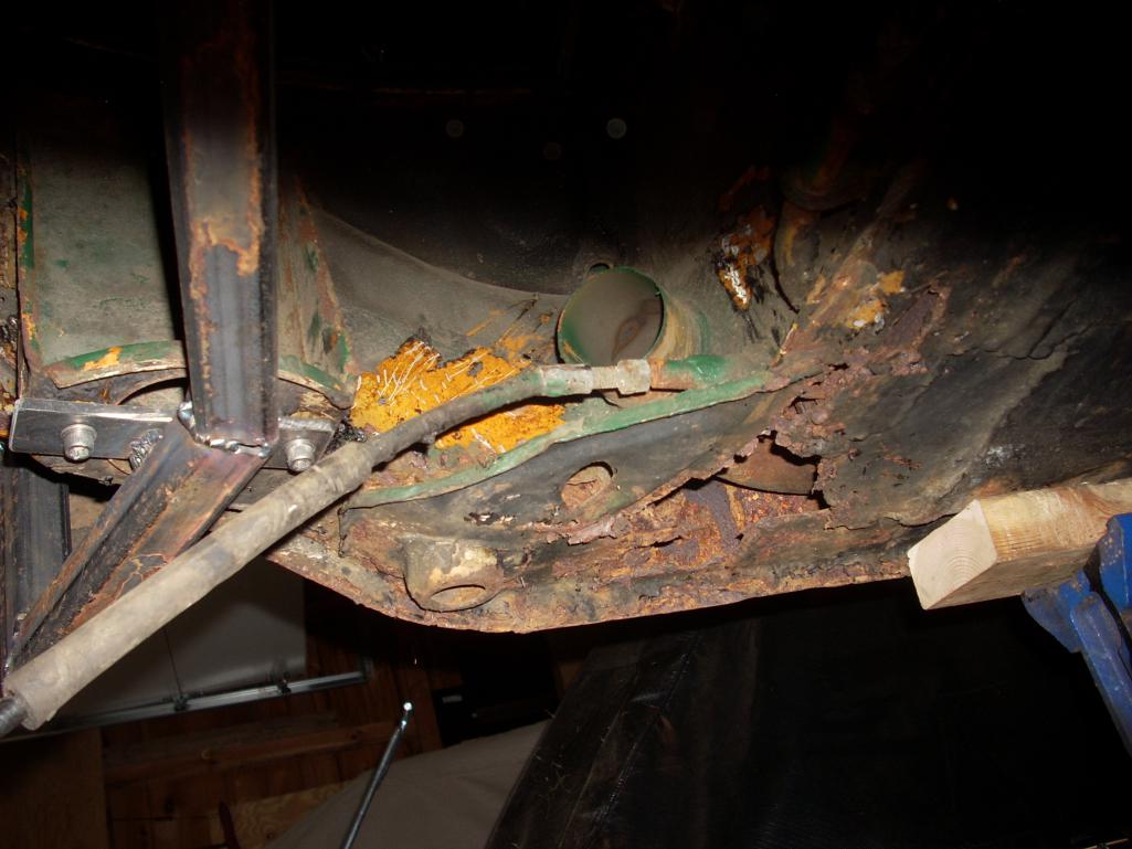 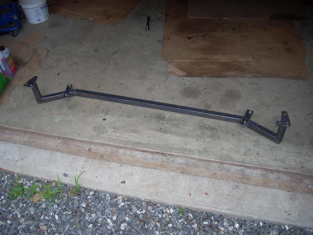 |
|
|
|
| jd74914 |
Dec 26 2013, 12:04 AM
Post
#7
|
|
Its alive Group: Members Posts: 4,776 Joined: 16-February 04 From: CT Member No.: 1,659 Region Association: North East States |
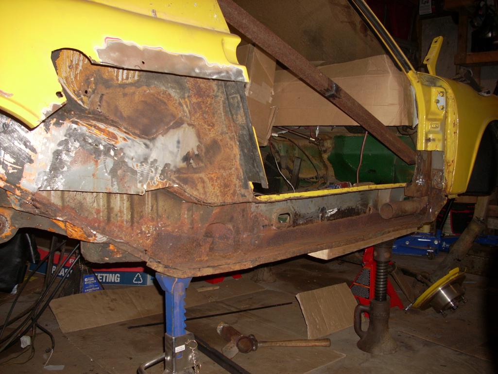
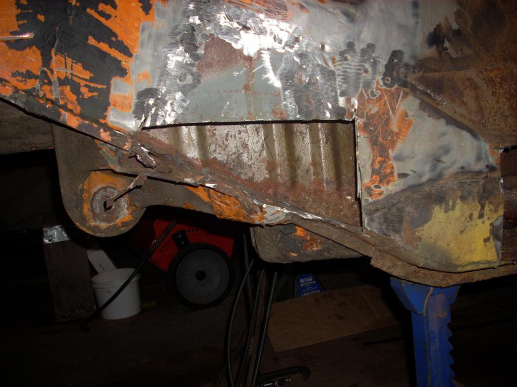
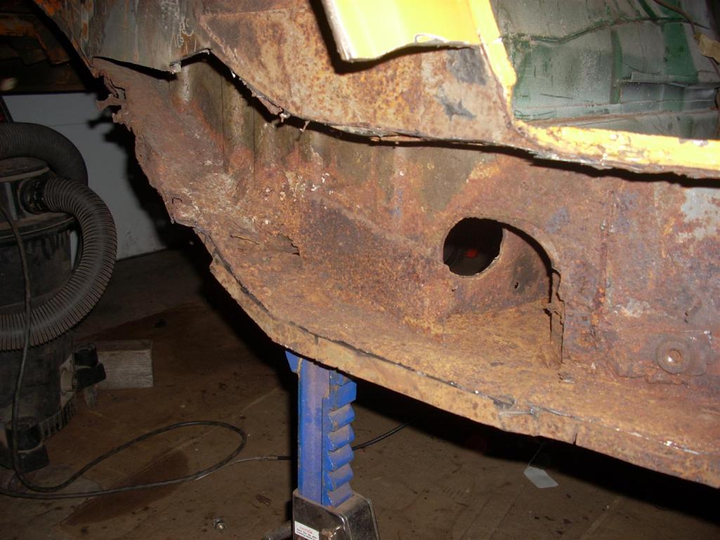
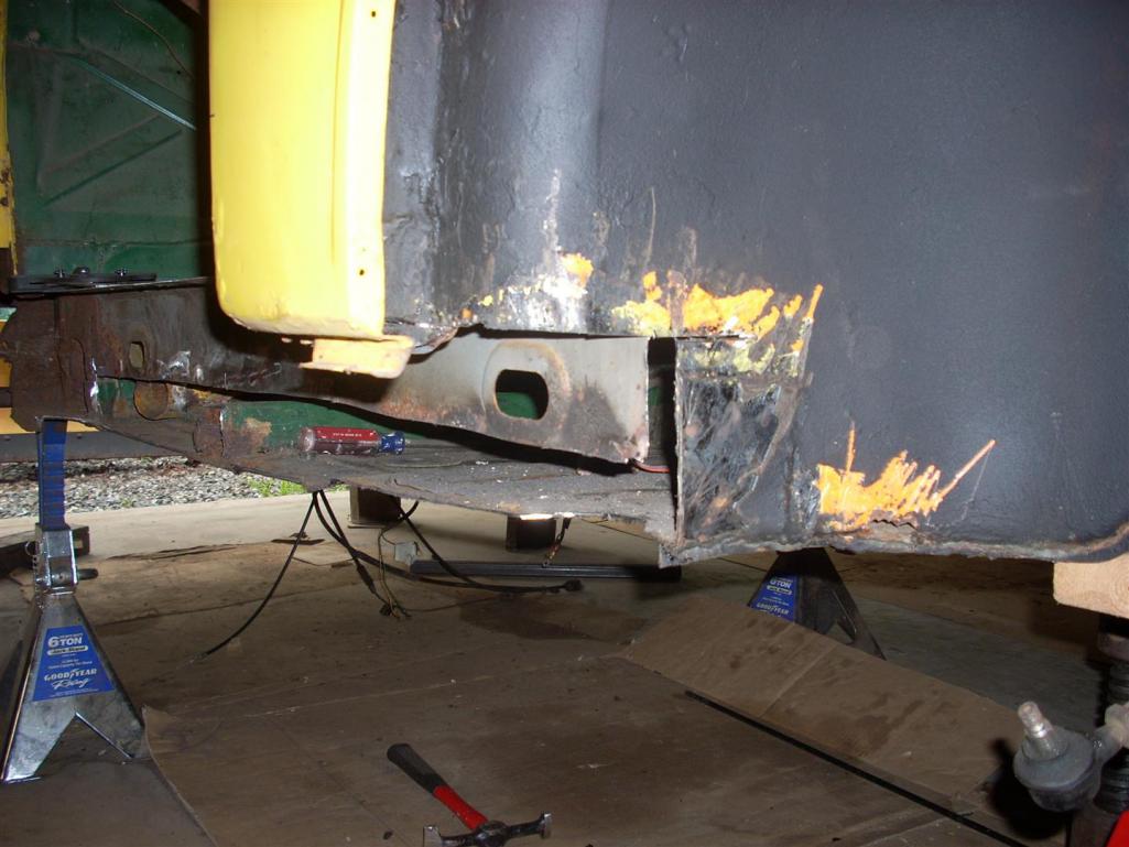
Off came the fender for easy cutting into the longs. That's only a little rust, right? (IMG:style_emoticons/default/laugh.gif)
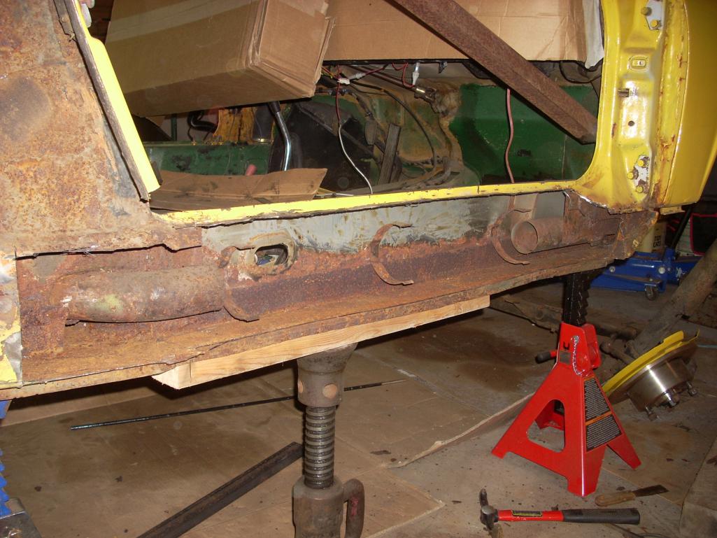
Note the old patch (80's perhaps) on the bottom left part of the image. 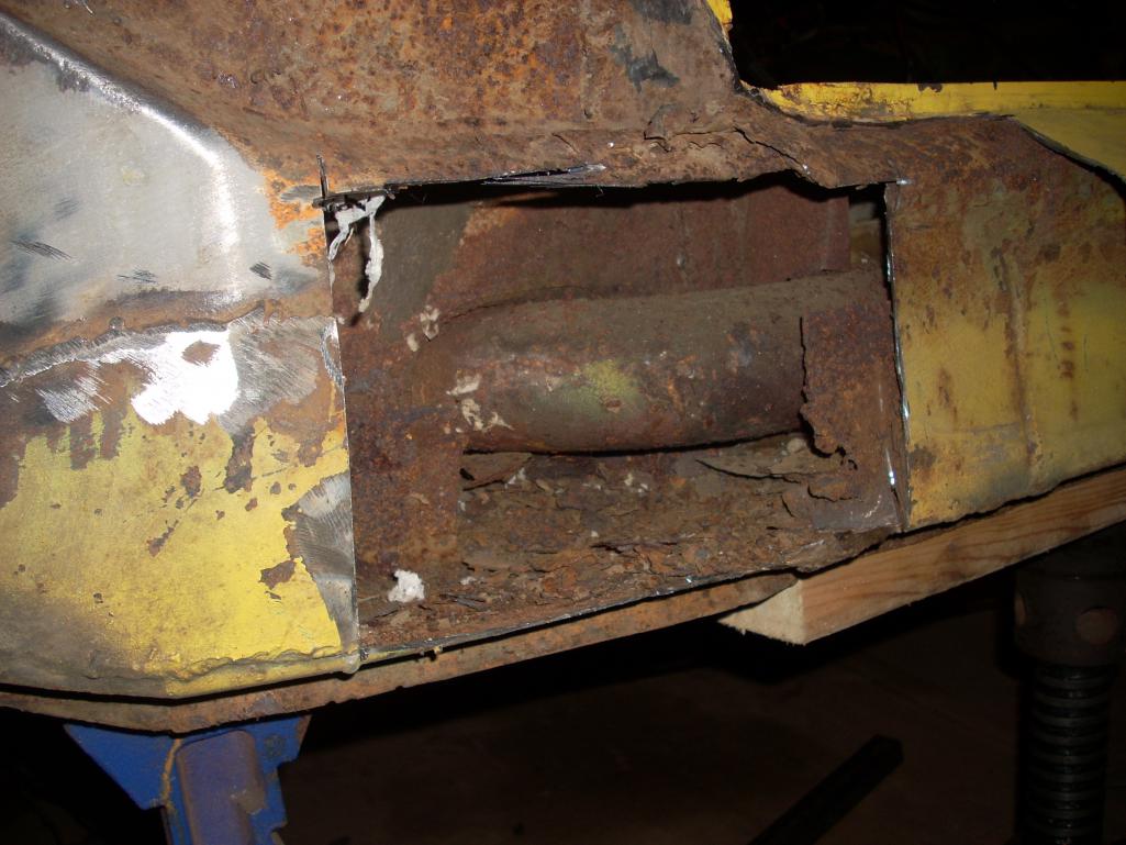 A view from the back (read: I hate jack posts). 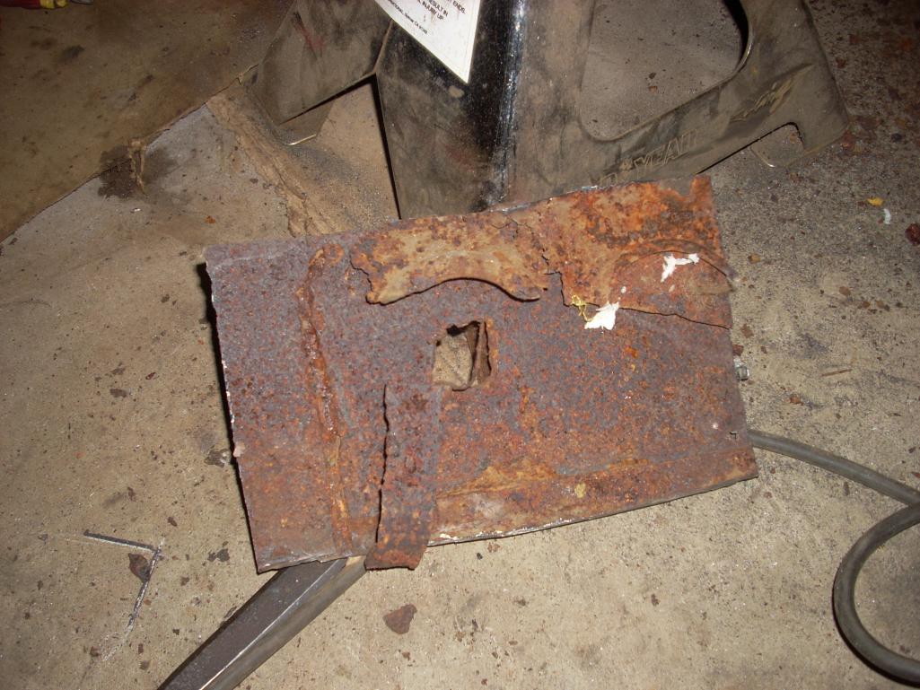 Don't you love thresholds covering old rusty thresholds? (IMG:style_emoticons/default/dry.gif) 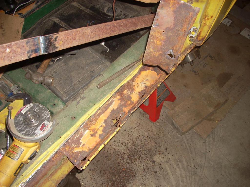 |
|
|
|
| jd74914 |
Dec 26 2013, 12:15 AM
Post
#8
|
|
Its alive Group: Members Posts: 4,776 Joined: 16-February 04 From: CT Member No.: 1,659 Region Association: North East States |
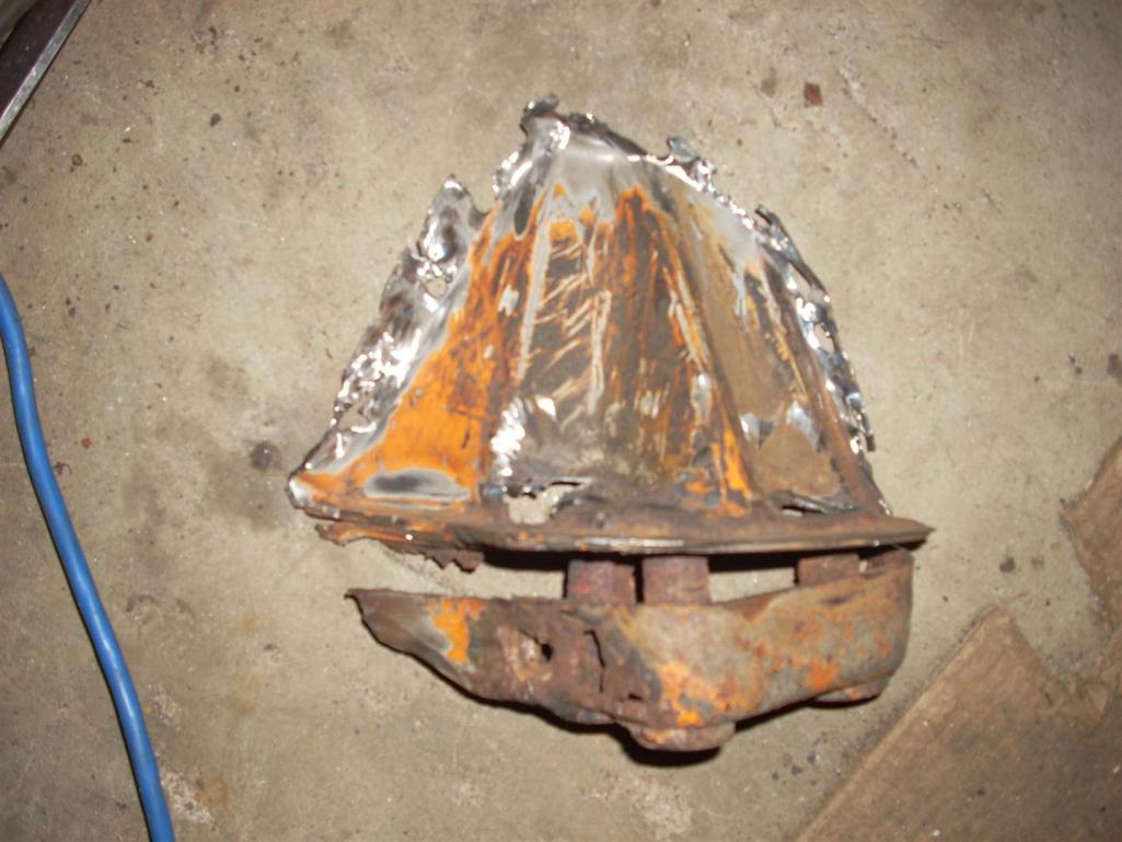
Once the cutting started, I had a really hard time stopping...
  |
|
|
|
| jd74914 |
Dec 26 2013, 12:38 AM
Post
#9
|
|
Its alive Group: Members Posts: 4,776 Joined: 16-February 04 From: CT Member No.: 1,659 Region Association: North East States |
A few more pictures of the suspension console and long. deconstruction.
    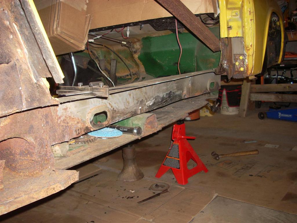   I'm on the quest to get everything up-to-date so more to come tomorrow. |
|
|
|
| Cairo94507 |
Dec 26 2013, 09:17 AM
Post
#10
|
|
Michael Group: Members Posts: 9,708 Joined: 1-November 08 From: Auburn, CA Member No.: 9,712 Region Association: Northern California |
Terrific story and glad to see you are working towards your Ph.D - single biggest factor in being able to continue playing with our cars. I love seeing these cars go under the knife to repair their rusting bones. Best wishes and have fun restoring your lifetime friend.
|
|
|
|
| jd74914 |
Dec 27 2013, 01:59 AM
Post
#11
|
|
Its alive Group: Members Posts: 4,776 Joined: 16-February 04 From: CT Member No.: 1,659 Region Association: North East States |
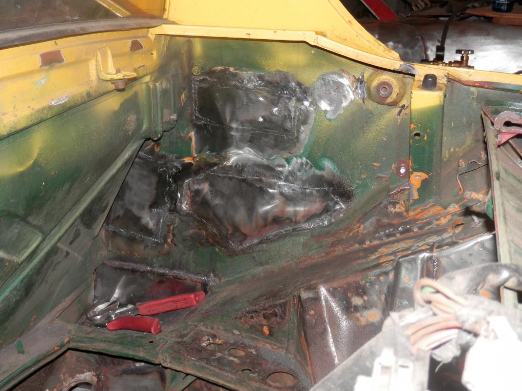
QUOTE(Cairo94507 @ Dec 26 2013, 10:17 AM)  Terrific story and glad to see you are working towards your Ph.D - single biggest factor in being able to continue playing with our cars. I love seeing these cars go under the knife to repair their rusting bones. Best wishes and have fun restoring your lifetime friend. Thanks! (IMG:style_emoticons/default/smile.gif) The last pictures ended with about 60% of the right long pulled off and a whole bunch more metal cut out. Since the car was dimensionally-unstable at this point, the immediate need was to fix most of the structure. The next pictures show the first portion of the inner long fix. You'll notice that I'm not remaking the metal in exactly the same fashion as it was removed, it's actually about 12mm taller than the original cross-section and will have extra stiffening plates installed on the top and bottom faces. This modification increases stiffness more than an Engman kit (I'm tired now, but I'll write in the moment of inertial calculations later) without adding much additional weight (it's stiffness-to-weight efficiency is actually much better than Engman's and slightly better than the factory). It also has the added benefit of being essentially free since I'm making all of the pieces from sheet anyways. The oddly placed channel is for this buildup. When I get to posting the math details I'll also post a sketch of the new metal so everyone who wants can see how I'm adding it. The inner fender well repair panel needed to have a slightly odd end finish to match the frame rail end, but I think it came out pretty nicely. The rest of the pictures show some additional metal replacement at the engine mounts and hot air inlet duct section. Chances are these heater ducts will not come back in as originally intended and will instead become wire chase-ways for the ECU. The duct cutout in the new metal at duct inlet is funny looking (weird non-oval shape) since it has yet cut to the exact opening. The hell hole bottom wasn't too bad, but while in there seemed like a prudent replacement. That's all for now...so enjoy some pictures. (IMG:style_emoticons/default/smile.gif) 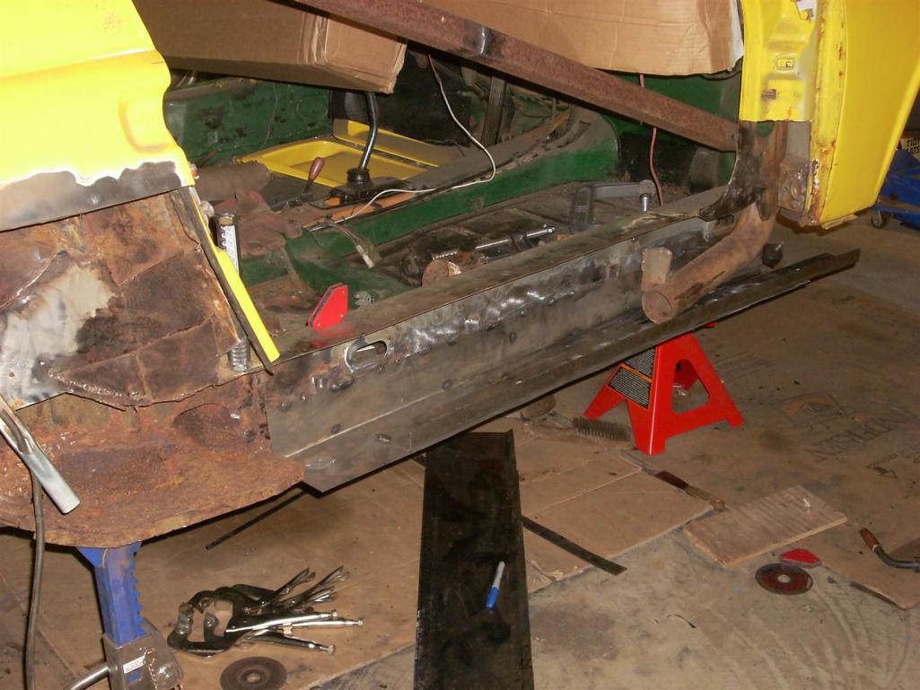 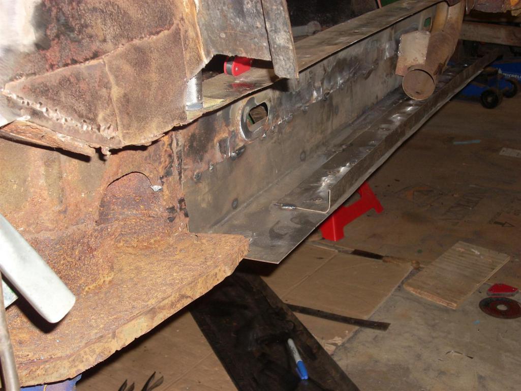 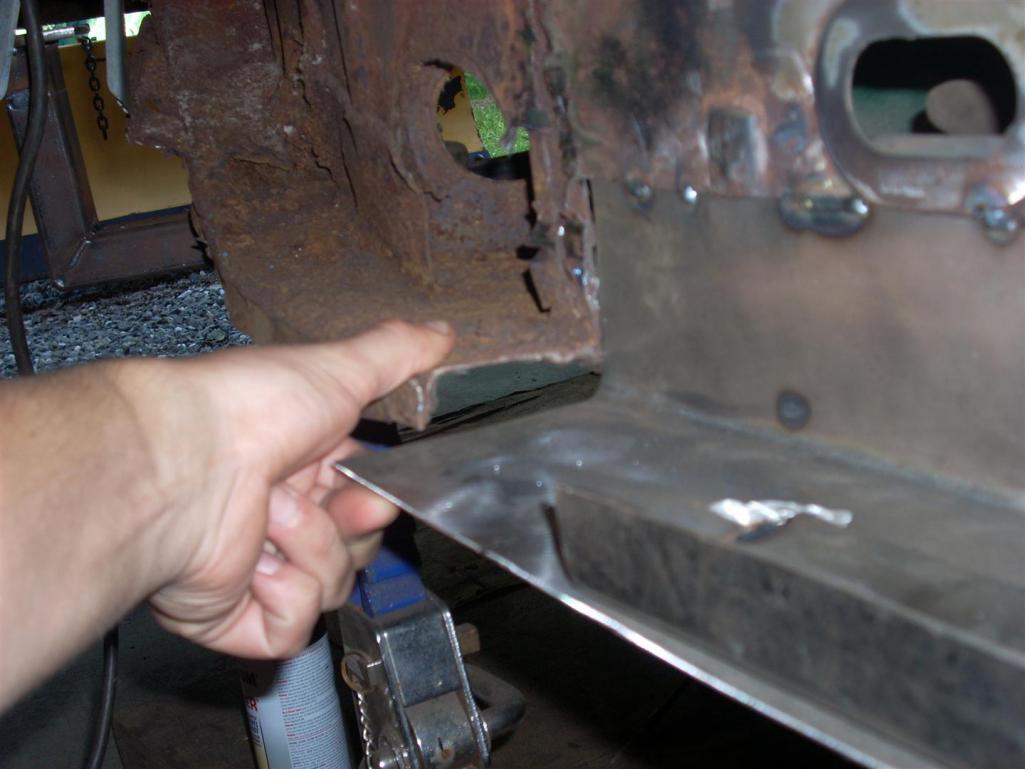 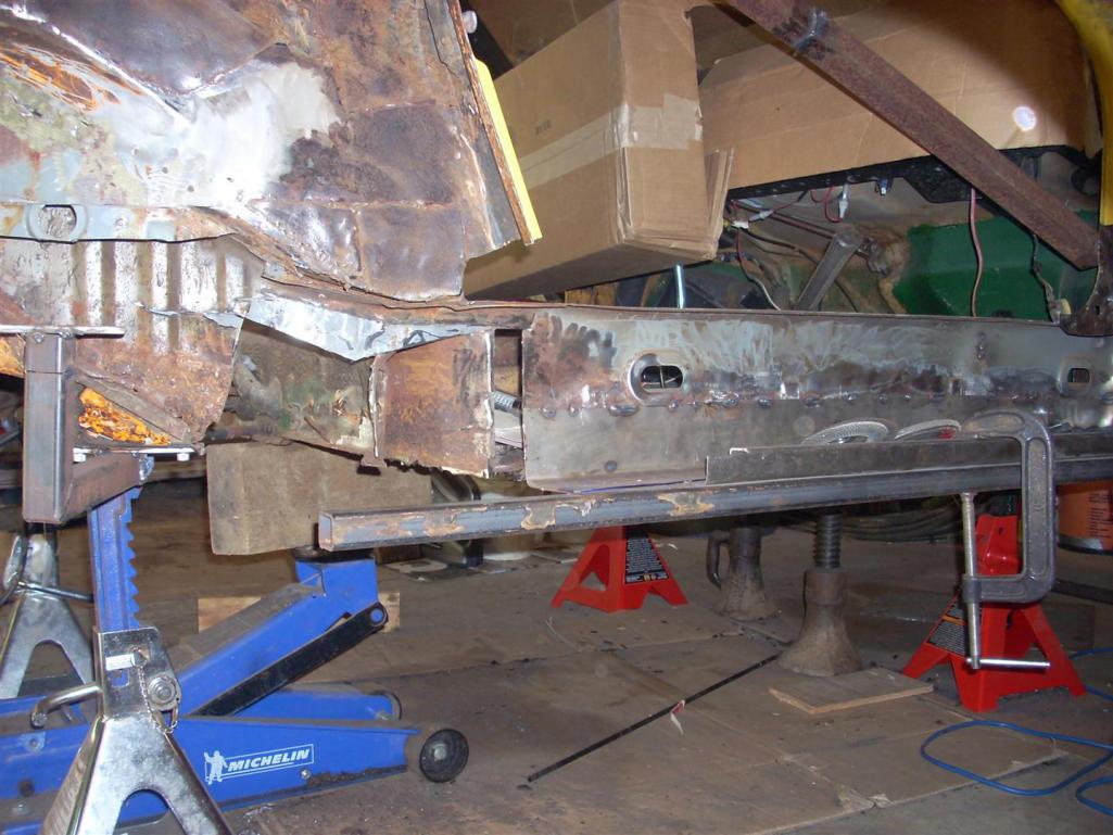 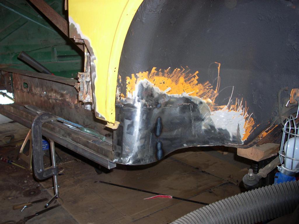 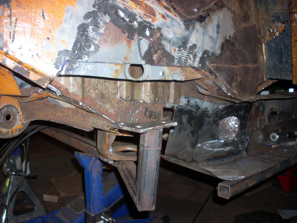 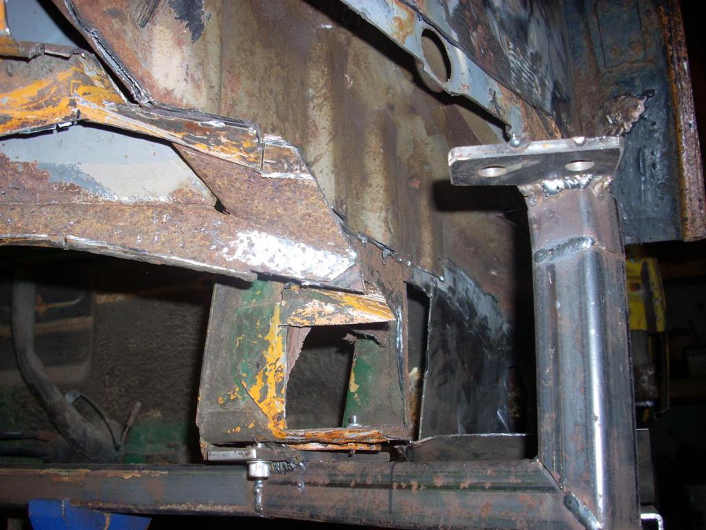 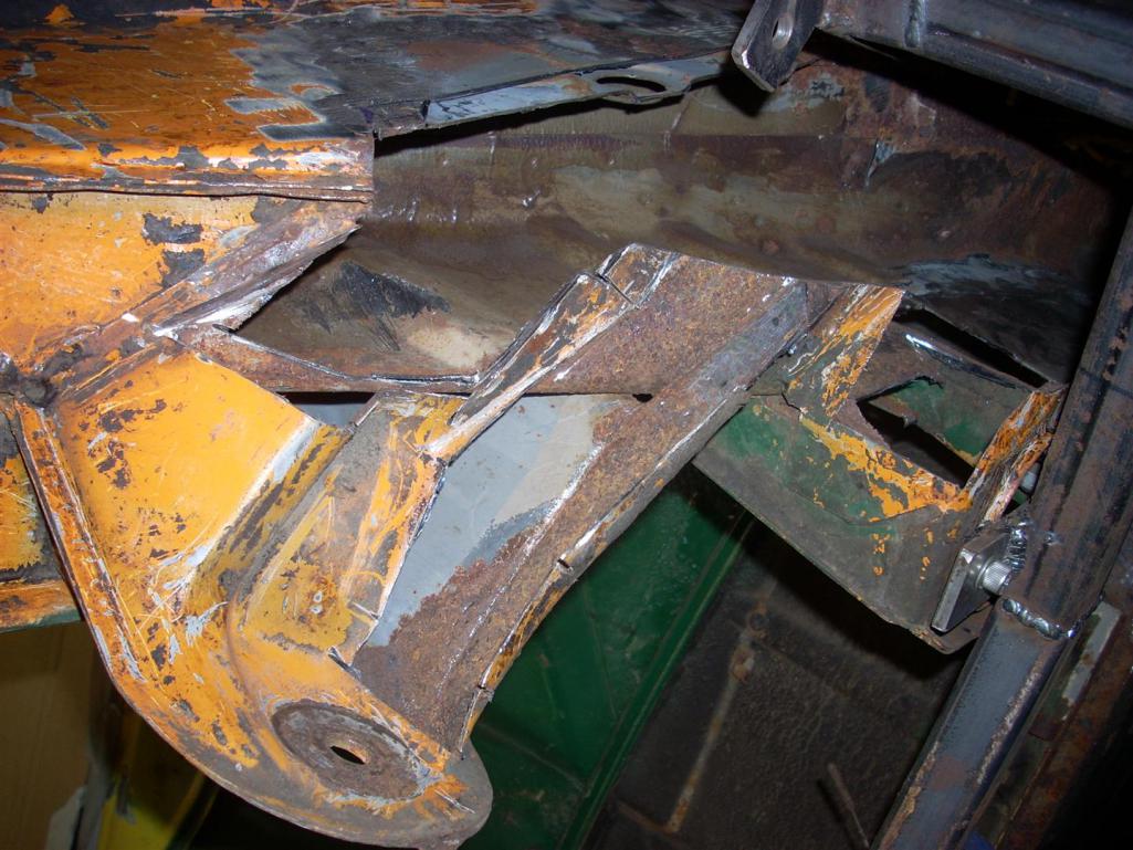 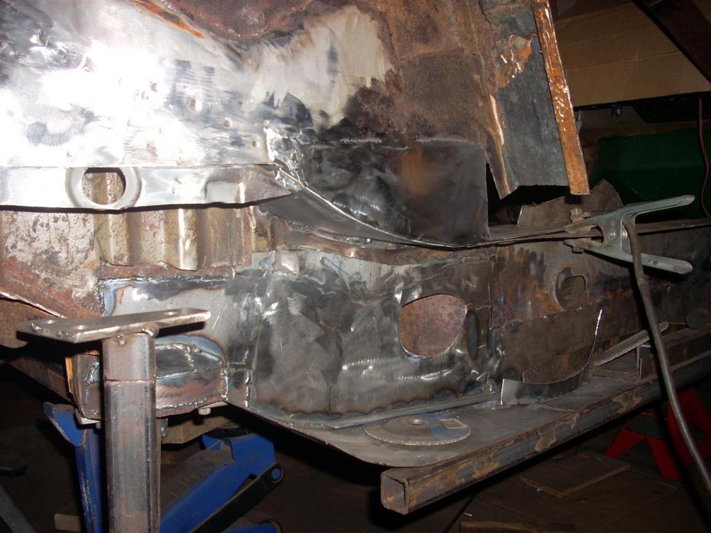 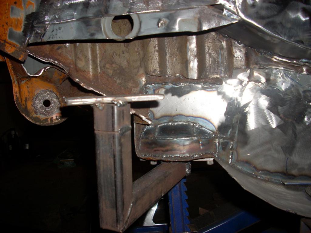 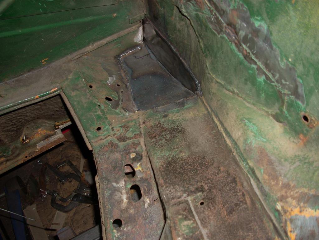 |
|
|
|
| ChrisFoley |
Dec 27 2013, 07:59 AM
Post
#12
|
|
I am Tangerine Racing Group: Members Posts: 7,909 Joined: 29-January 03 From: Bolton, CT Member No.: 209 Region Association: None |
Wow, a little bit of project creep there. Better now than later though.
Looks like a good time to install a raised suspension pickup kit while you're at it. (IMG:style_emoticons/default/smile.gif) We have a chassis here which needs much of the same repair work. Ed's busy bolting it down to our Slutty bench right now. |
|
|
|
| r_towle |
Dec 27 2013, 06:38 PM
Post
#13
|
|
Custom Member Group: Members Posts: 24,560 Joined: 9-January 03 From: Taxachusetts Member No.: 124 Region Association: North East States |
When the heck did you do that? Last week?
And Chris, I must have missed the slutty bench last time I was there, it's on my must see list how. |
|
|
|
| jd74914 |
Dec 27 2013, 11:52 PM
Post
#14
|
|
Its alive Group: Members Posts: 4,776 Joined: 16-February 04 From: CT Member No.: 1,659 Region Association: North East States |
QUOTE(Racer Chris @ Dec 27 2013, 08:59 AM) Wow, a little bit of project creep there. Better now than later though. Looks like a good time to install a raised suspension pickup kit while you're at it. (IMG:style_emoticons/default/smile.gif) Yes, just a little scope creep. I figured it'd be nice to build what I [think I] want the first time around. I just raised the front spindles and have been thinking about the rear. (IMG:style_emoticons/default/laugh.gif) QUOTE Ed's busy bolting it down to our Slutty bench right now. (IMG:style_emoticons/default/lol-2.gif) QUOTE(r_towle @ Dec 27 2013, 07:38 PM) When the heck did you do that? Last week? Hahaha A few weeks ago...I'm trying to get everything up to date now. -------------------------- As a change of pace I raised my front spindles 18mm (slightly under the fit limit of a 15 inch wheel). Since I started with tapered Boge struts, raising required a little sectioning rather than a simple weld cut, press, and new weld. I sectioned a length from the strut top, cut the strut bottom, and then TIG'd the spool in. Note that the sectioned piece needed to be tacked and then shaved length-wise to fit the strut bottom's smaller dimensions. Unfortunately, I didn't take pictures of the process, only the "final" product. Note that I'm going to put a RSR-style double shear tie rod mount onto the strut, machine a tapered bolt to fit the existing tie rod end, and a few spacers to play with the bumpsteer. 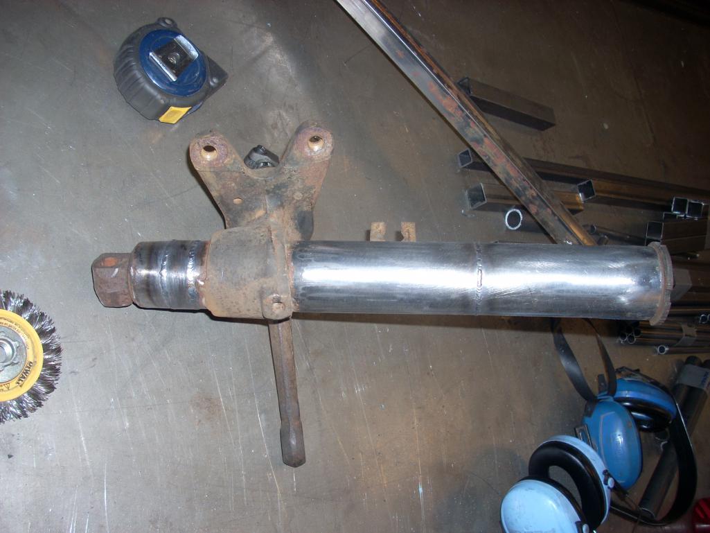 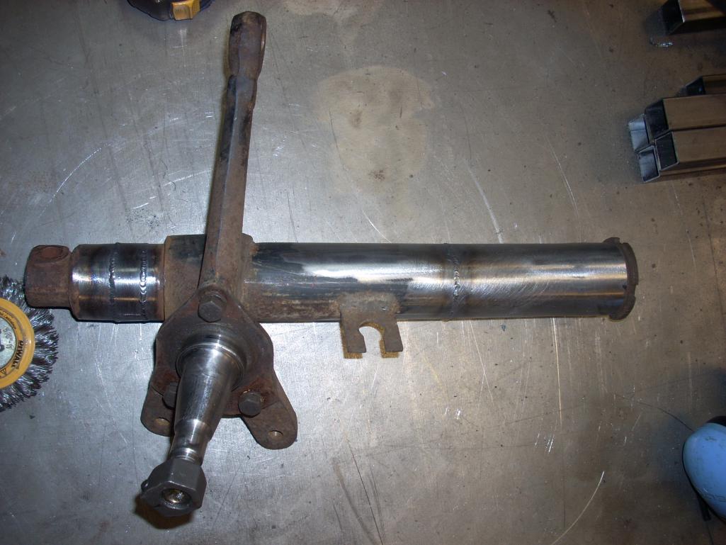 *The strut housings are straight despite ho they might look in pictures. (IMG:style_emoticons/default/smile.gif) |
|
|
|
| saigon71 |
Dec 28 2013, 08:45 AM
Post
#15
|
|
Senior Member Group: Members Posts: 1,997 Joined: 1-June 09 From: Dillsburg, PA Member No.: 10,428 Region Association: MidAtlantic Region |
Looking good...especially the jig to insure the suspension console is in the right spot.
In my experience, project creep just happens with these cars. (IMG:style_emoticons/default/beerchug.gif) |
|
|
|
| jd74914 |
Dec 29 2014, 03:09 PM
Post
#16
|
|
Its alive Group: Members Posts: 4,776 Joined: 16-February 04 From: CT Member No.: 1,659 Region Association: North East States |
A late thanks Bob! (IMG:style_emoticons/default/smile.gif)
I was going through my camera and found some pictures of the next steps of this project (only a year after the last post haha). In the past year I've jet-set all over the place for work, lost my job due to company bankruptcy, signed up for full time doctoral research in laser diagnostics, started an engineering consulting gig, had the opportunity to play with LeMans-grade engine control hardware (see Life Racing F88) and way too much more so my 914 progress has been super slooooooooooooooooooow. (IMG:style_emoticons/default/blink.gif) (IMG:style_emoticons/default/smile.gif) Hopefully life will let me get a little more done this year! (IMG:style_emoticons/default/laugh.gif) The first pictures show fixes to the general inner fender structure where the metal was either soft or had been poorly replaced the first time around. 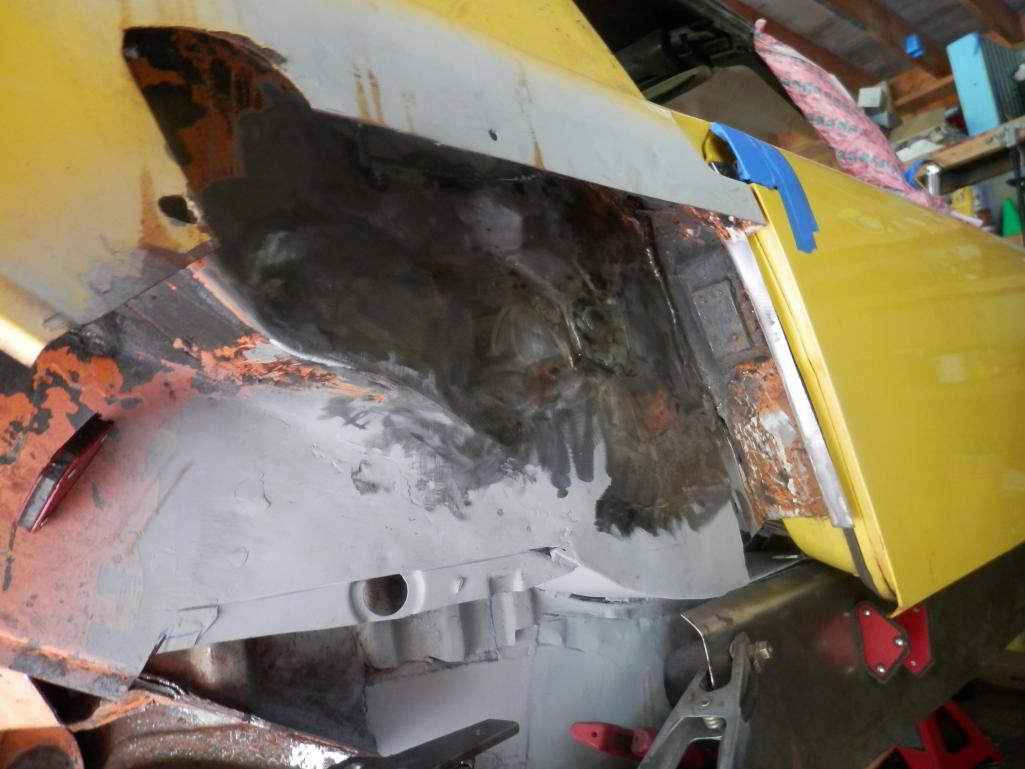 |
|
|
|
| jd74914 |
Dec 29 2014, 03:10 PM
Post
#17
|
|
Its alive Group: Members Posts: 4,776 Joined: 16-February 04 From: CT Member No.: 1,659 Region Association: North East States |
 |
|
|
|
| ChrisFoley |
Dec 29 2014, 03:15 PM
Post
#18
|
|
I am Tangerine Racing Group: Members Posts: 7,909 Joined: 29-January 03 From: Bolton, CT Member No.: 209 Region Association: None |
QUOTE(jd74914 @ Dec 29 2014, 04:09 PM) ... , lost my job due to company bankruptcy, ... How convenient for the new company to run out of money so quickly. Previous owner seemed to make it work for the long term. I wondered how you made out when that happened but figured you would land on your feet either way. |
|
|
|
| r_towle |
Dec 29 2014, 03:23 PM
Post
#19
|
|
Custom Member Group: Members Posts: 24,560 Joined: 9-January 03 From: Taxachusetts Member No.: 124 Region Association: North East States |
is the car originally green, orange, or yellow?
|
|
|
|
| jd74914 |
Dec 29 2014, 03:43 PM
Post
#20
|
|
Its alive Group: Members Posts: 4,776 Joined: 16-February 04 From: CT Member No.: 1,659 Region Association: North East States |
Over the course of last winter, I couldn't stop thinking about lowering the rear of the car. Unfortunately, I wasn't comfortable dropping the roll center super low just by cranking down on a set of threaded spring perches without making any kinematic changes. I actually drew up both the front and rear suspension in a kinematic software I have access to and looked into modifying the pivot points, etc. Through this modeling I decided to raise the rear trailing arm mounts (just as a note changing from trailing arm to multi-link suspension was considered, but in the end I decided to stay semi-trailing arm since an suspension genre switch is really easier in a full custom car).
Additionally the car needed new bushings. As this project was moving more into the realm of questionably street-able I decided to try something different and switch to spherical bearings in the rear pivots. I'm still a little worried about how they are going to work, but my rationale was that in the worst case I would just throw away my modified arms and cut the inner pivot out of the car for replacement with something a different. The cost to change is pretty low so I'm not too worried; the most disappointing part would be throwing away the machining necessary to make the new "pivot shafts." Just for size reference, the sphericals have a 3/4" bore. I went with this size because it most closely matched the size of the existing pivots. I don't remember the exact numbers, by the factor of safety for the spherical (radially-loaded) is something like 8 if the car experiences a 3g bump, 2g brake, and 2g lateral load all at the same time with the entire weight of the car on a rear wheel. (IMG:style_emoticons/default/laugh.gif) Anyways, the next pictures show a little suspension modeling (no real kinematics unless some really wants to see plots) and then the trailing arm inserts. They were machined as such because I did not want a stress concentration for the bolt at the trailing arm/spherical interface. As designed, the bolt shank goes through the spherical and into a flat in the trailing arm and the the threaded portion starts. The tube everything is combined in gets pressed into the trailing arms and the edges welded. I don't have pictures of the part but it all went pretty smoothly. 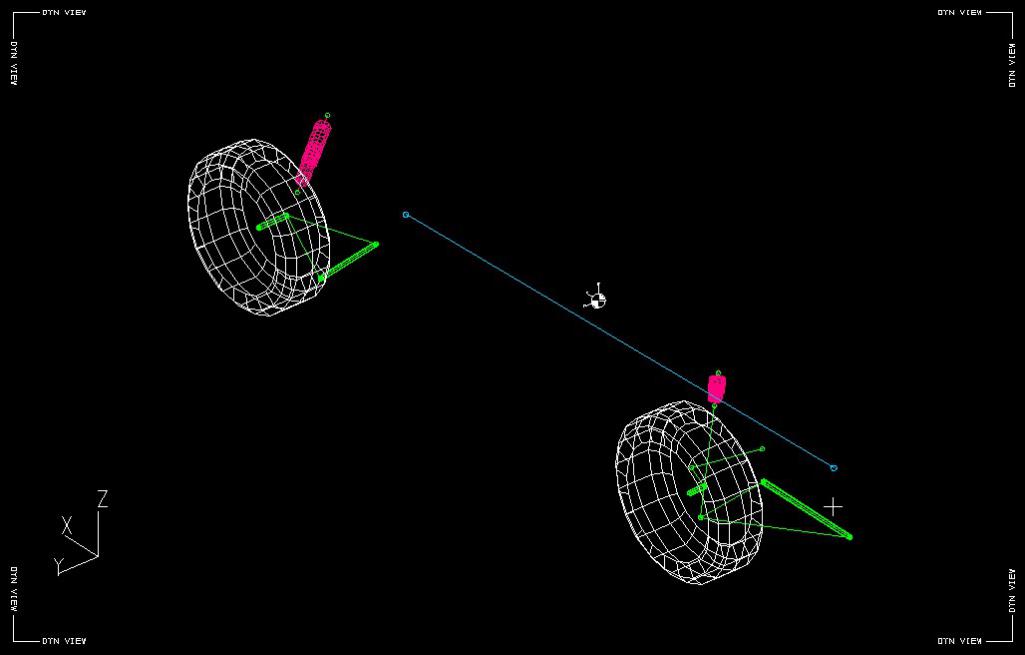 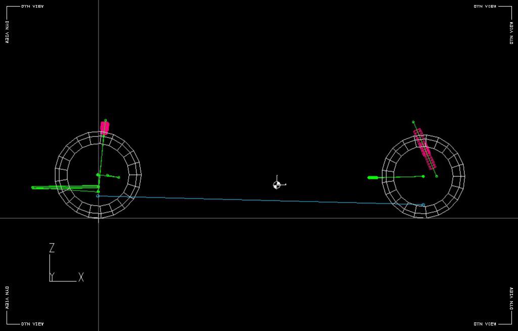 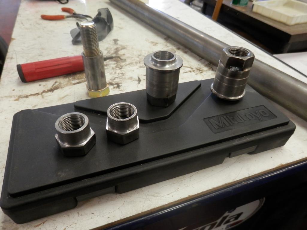 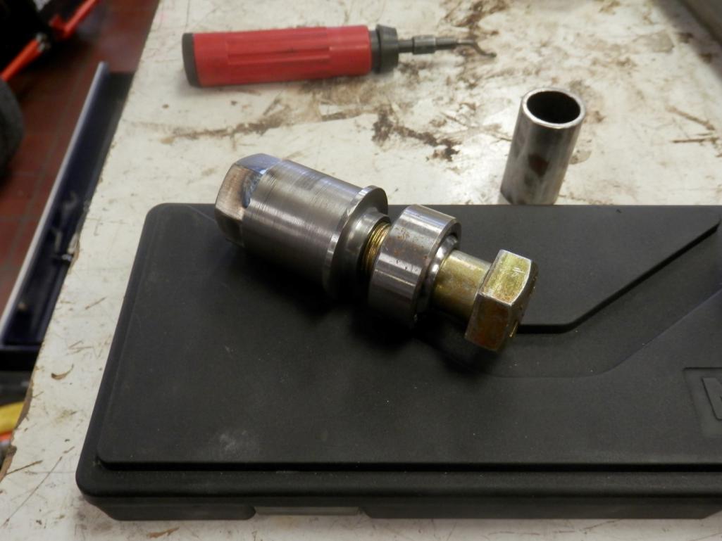 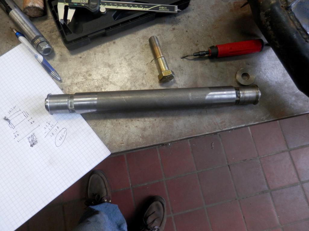 |
|
|
|
|
1 User(s) are reading this topic (1 Guests and 0 Anonymous Users)
0 Members:

|
Lo-Fi Version | Time is now: 23rd April 2024 - 11:52 PM |
Invision Power Board
v9.1.4 © 2024 IPS, Inc.