|
|
|
Porsche, and the Porsche crest are registered trademarks of Dr. Ing. h.c. F. Porsche AG.
This site is not affiliated with Porsche in any way. Its only purpose is to provide an online forum for car enthusiasts. All other trademarks are property of their respective owners. |
|
|

  |

| jd74914 |
 Dec 29 2014, 03:46 PM Dec 29 2014, 03:46 PM
Post
#21
|
|
Its alive  Group: Members Posts: 4,878 Joined: 16-February 04 From: CT Member No.: 1,659 Region Association: North East States |
QUOTE(Racer Chris @ Dec 29 2014, 04:15 PM)  QUOTE(jd74914 @ Dec 29 2014, 04:09 PM) ... , lost my job due to company bankruptcy, ... How convenient for the new company to run out of money so quickly. Previous owner seemed to make it work for the long term. I wondered how you made out when that happened but figured you would land on your feet either way. Yup, there was definitely some funny business there. It's not owned by a Korean company who seems to be in it more for the long run which is good since, while expensive, the product does work well. QUOTE(r_towle @ Dec 29 2014, 04:23 PM) is the car originally green, orange, or yellow? Hahahaha Original color is orange. I thought I wanted a green car so the innards are green and then after seeing it I decided I actually wanted a yellow car. It's slowly getting back to more yellow. Once it's finished this time around everything should be yellow. |
   |

 
|
| jd74914 |
Dec 29 2014, 03:59 PM
Post
#22
|
|
Its alive Group: Members Posts: 4,878 Joined: 16-February 04 From: CT Member No.: 1,659 Region Association: North East States |
The trailing arm mounts were moved up by about 1.8 inches and completely remade. When I took out the old outer mounts 4/6 bolts snapped so remaking them was altogether easier than drilling out the bolts and retapping. At the same time I remade the longitudinal structure.
The longs themselves were redesigned and made taller with slightly different metal thicknesses/layering. This was done to increase the vertical moment of inertial and improve the car's bending stiffness in this area. From a design perspective, the new geometry (more or less 0.5" taller with some strategically sized metal thicknesses) results in a 246% bending stiffness improvement over stock with a stiffness/weight efficiency (in terms of moment of inertia/cross-sectional area) of 4.927e3 mm^4/mm^2 vs the stock efficiency of 4.042e3 mm^4/mm^2. Overall weight increase is about 27 pounds. For reference the Engman kit (best as I can tell since I haven't held one) weights 18 pounds and increases stiffness by 168% assuming an OEM long to start with. You'll note that it will still be double layered with the corrugated inner. The insulated heater tube was removed and a solid tube put in its place. This might get used as a wire tray later. Anywhere there are butted seams there is also a backer lap joint. 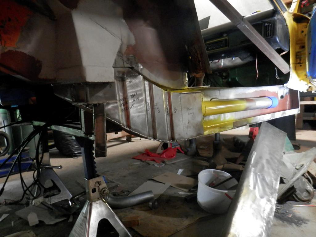 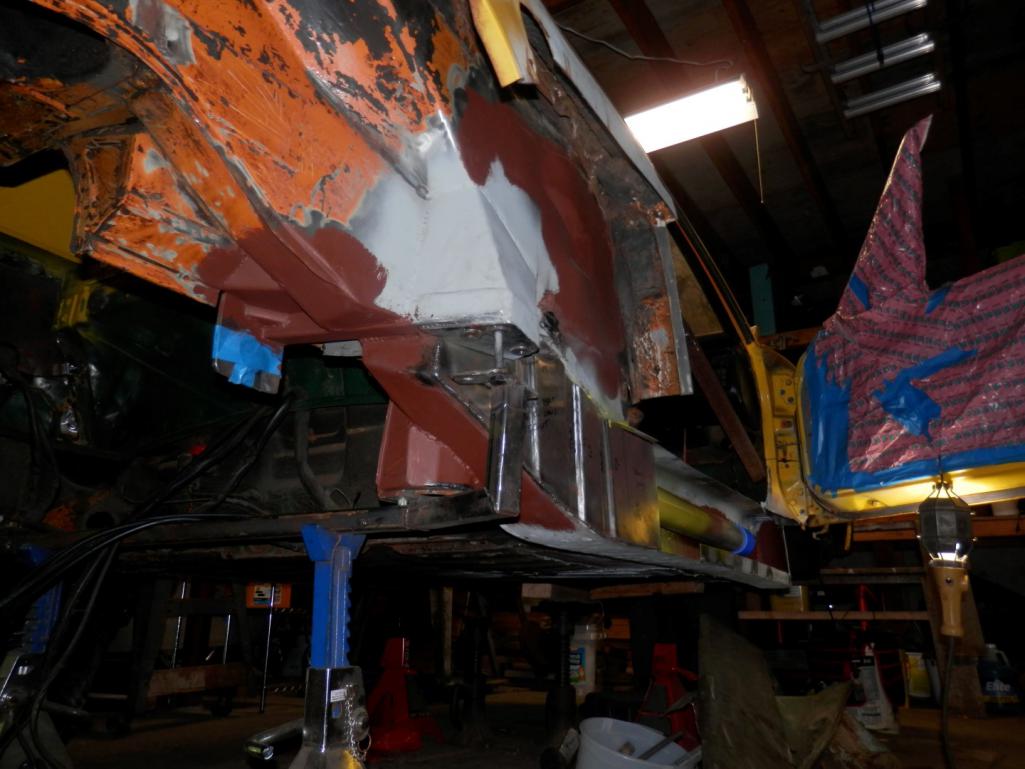 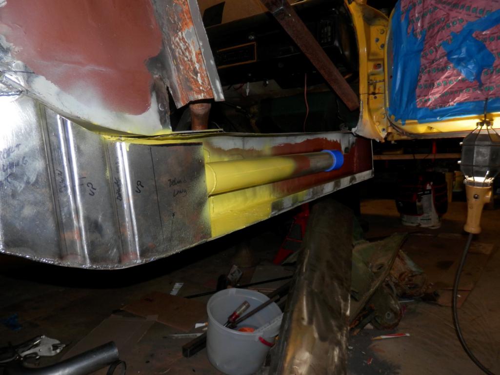 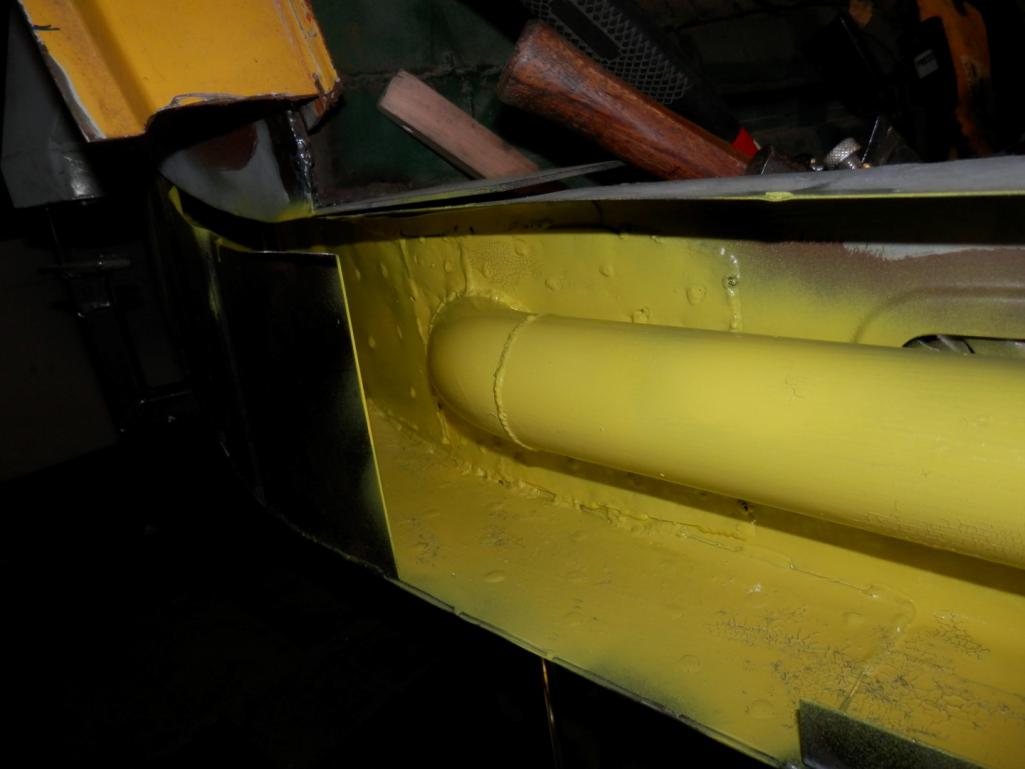 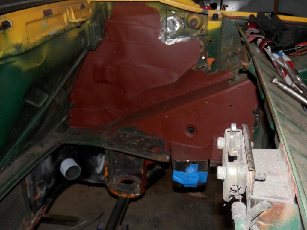 Attached thumbnail(s) 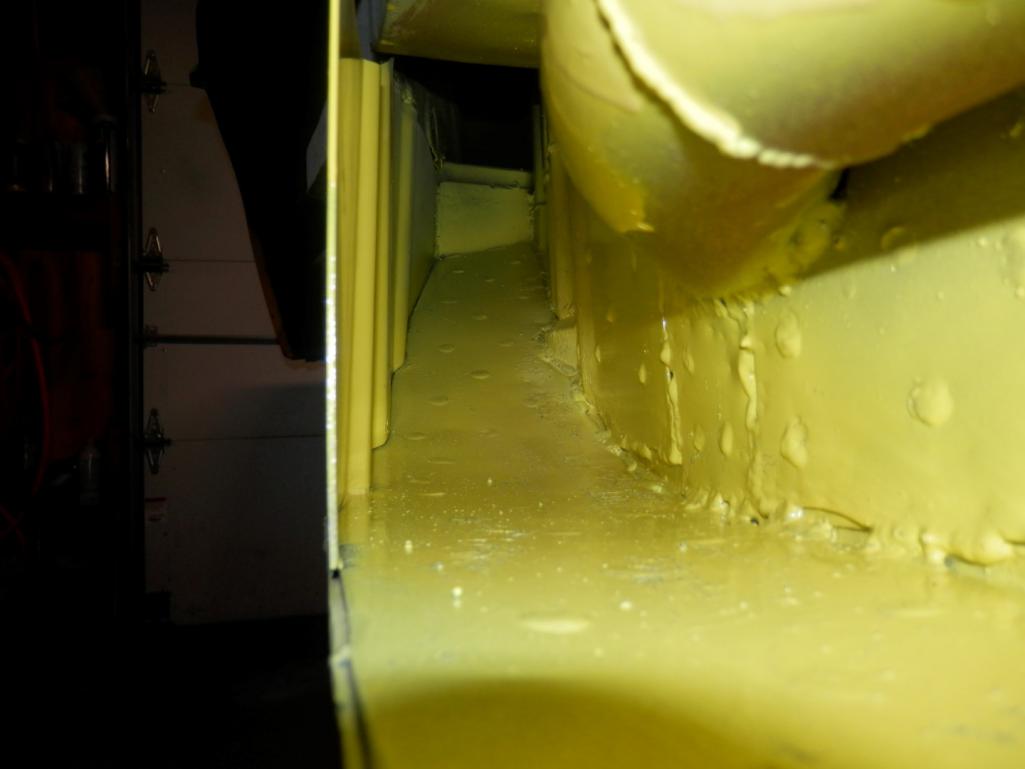
|
|
|
|
| jd74914 |
Dec 29 2014, 04:08 PM
Post
#23
|
|
Its alive Group: Members Posts: 4,878 Joined: 16-February 04 From: CT Member No.: 1,659 Region Association: North East States |
And just for fun some new stuff...
The trigger wheel is from Mario at The Dub Shop and I do need some tender springs. (IMG:style_emoticons/default/smile.gif) 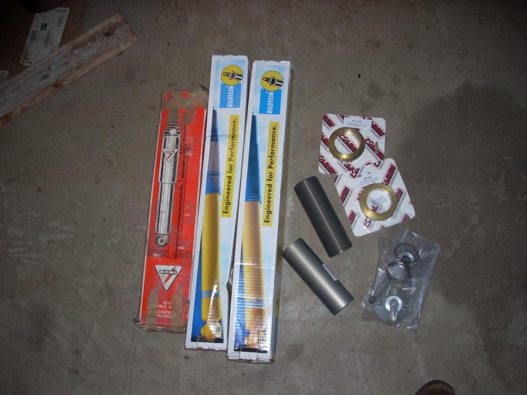 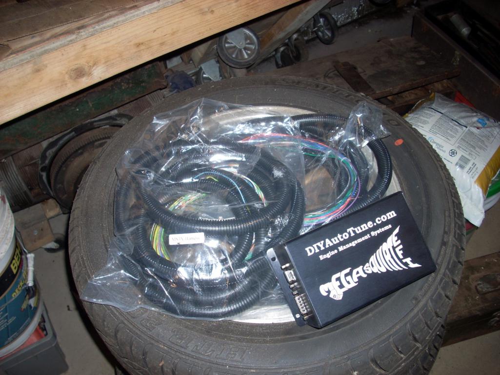 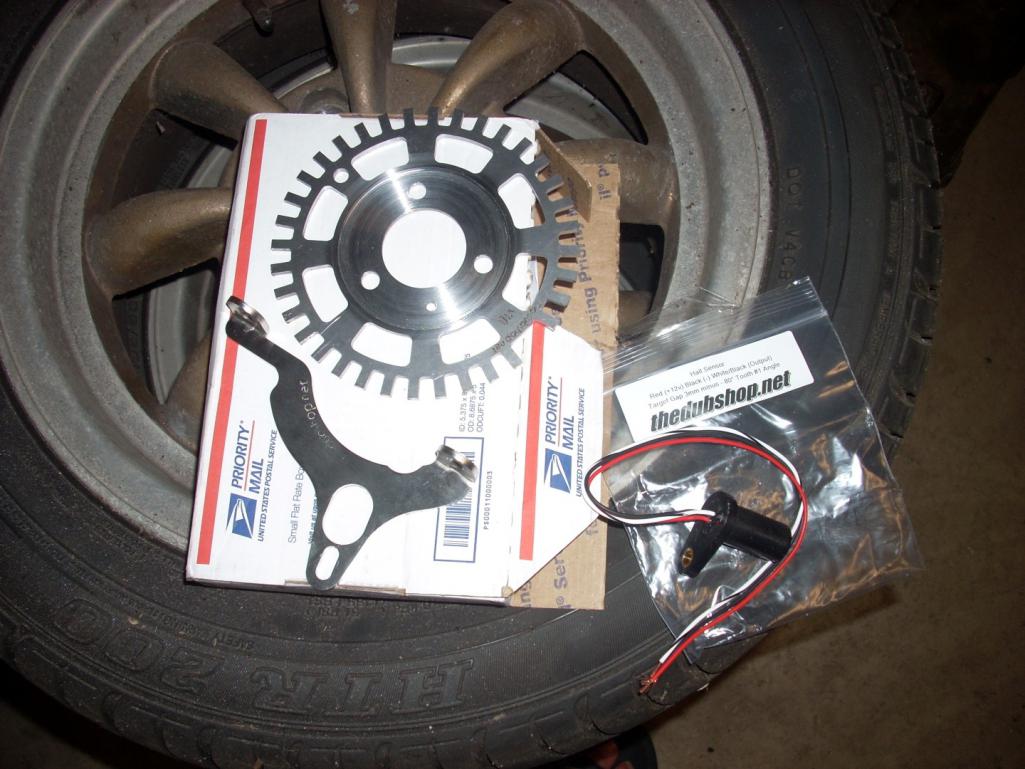 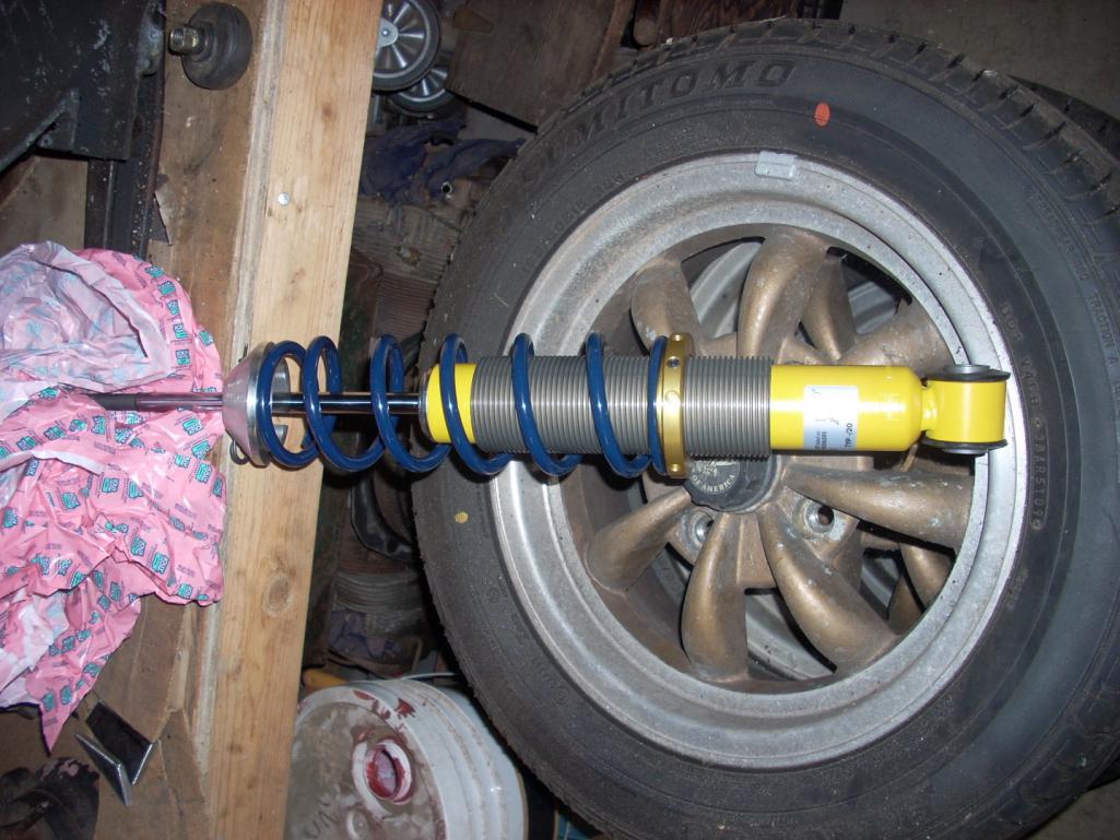 |
|
|
|
| jd74914 |
Dec 29 2014, 04:14 PM
Post
#24
|
|
Its alive Group: Members Posts: 4,878 Joined: 16-February 04 From: CT Member No.: 1,659 Region Association: North East States |
Then chuckc here had a great deal on some phonedials and the suspension to go with them so I just had to go 5-lug. Now the next trick will be raising the spindles on the Bilstein struts and selling the 4-lug raised spindle struts.
That's all I've got! Hopefully the next update will be in far less than a year! (IMG:style_emoticons/default/laugh.gif) 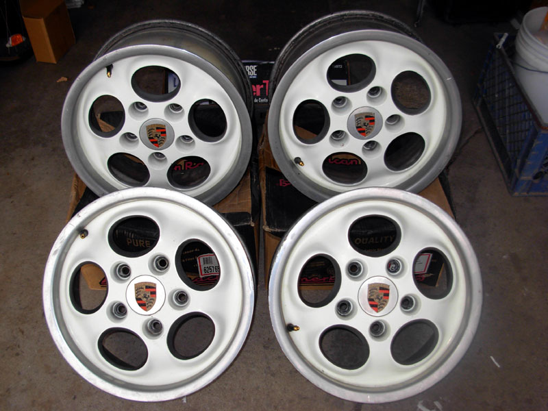 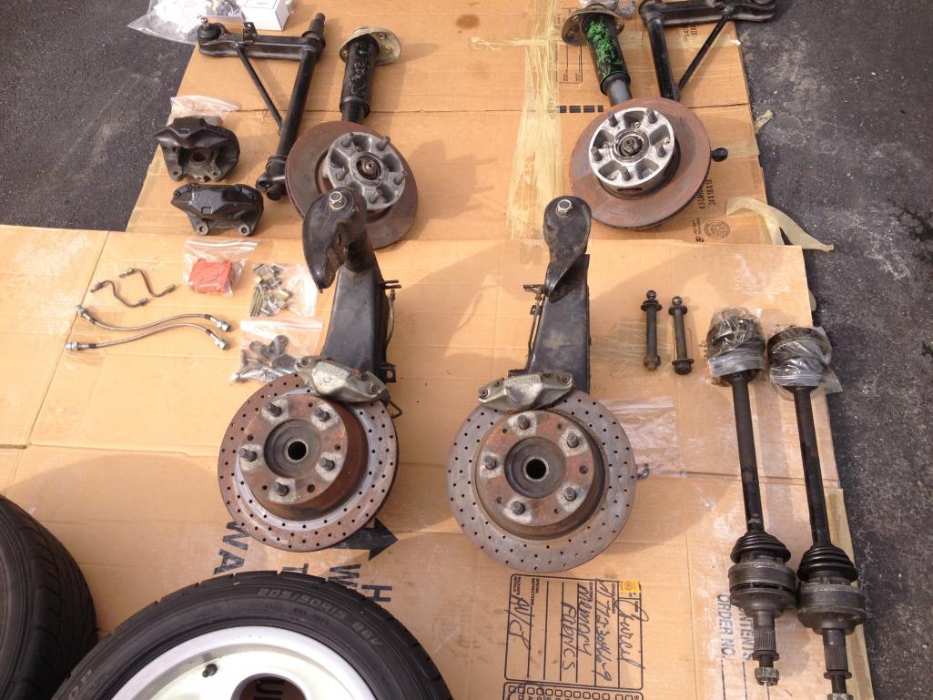 |
|
|
|
| Phoenix914 |
Dec 29 2014, 04:36 PM
Post
#25
|
|
Member Group: Members Posts: 389 Joined: 6-December 06 From: Oviedo, FL Member No.: 7,322 Region Association: South East States |
QUOTE(jd74914 @ Dec 29 2014, 05:14 PM) That's all I've got! Hopefully the next update will be in far less than a year! (IMG:style_emoticons/default/laugh.gif)] I certainly hope so. This is just getting good! (IMG:style_emoticons/default/popcorn[1].gif) |
|
|
|
| jd74914 |
Dec 30 2014, 02:53 PM
Post
#26
|
|
Its alive Group: Members Posts: 4,878 Joined: 16-February 04 From: CT Member No.: 1,659 Region Association: North East States |
QUOTE(Phoenix914 @ Dec 29 2014, 05:36 PM) I'll try! Quick exploded view of the new trailing arm inner features so they might make more sense (couldn't find the models yesterday night). 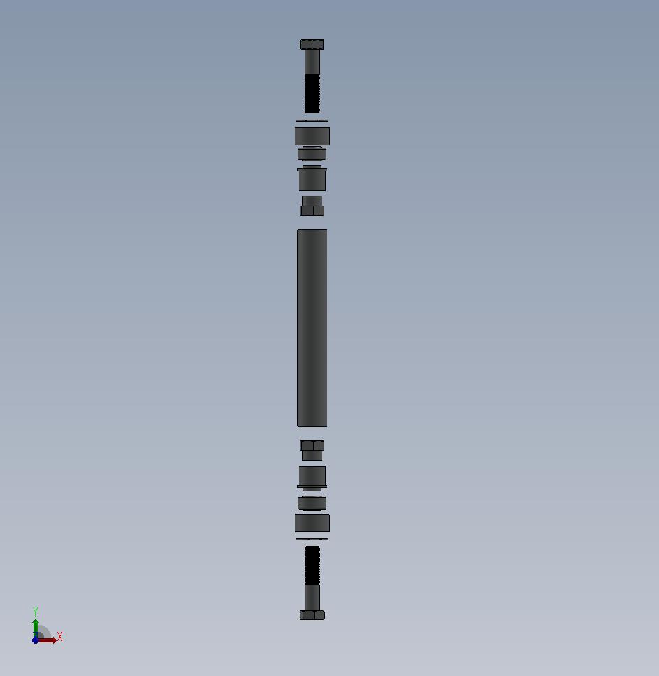 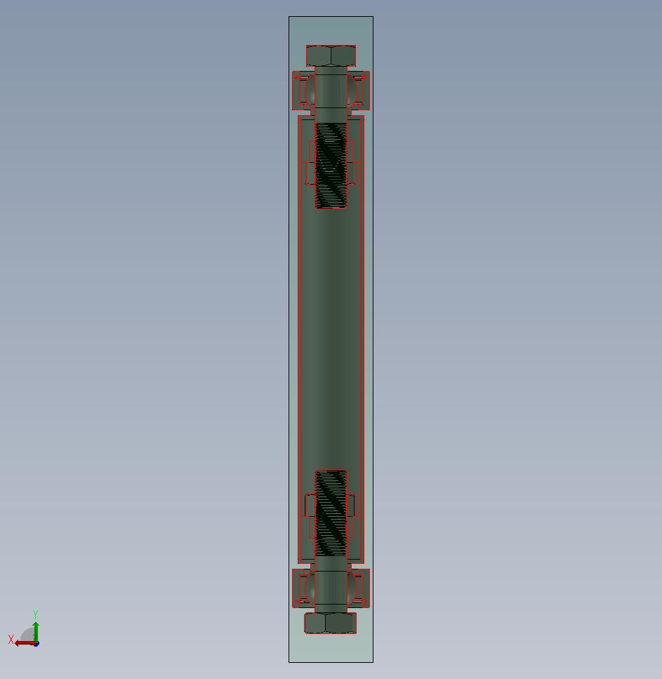 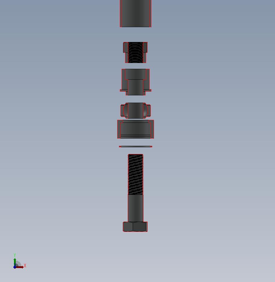 |
|
|
|
| Chris Pincetich |
Dec 30 2014, 03:35 PM
Post
#27
|
|
B-) Group: Members Posts: 2,082 Joined: 3-October 05 From: Point Reyes Station, CA Member No.: 4,907 Region Association: Northern California |
Curious about that trailing arm inner and your strategy for the end bolts. Are they torqued down super tight? Did you keep them "loose" and use locktite on the threads?
The reason I ask I my set-up, and it's propensity to get loose. I have an aftermarket roller bearing trailing arm pivot and it is secured on both ends by bolts like yours. They get a little loose, so I just re-tighten them....but soon will get in there to re-grease and rehab and likely coat the threads w some sort of locktite. Great work and impressive math (IMG:style_emoticons/default/beerchug.gif) |
|
|
|
| jd74914 |
Dec 31 2014, 11:36 AM
Post
#28
|
|
Its alive Group: Members Posts: 4,878 Joined: 16-February 04 From: CT Member No.: 1,659 Region Association: North East States |
QUOTE(Chris Pincetich @ Dec 30 2014, 04:35 PM) Curious about that trailing arm inner and your strategy for the end bolts. Are they torqued down super tight? Did you keep them "loose" and use locktite on the threads? The reason I ask I my set-up, and it's propensity to get loose. I have an aftermarket roller bearing trailing arm pivot and it is secured on both ends by bolts like yours. They get a little loose, so I just re-tighten them....but soon will get in there to re-grease and rehab and likely coat the threads w some sort of locktite. I'm planning on torquing them down normally and possibly using just a little loctite tape on the threads (and lot of anti-seize on the shank). I'd be a little afraid of using too much loctite because any corrosion also adds to the locking effect and it would be a shame to have to drill out big bolts. One of the reasons I didn't like the needle bearing kits is that I couldn't see any way for them to allow misalignment on the inside ear. When you bolt the outer side to the piece that lets you adjust toe the bearing lines up nicely and won't cause any loosening if there is a little bit of bind. The ear is fixed however, and at least the kits I've seen didn't seem to have anything in there to allow for misalignment. I might be wrong, but I've always figured that the misalignment where wouldn't allow the bolts to stay tight or promote even thrust bearing wear. In my setup, the bolting point in the ear can pivot as it's a spherical bearing, so you're always bolting exactly perpendicular to the bearing if that makes sense. I could be totally wrong, so take that with a grain of salt, but that was my rationale for going this way and not building with needle bearings. If this doesn't work I've been thinking I'll put a needle nearing setup together with misalignment washers to allow bolting perfectly normal to the thrust surface. |
|
|
|
| FourBlades |
Dec 31 2014, 11:45 AM
Post
#29
|
|
From Wreck to Rockin Group: Members Posts: 2,056 Joined: 3-December 07 From: Brevard, FL Member No.: 8,414 Region Association: South East States |
|
|
|
|
| Mueller |
Dec 31 2014, 01:39 PM
Post
#30
|
|
914 Freak! Group: Members Posts: 17,155 Joined: 4-January 03 From: Antioch, CA Member No.: 87 Region Association: None |
Great progress.....
Have you considered using misalignment washers on the bolts? Misalignment washers If you want to play with and experiment with a needle bearing for cheap, pay shipping and I'll send you an old unused Nadella bearing that was left over from when I used to make the kits. 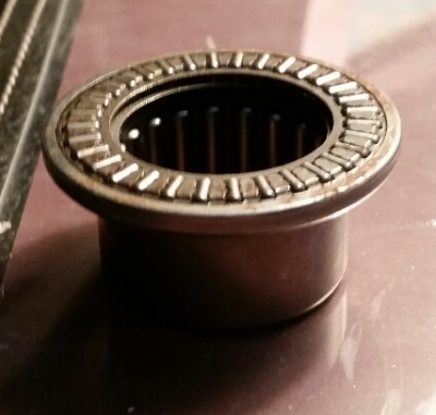 |
|
|
|
| yeahmag |
Dec 31 2014, 03:25 PM
Post
#31
|
|
Advanced Member Group: Members Posts: 2,483 Joined: 18-April 05 From: Pasadena, CA Member No.: 3,946 Region Association: Southern California |
Andy and I talked about this a bit. The problem is the misalignment washers are really quite thick. Would need to rengineer the kit to accommodate them.
|
|
|
|
| Jeff Hail |
Dec 31 2014, 06:58 PM
Post
#32
|
|
Senior Member Group: Members Posts: 1,141 Joined: 3-May 07 From: LA/ CA Member No.: 7,712 |
The inner ear will bend/deflect a little bit when adjusting toe. Trust me.
I like those pivot shafts! |
|
|
|
| jeff |
Dec 31 2014, 10:52 PM
Post
#33
|
|
Member Group: Members Posts: 256 Joined: 17-January 04 From: thousand oaks,ca Member No.: 1,570 |
This setup should eliminate the bind when adjusting rear toe...
 |
|
|
|
| jd74914 |
Jan 1 2015, 01:09 PM
Post
#34
|
|
Its alive Group: Members Posts: 4,878 Joined: 16-February 04 From: CT Member No.: 1,659 Region Association: North East States |
QUOTE(FourBlades @ Dec 31 2014, 12:45 PM) Awesome job rebuilding the long! Thanks! QUOTE(Mueller @ Dec 31 2014, 02:39 PM) If you want to play with and experiment with a needle bearing for cheap, pay shipping and I'll send you an old unused Nadella bearing that was left over from when I used to make the kits. That would be awesome! PM sent! (IMG:style_emoticons/default/smile.gif) QUOTE(yeahmag @ Dec 31 2014, 04:25 PM) Andy and I talked about this a bit. The problem is the misalignment washers are really quite thick. Would need to rengineer the kit to accommodate them. Looking at it there really isn't much room in there unless you grind off part of the control arm not a bid deal, or recess the shafts into the arm. I went this way mostly for cost since everything is new anyways. Even good spherical bearings are pretty cheap compared to the Nadella rollers. QUOTE(Jeff Hail @ Dec 31 2014, 07:58 PM) The inner ear will bend/deflect a little bit when adjusting toe. Trust me. I like those pivot shafts! Interesting...I wish I had looked more closely when pulling everything off. Thanks Jeff! I'm hoping I can pull this off with a level of quality near your car's! QUOTE(jeff @ Dec 31 2014, 11:52 PM) This setup should eliminate the bind when adjusting rear toe... Yep, mine is quite similar to that on the frame side. used bearing cups from UB Machine because I didn't really feel like machining customs ones. The main difference between that setup and mine is that I didn't weld threaded bushings straight into the trailing arm and instead pressed in an assembly to ensure co-linearity. |
|
|
|
| jd74914 |
Jan 9 2015, 07:05 PM
Post
#35
|
|
Its alive Group: Members Posts: 4,878 Joined: 16-February 04 From: CT Member No.: 1,659 Region Association: North East States |
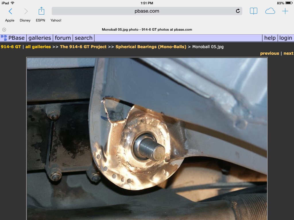
A few more pieces. I seam welded the trailing arm mounts and then machined 1.75" holes in them for my spherical bearing housings. I screwed up on the first one by not machining an insert to help it hold shape with all of the heat and warped it a bit which required a little honing. After making that mistake I turned an aluminum piece to pull heat out of the housing which seemed to work well. We'll see how the slightly out-of-round housing works out. The bearing pressed in OK, but I think I might make another one since we don't have a shortage of suspension mounts. (IMG:style_emoticons/default/laugh.gif)
Unfortunately the final product picture is blurry, but I think you can get the idea. I just found the last picture and thought it was cool so I added it. It's of the bottom of the gas tank in a '58 John Deere 420C bulldozer which I clearanced to fit a taller battery for Father's Day. 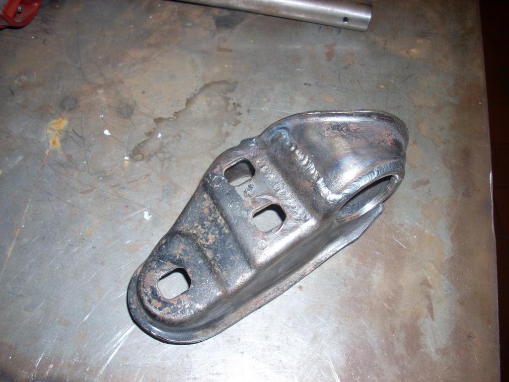 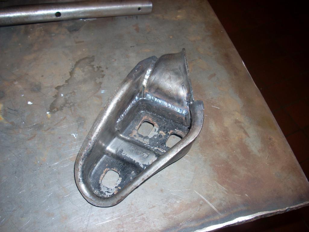 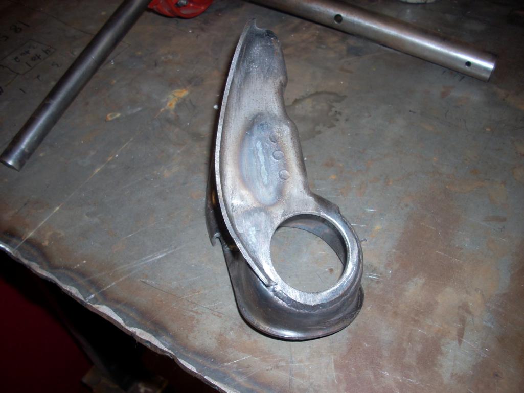 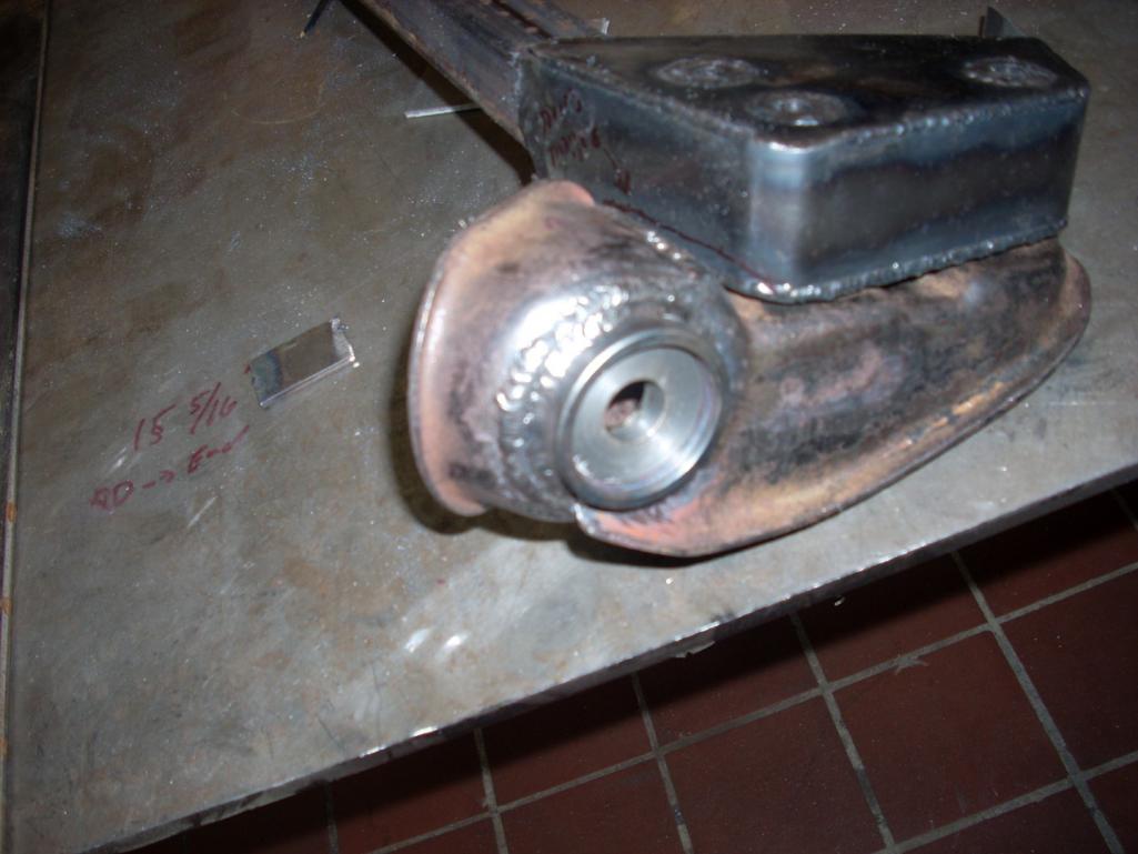 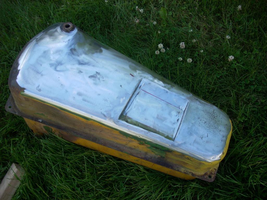 |
|
|
|
| jd74914 |
Jan 9 2015, 08:17 PM
Post
#36
|
|
Its alive Group: Members Posts: 4,878 Joined: 16-February 04 From: CT Member No.: 1,659 Region Association: North East States |
Forgot to add this in the last post...
Those trailing arm brackets are really tough stuff. I'm guessing they are made of 41xx series steel since I tried cutting one pretty slowly with a hole saw and wasted the hole saw even using lots of oil. Mild steel parts don't tend to do that. A carbide cutter on the mill worked much better. (IMG:style_emoticons/default/laugh.gif) For anyone thinking of seam welding them they also weld really nicely (definitely cold rolled)! |
|
|
|
| veekry9 |
Jan 9 2015, 08:46 PM
Post
#37
|
|
OldMember Group: Retired Members Posts: 3,068 Joined: 17-June 13 From: TO Member No.: 16,025 Region Association: Canada |
I missed this thread last year as I was off on other pursuits and have just now discovered this build.
We were/are using the sls technique to create lost foam patterns for small production runs of exotic metal castings. The FormulaSAE racer is a jewel,well done. The pertinent specification of interest to me was the torsional stiffness of the chassis. Now the arduous journey begins,the sheetmetal repair of the 914 and the skilled application of lightweight reinforcement. Q The longs themselves were redesigned and made taller with slightly different metal thicknesses/layering. This was done to increase the vertical moment of inertial and improve the car's bending stiffness in this area. From a design perspective, the new geometry (more or less 0.5" taller with some strategically sized metal thicknesses) results in a 246% bending stiffness improvement over stock with a stiffness/weight efficiency (in terms of moment of inertia/cross-sectional area) of 4.927e3 mm^4/mm^2 vs the stock efficiency of 4.042e3 mm^4/mm^2. Overall weight increase is about 27 pounds. For reference the Engman kit (best as I can tell since I haven't held one) weights 18 pounds and increases stiffness by 168% assuming an OEM long to start with. You'll note that it will still be double layered with the corrugated inner. The insulated heater tube was removed and a solid tube put in its place. This might get used as a wire tray later. Anywhere there are butted seams there is also a backer lap joint. Q Yeah,this is what I like,the deepening of the cross section of the longs,the use of corrugated rather than flat sheetmetal panels. That you are placing them internally is brilliant and never occurred to me,looking from the outside of my pristine longs. I'm going to use that idea as it's a great solution to the flexi flyer characteristics of the floorpan. A stiff perimeter monocoque ala 904,not outside the box,inside.Terrific. Some of this may be of interest to you as no doubt you're proficient in the use of cae software. https://www.rhino3d.com/ http://www.cimsystem.com/ http://www.mastercam.com/en-us/ http://www.caelinux.com/CMS/ |
|
|
|
| jd74914 |
Sep 14 2015, 07:46 AM
Post
#38
|
|
Its alive Group: Members Posts: 4,878 Joined: 16-February 04 From: CT Member No.: 1,659 Region Association: North East States |
Finally did a little more work this weekend after a long hiatus with a lot of work, an almost move to KY, and a bunch of other people's projects in between.
I've been spoiled by working on cars that don't require welding or painting upside down and decided to build a rotisserie to reduce the amount of overhead welding on all of the suspension mounts. This time around the whole bottom will be stripped, repainted, and undercoated which will also be nicer to do on a side. My goal is to make a quick and dirty one to not take much time away from the overall car build so I'm modifying 2 cheap engine stands to do the job. They don't have pivot bearings so hopefully the car won't be too hard to turn, but I guess I'll cross that bridge in a few weeks when loading it on. To try and avoid having the longest car build ever I'm trying to spend at least half a weekend day per week working just to make a little progress. (IMG:style_emoticons/default/laugh.gif) -------- First step was to cut apart the vertical leg, add about a foot of metal. This results in a pivot-to-bottom brace height of 38", giving about 3" of safety factor from the widest point of the car to brace. The pivot also needed to be made parallel to the bracing as the engine stand was tilted non-parallel. Next was to repeat the modifications on the second engine stand leg. After a whole bunch of hack fixture and a bit of welding the second stand was done too. Note that (2) pieces of 1.375" square x 0.1875 wall steel were used since I didn't have any of the correct 1.5x3x0.100" box beam. It should be plenty strong enough for a light car though. 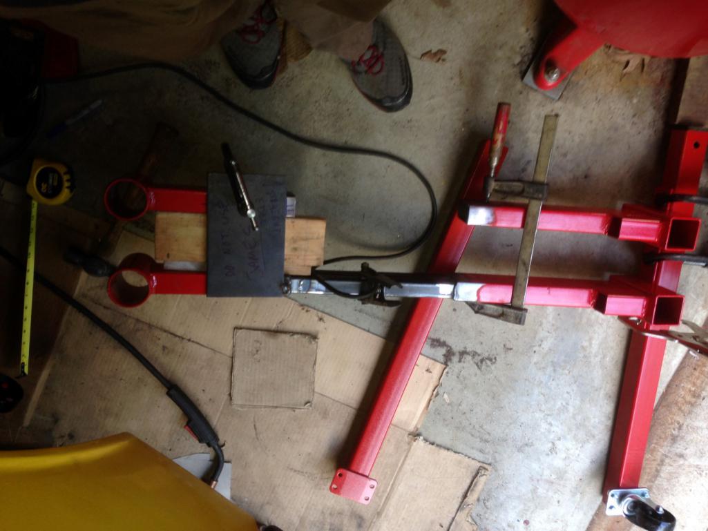 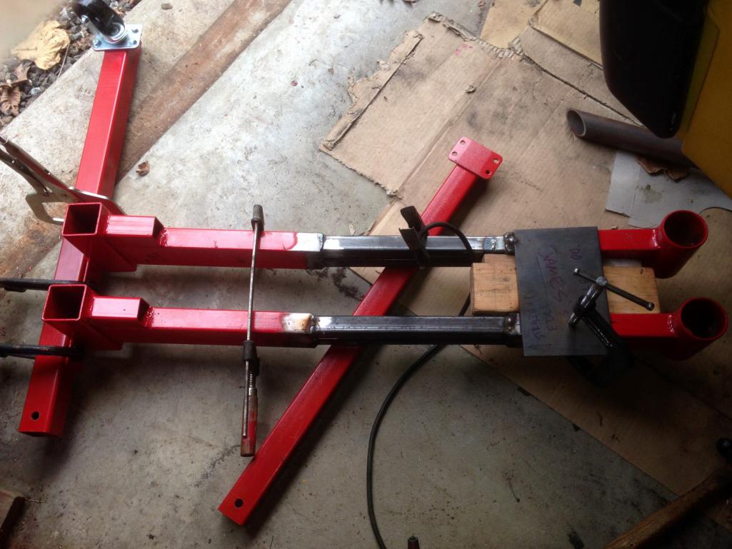 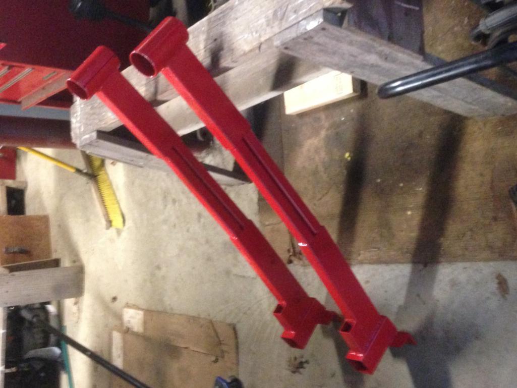 Next week's goal is to get metal to make the arms to attach to the bumper mounts, some cross bracing, and connect the 2 stands under the car. (IMG:style_emoticons/default/smile.gif) |
|
|
|
| jd74914 |
Oct 31 2016, 06:37 PM
Post
#39
|
|
Its alive Group: Members Posts: 4,878 Joined: 16-February 04 From: CT Member No.: 1,659 Region Association: North East States |
October 2016 Update:
Not much got done this month due to school commitments. I did get time to clean off the car and start organizing parts. Yesterday I also got the intake manifold assembly off of the LGT motor, removed the TGVs and started removing all of their parts in preparation for gutting them. I'm going to be removing the throttling valves and welding up the throttle shaft ports in the coming weeks. Pictures coming soon. This picture is stolen off the web, but essentially the end goal of the TGV delete. 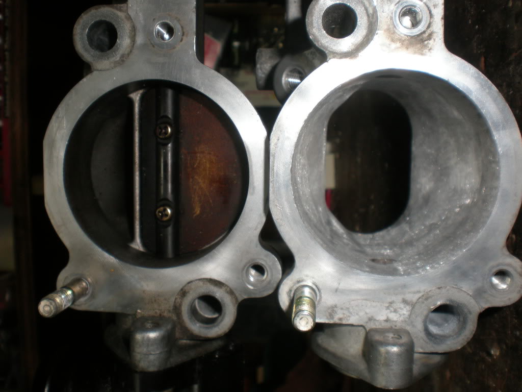 Additionally, I started designing the mounts and arms for the new sway bar. It's a NASCAR bar from HRP. Before deciding on the final arm length, I wanted to check the effective installed motion ratio to understand at what point further adjustment is useless. Some initial basic calculations indicate that an 8" arm length is enough, but the actual travel math is relatively complicated since the control and bar arms move in different planes. To solve this I added the bar into my suspension kinematics model, but unfortunately the effective motion ratio is a bit harder to pull out than I thought it would be. Results TBD. (IMG:style_emoticons/default/smile.gif) 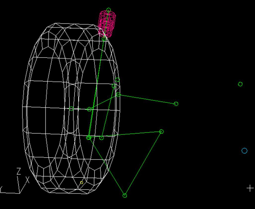 |
|
|
|
| jd74914 |
Nov 12 2016, 05:18 PM
Post
#40
|
|
Its alive Group: Members Posts: 4,878 Joined: 16-February 04 From: CT Member No.: 1,659 Region Association: North East States |
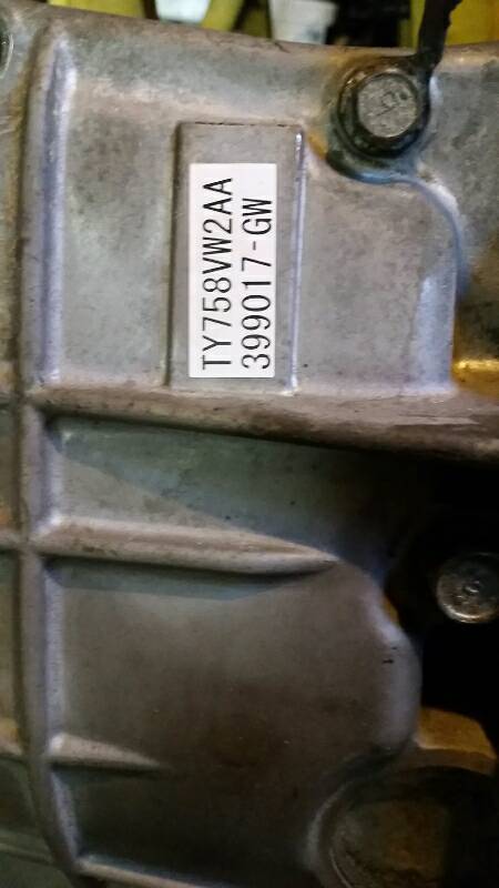
I picked up a gearbox off Craigslist this week. It's out of a 2012 WRX and has ~30k miles (the car was wrecked). It bench shifts smoothly and is super clean so I'm hoping that it isn't messed up inside, but I guess we'll see when the center diff comes out.
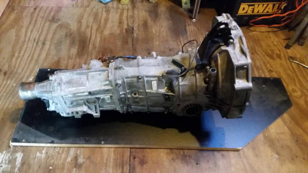  I've got feelers out now for a broken central diff in the local area so I don't have to ruin this one making a locker if it's in good shape. Good ones seem to go for $200-350 on NASIOC so selling this one would go pretty far in offset the overall transmission cost. Anyone here have a broken diff they'd be willing to let go for cheap? (IMG:style_emoticons/default/laugh.gif) (IMG:style_emoticons/default/biggrin.gif) The 2008-2014 WRX transmissions seem to be pretty stout units. Some threads on the Subie forums show their gear widths are greater than the early WRX transmissions and the case castings seem to be a little beefier too. Unfortunately, around here at least they are a bit more expensive than the older push-clutch Legacy, Impreza, etc. stuff. Right out of the box the gear ratios appear pretty well matched, though even with the 3.900 front diff first gear seems a little bit low. Ideal 1st gear is from an STi RA but those gears/main-shafts are super rare and priced accordingly. The plot below shows tractice force, or the actual power put through the tires into the ground, vs. vehicle speed for the 08-14 WRX transmission. It assumes a perfectly stock '05 Legacy GT power output (shown in the second plot). In terms of pure acceleration and drive efficiency, you want this curve to have a parabolic shape. The parabolic shape means that power to the ground is constant and at its maximum. As mentioned before, 1st is a little bit low, but it's going to stay that way forever probably. (IMG:style_emoticons/default/laugh.gif) The easiest way to make the in-gear traction numbers fit the overall traction parabola better is to shift the engine powerband up slightly and increase torque in the 4100-4600 rpm range. With some AVCS and boost tuning this shouldn't be too difficult. (IMG:style_emoticons/default/sunglasses.gif) One other thing to note is the red "max tractive force" line. This line is the most force the tires can handle and still retain traction. It's a pretty simplistic calculation just using CG, wheelbase, and an assumed single tire coefficient of friction which then calculates dynamic driving wheel weight and from that max sustainable tractive force. The number isn't correct since I'm just guessing CG, weight, etc. The tire friction coefficient is pretty questionable since I've never seen one for street tires (only slicks) and the fact that it's not taking into rotation speed or any lateral forces added by the suspension kinematics. It is useful to basically know first gear and the start of second are really just for burnouts! (IMG:style_emoticons/default/laugh.gif) The spreadsheet used for these calculations is attached is anyone wants to play with it. No guarantees on accuracy, though I believe everything is correct. The format was borrowed from something posted a long time ago on Pelican Parts by B. Smith (IIRC, unfortunately I never wrote down the source), but has been modified extensively. You can add different gear ratios in, I just only put in some common stuff. Check out the last page for some Subaru transmission information if you want to play around with different gears not listed in the list or personalize it to your transmission. 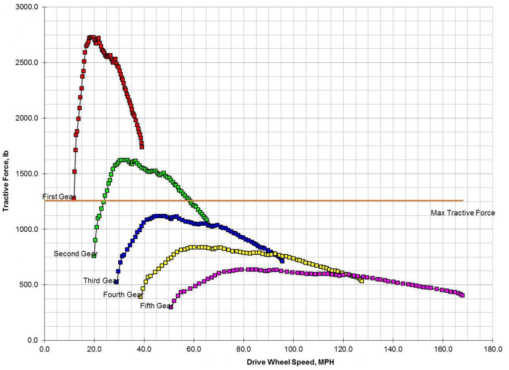 Stock dyno plot (not mine, just from a local eddy current dyno) 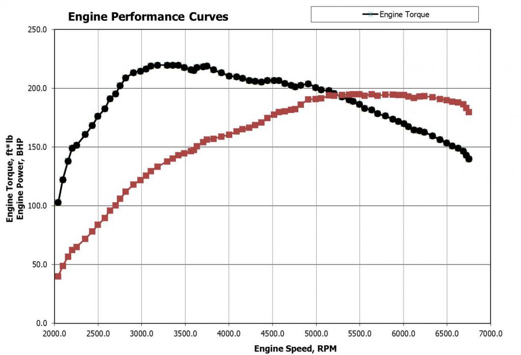 |
|
|
|
|
1 User(s) are reading this topic (1 Guests and 0 Anonymous Users)
0 Members:

|
Lo-Fi Version | Time is now: 26th May 2026 - 09:44 PM |
Invision Power Board
v9.1.4 © 2026 IPS, Inc.