|
|
|
Porsche, and the Porsche crest are registered trademarks of Dr. Ing. h.c. F. Porsche AG.
This site is not affiliated with Porsche in any way. Its only purpose is to provide an online forum for car enthusiasts. All other trademarks are property of their respective owners. |
|
|

  |

| jd74914 |
 Nov 12 2016, 05:22 PM Nov 12 2016, 05:22 PM
Post
#41
|
|
Its alive  Group: Members Posts: 4,878 Joined: 16-February 04 From: CT Member No.: 1,659 Region Association: North East States |
Ok, I guess the spreadsheet add doesn't work for .xlsm
It's attached in a .zip format so anyone who wants to try it will have to unzip it before using. Attached File(s)  PORSCHE_914_SUBARU_DRIVETRAIN_CALC_A.zip ( 1.32mb )
Number of downloads: 76
PORSCHE_914_SUBARU_DRIVETRAIN_CALC_A.zip ( 1.32mb )
Number of downloads: 76 |
   |

 
|
| 914forme |
Nov 13 2016, 06:21 PM
Post
#42
|
|
Times a wastin', get wrenchin'! Group: Members Posts: 3,899 Joined: 24-July 04 From: Dayton, Ohio Member No.: 2,388 Region Association: None |
QUOTE(jd74914 @ Oct 31 2016, 07:37 PM)  Additionally, I started designing the mounts and arms for the new sway bar. It's a NASCAR bar from HRP. Before deciding on the final arm length, I wanted to check the effective installed motion ratio to understand at what point further adjustment is useless. Some initial basic calculations indicate that an 8" arm length is enough, but the actual travel math is relatively complicated since the control and bar arms move in different planes. To solve this I added the bar into my suspension kinematics model, but unfortunately the effective motion ratio is a bit harder to pull out than I thought it would be. Results TBD. (IMG:style_emoticons/default/smile.gif) really love what your doing but over complicating it a bit. The distance front the bar center to the center above the A-Arm is your ideal location since th pivots move in multiple plains. Then you are "stuck" with the number of degrees the amounts will allow your bars to travel with out binding over the range of the suspension. two points in a cad drawing will not tell you that, real world will. This of course is based on the factory U tab on the arms, and a double sheer tab up top running a set of rod ends for the drop links. If you are using a spherical bearing on the arm, or a different high angle mount, then your movement can be greater. Looking forward to seeing your solution to the Nascar bar mounts. I know I gave lots of thought to mine before I said (IMG:style_emoticons/default/WTF.gif) and just did it! Best solution (IMG:style_emoticons/default/confused24.gif) I do know they do not bind with bar rotation. |
|
|
|
| jd74914 |
Dec 20 2016, 10:46 AM
Post
#43
|
|
Its alive Group: Members Posts: 4,878 Joined: 16-February 04 From: CT Member No.: 1,659 Region Association: North East States |
I got a sweet set of single adjustable JRZ shocks for the rear from Stephen (914forme). (IMG:style_emoticons/default/smile.gif)
They take 2.25" springs-my old shocks took 2.5" so I'll need to get some new springs. The rod-end spring perches are pretty nice in that they fit to the eyelet. The trailing arm attachment bolt is a pretty nice piece as well. These should work well with the raised "stock" shock console I'm planning. Notes for later: Perch thread dimension is said to be M52x1.5. That is incorrect because the major diameter of the threads is ~2.1565 vs 2.046" (51.97 mm) it should be for that thread. 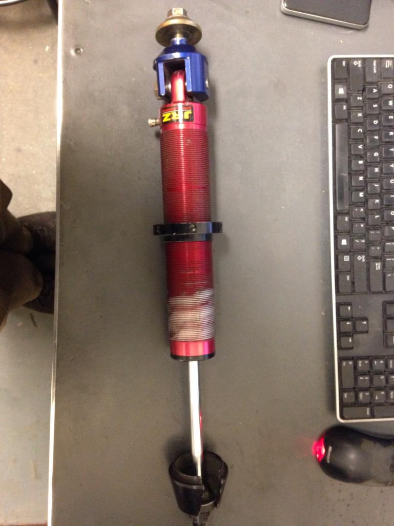 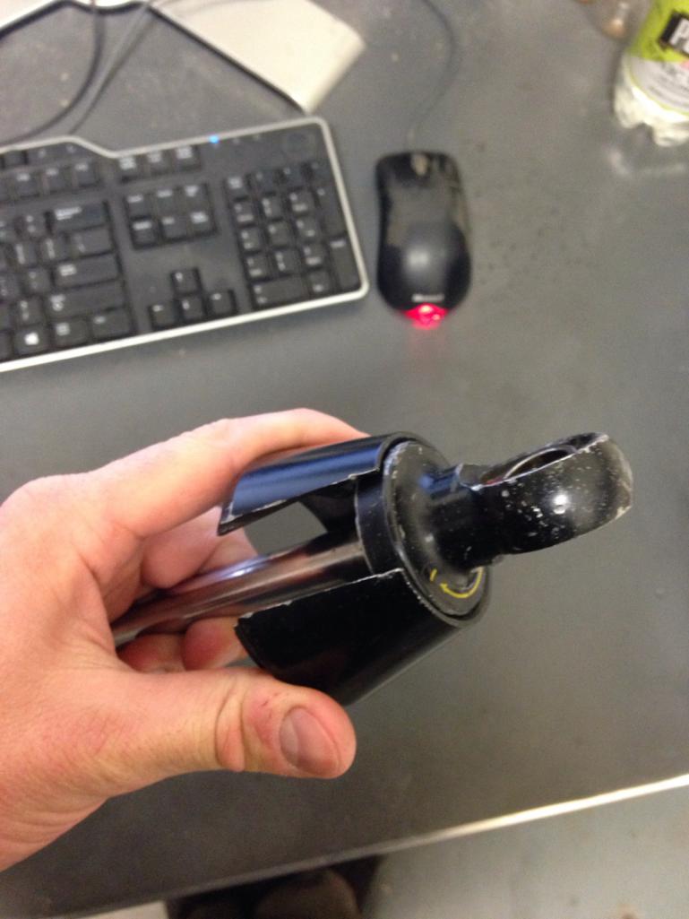 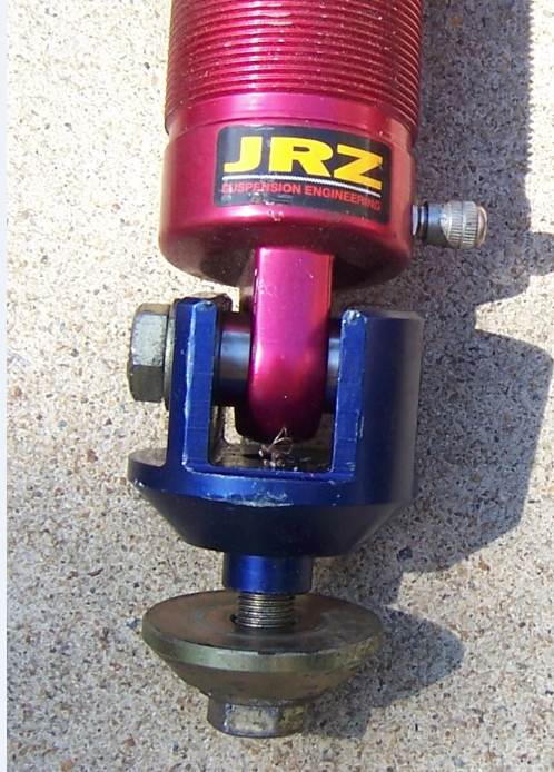 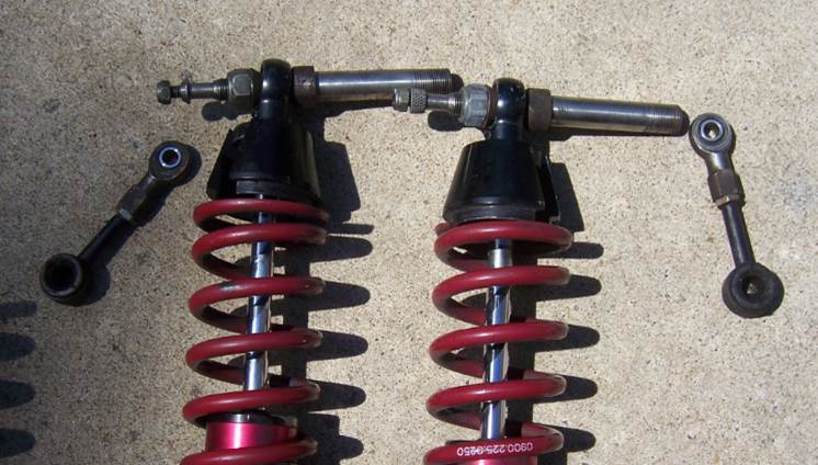 This morning I turned down some 6061 spring spacers so I can run a zero-weight helper spring and avoid having the main spring come off the perches when the car gets jacked up. The smaller lip is for the helper spring and larger for the main coil. These are going into the pile for anodizing now. 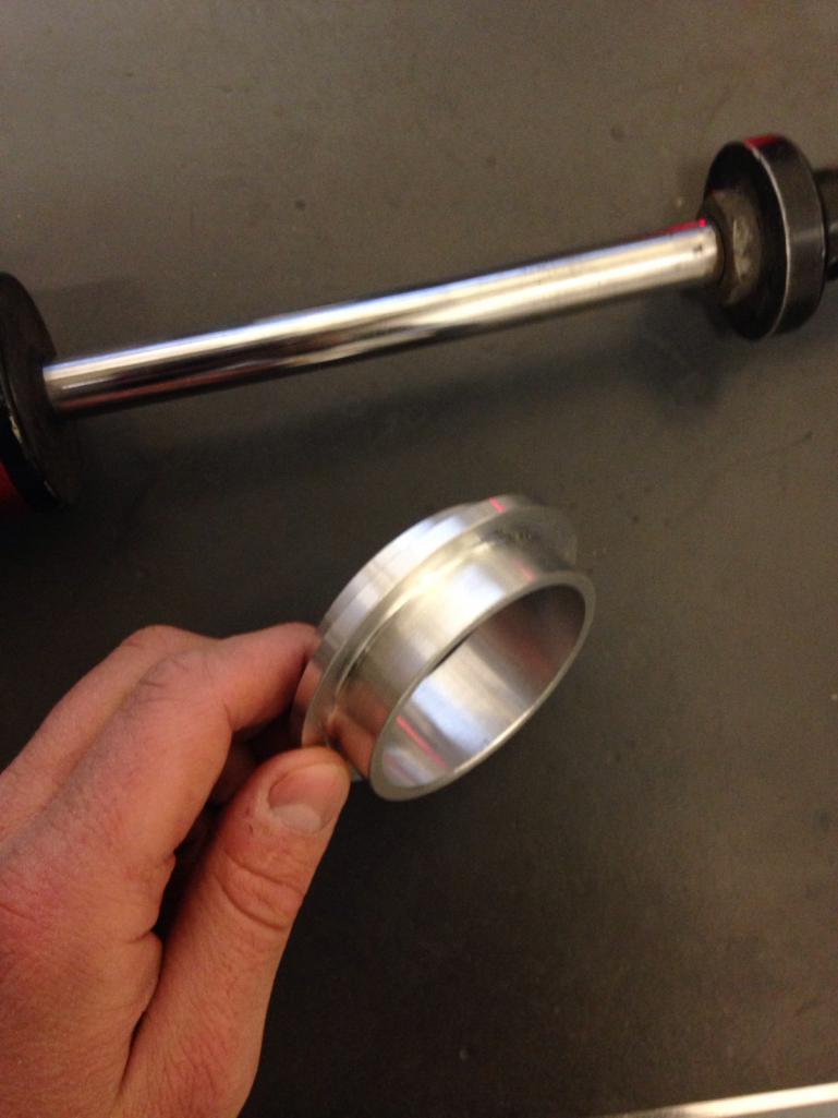 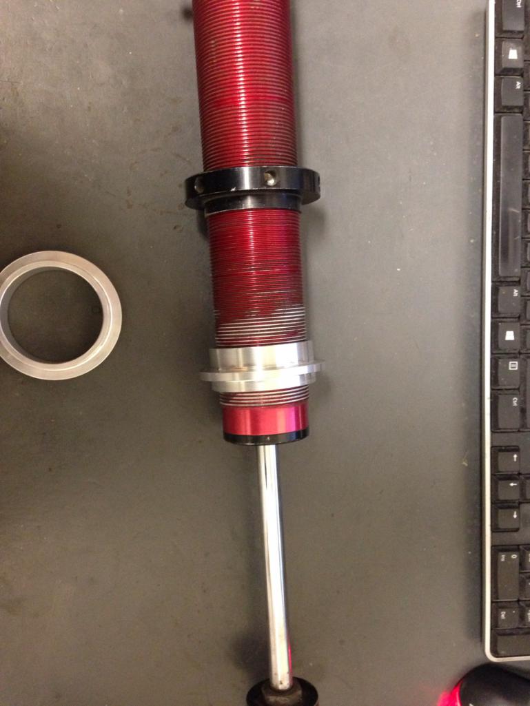 |
|
|
|
| jd74914 |
Dec 20 2016, 11:10 AM
Post
#44
|
|
Its alive Group: Members Posts: 4,878 Joined: 16-February 04 From: CT Member No.: 1,659 Region Association: North East States |
Also pulled the intake wiring harness off. With all of the zip ties and hard to get to connectors, it was a bit of a pain. I didn't take a picture, but this car doesn't have a MAF installed (thought all of these did...need to do some more reading there), but did have the associated connector and a pretty slick sealing blank on the loom.
It contains most everything (engine-wise) besides the camshaft phasing controls (AVCS), crank position sensor, and coil driver wires. I was expecting the harness to be perfect given it came off a motor only 11 years old (IMG:style_emoticons/default/laugh.gif), but it had some issues. It looks like someone has been into it before and cut/spliced some wires. Its a little strange since they didn't make any changes; perhaps they were trying to do some troubleshooting and didn't have the correct probes. Next step is to identify all of the connectors and reverse engineer the harness to start building a new one. The plan is to build a separate intake and engine block harnesses with firewall bulkhead connectors for fast engine removal. We'll see how that works out! 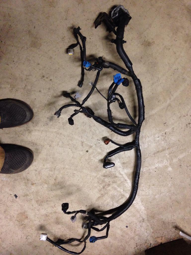 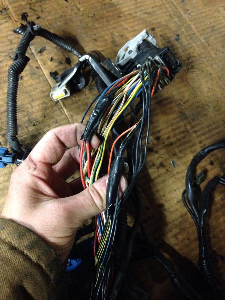 My cheap NASCAR expansion tank arrived. Buying a used tank was cheaper than buying the nice almost-but-not-quite hemispherical tube caps, so I went for it. It'll go nicely with the NASCAR bar. (IMG:style_emoticons/default/laugh.gif) I'm pretty stoked to weld on some mounts, loose the lower wiggins fitting, and go to town with it. 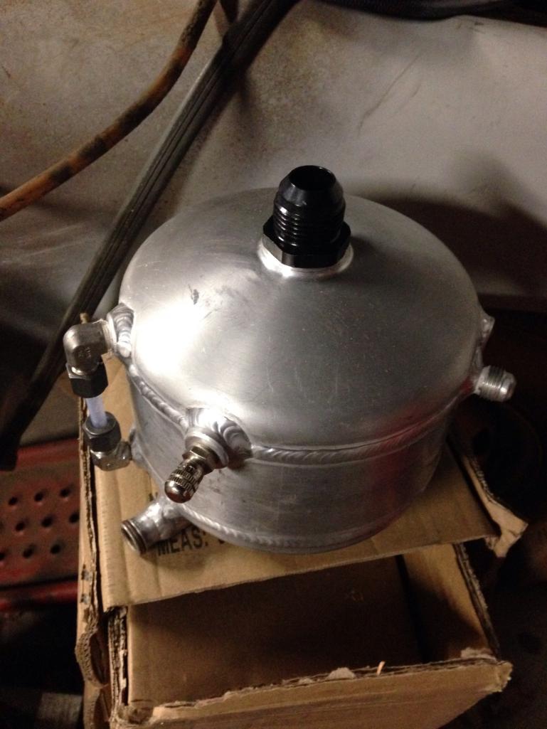 |
|
|
|
| 914forme |
Dec 20 2016, 12:24 PM
Post
#45
|
|
Times a wastin', get wrenchin'! Group: Members Posts: 3,899 Joined: 24-July 04 From: Dayton, Ohio Member No.: 2,388 Region Association: None |
QUOTE(jd74914 @ Dec 20 2016, 11:46 AM) I got a sweet set of single adjustable JRZ shocks for the rear from Stephen (914forme). (IMG:style_emoticons/default/smile.gif) This morning I turned down some 6061 spring spacers so I can run a zero-weight helper spring and avoid having the main spring come off the perches when the car gets jacked up. The smaller lip is for the helper spring and larger for the main coil. These are going into the pile for anodizing now. Nice job on the spacers. |
|
|
|
| jd74914 |
Dec 22 2016, 04:59 PM
Post
#46
|
|
Its alive Group: Members Posts: 4,878 Joined: 16-February 04 From: CT Member No.: 1,659 Region Association: North East States |
QUOTE(914forme @ Dec 20 2016, 01:24 PM) Nice job on the spacers. Thanks! Spending lunch turning spacers to save $50 for other stuff seemed worth it. (IMG:style_emoticons/default/smile.gif) |
|
|
|
| jd74914 |
Dec 22 2016, 05:22 PM
Post
#47
|
|
Its alive Group: Members Posts: 4,878 Joined: 16-February 04 From: CT Member No.: 1,659 Region Association: North East States |
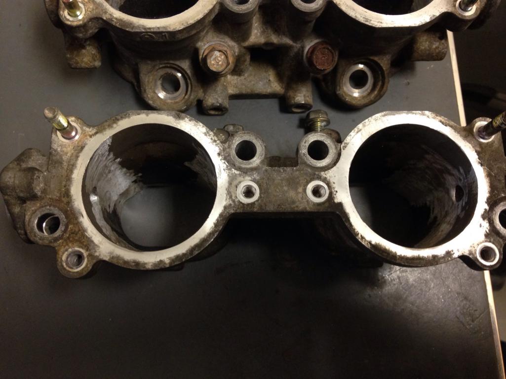
Next up are some TGV deletes. I really just started going through these so I could reduce the I/O on my ECU, not so much for any huge power gains. A bunch of companies sell nice milled versions for not too much money considering the machining complexity (IAG ~$300), but I'm way to cheap to buy them so I decided to do them myself. A lot of people just remove the butterfly valves like in the first pictures below, but given the difficultly to remove it seemed worth it to tally delete the crossbars and smooth the lip the butterfly sits on when closed.
Note: theoretically, the engine probably won't run as well at low revs (especially while cold) with these deleted. When closed they basically reduce the size of the runner dramatically to increase the velocity of flow hitting the injection stream. The increase in velocity would result in increased droplet entrainment, or better mixing. The fuel jet is essentially a jet in crossflow so increasing crossflow (runner) velocity decreases the momentum ratio of the injector stream and should cause it to bend over and not hit the back wall as hard. To delete you basically just: 1) Remove the TGV assemblies-easiest if you first remove the fuel rail 2) Remove the butterflies. Easiest way is to drill out the peened back side of the screws and then use an impact screwdriver on the front. Otherwise you can also just drill out the screws all together. 3) Remove all of the hardware (actuator, position sensor, etc.) 4) Tap out the shaft 5) Use a hacksaw to cut the "cross brace" as close to the inside surface as possible 6) Pick up your favorite die grinder and flame burr and go to town on the remaining brace. While you're at it you might as well smooth the butterfly plate lip. It's easiest if you mount in a vice and then use some beeswax, cutting oil, or machine coolant on your burr so it doesn't gum up. 7) Weld up the shaft holes. 8) Grind welds down smooth and go over whole interior with sanding wheel. 9) Clean up whole TGV body and reinstall (or whatever) I'm only up to step 6 so far-didn't have time to borrow the TIG during lunch today. Hopefully I'll get there next week. (IMG:style_emoticons/default/smile.gif) Disassembled on the bench (4): 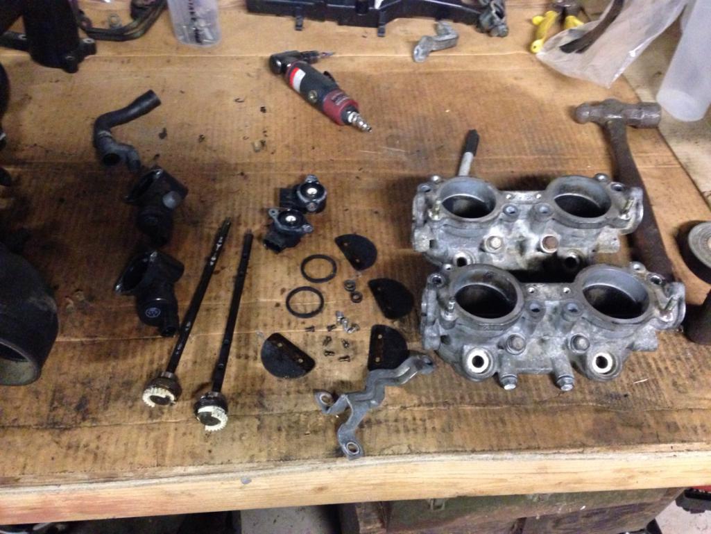 Shot of the cross brace inside before cutting and comparison after cutting (5). 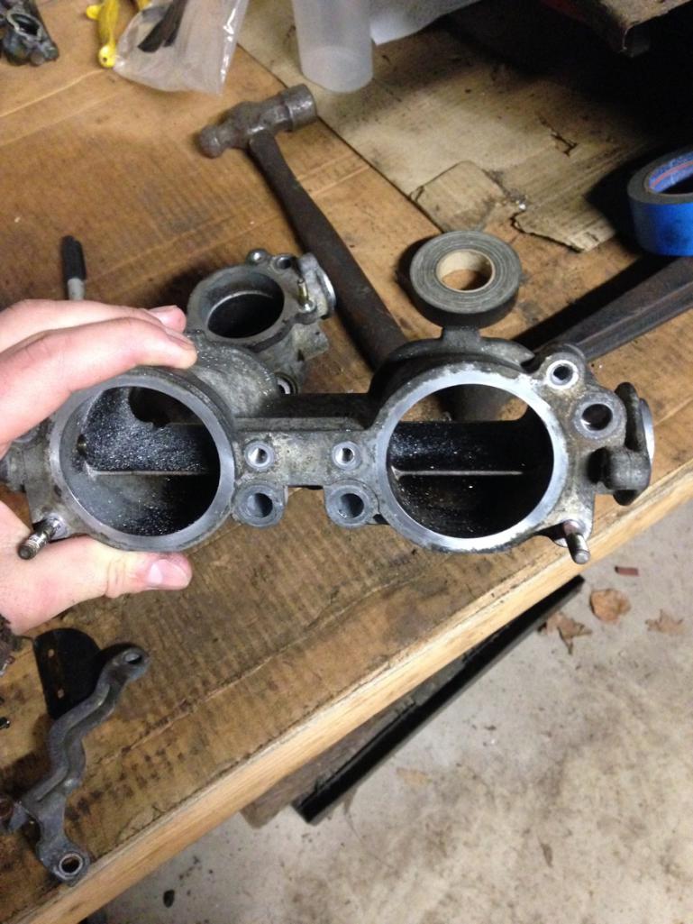 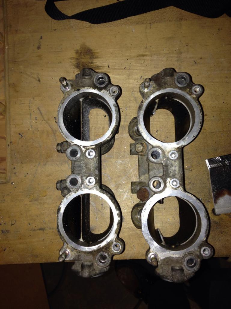 You can see the little lip mentioned in (6) on the opposite side of the TGV interior as the cross brace. 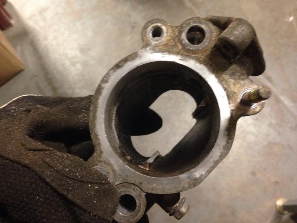 Mounted in the vice after some grinding (6). 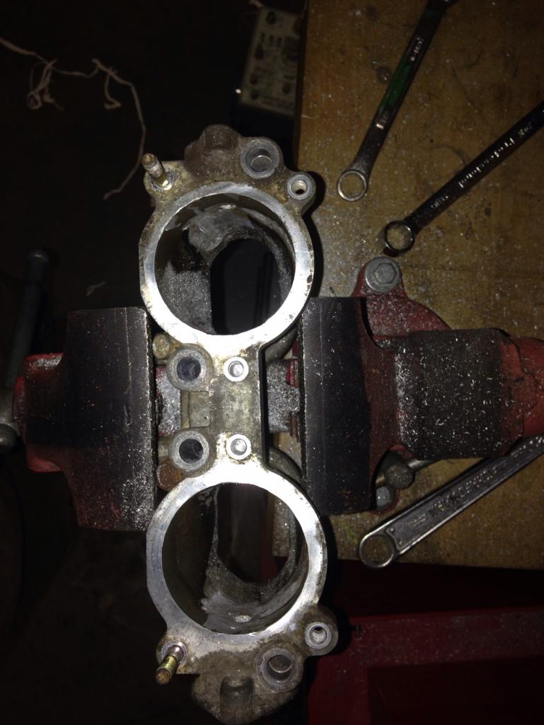 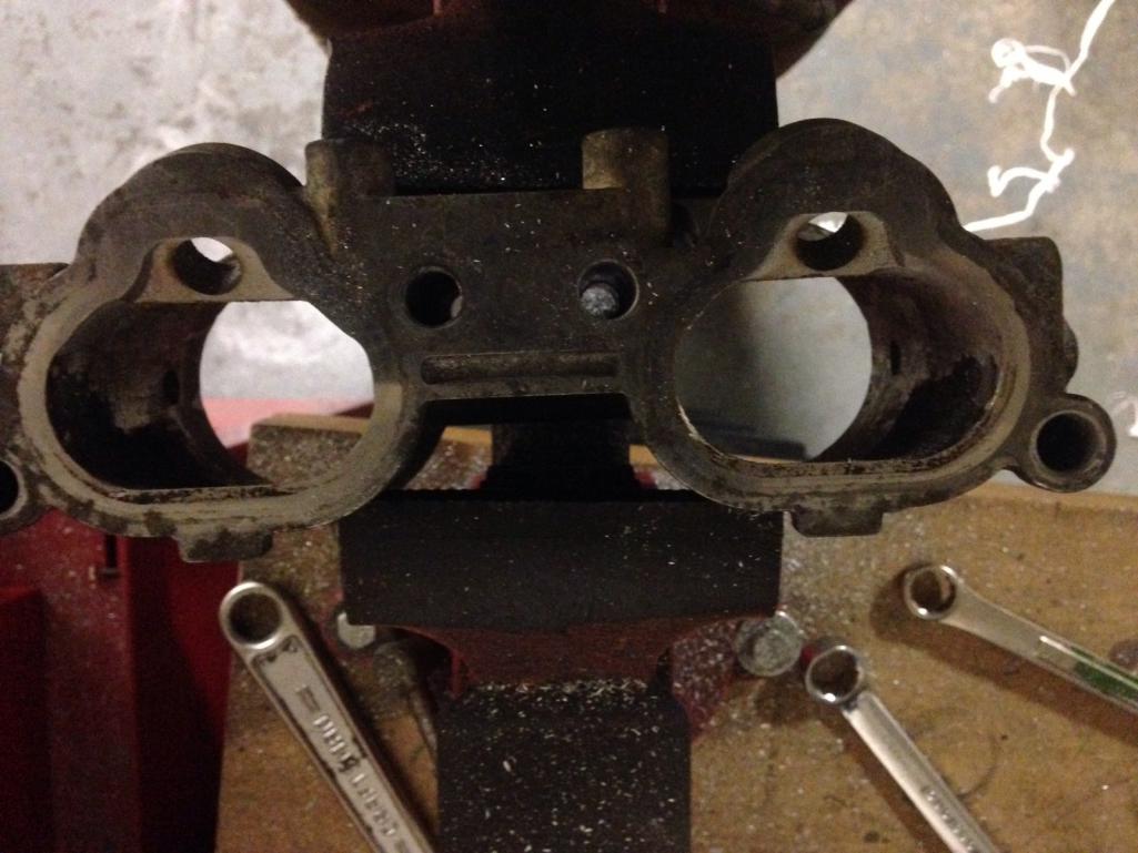 |
|
|
|
| jd74914 |
Dec 22 2016, 05:26 PM
Post
#48
|
|
Its alive Group: Members Posts: 4,878 Joined: 16-February 04 From: CT Member No.: 1,659 Region Association: North East States |
Another view of the material taken out with slightly better lighting.
  The last step is to weld up the shaft holes and do a bit of sanding to remove any small gouges left from the die grinder. The shafts do ride on plastic bushing which are pretty easy to grind out with the grinder (I couldn't get them out by hand, not sure if that's typical or not). I'm probably going to blast these too to try and get rid of some of the oxidation and then paint or something to keep them nice. 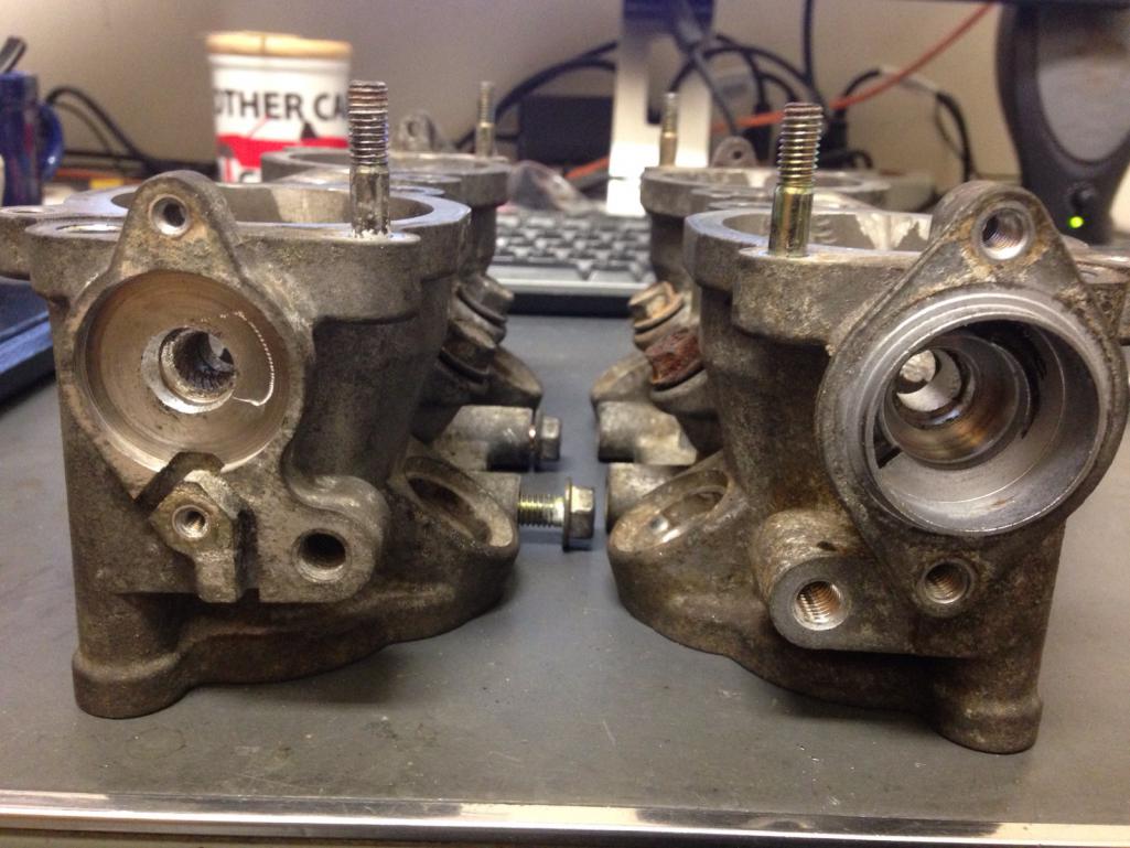 |
|
|
|
| jd74914 |
Dec 29 2016, 11:53 AM
Post
#49
|
|
Its alive Group: Members Posts: 4,878 Joined: 16-February 04 From: CT Member No.: 1,659 Region Association: North East States |
QUOTE(914forme @ Nov 13 2016, 07:21 PM) really love what your doing but over complicating it a bit. The distance front the bar center to the center above the A-Arm is your ideal location since th pivots move in multiple plains. Then you are "stuck" with the number of degrees the amounts will allow your bars to travel with out binding over the range of the suspension. two points in a cad drawing will not tell you that, real world will. This of course is based on the factory U tab on the arms, and a double sheer tab up top running a set of rod ends for the drop links. If you are using a spherical bearing on the arm, or a different high angle mount, then your movement can be greater. Looking forward to seeing your solution to the Nascar bar mounts. I know I gave lots of thought to mine before I said (IMG:style_emoticons/default/WTF.gif) and just did it! Best solution (IMG:style_emoticons/default/confused24.gif) I do know they do not bind with bar rotation. I'm planning on running a high misalignment rod end on the arm-side to gain a bit more travel. That said, as angle increases the force applied to the arm increases tremendously, so buckling can become a concern. I still haven't gotten a change to measure everything yet so we'll see. (IMG:style_emoticons/default/smile.gif) The mounts will look similar to OEM mounts. I wanted to keep the mounting geometry the same so I'd be easy to align and let me use the stiffening plates from MADDOG. The big difference is that instead of the OEM bushing, I'm going to use a Frelon-lined flanged sleeve bearing. These are self-lubricating and are supposed to last well in dirty environments but that's something driving will need to validate. The bar certainly spins well in them! (IMG:style_emoticons/default/laugh.gif) The CAD views are below (drew it up to check some clearances before making chips and buying fasteners). I'm going to machine first thing next week when my metal comes in (6061-T6). They are a bit beefy, but I really didn't want to risk HCF cracking after a few years of use and exposure to sand/salt. The gap you see between the bushing mount and backing plate is ~0.110 to account for inner fender and stiffener thickness. 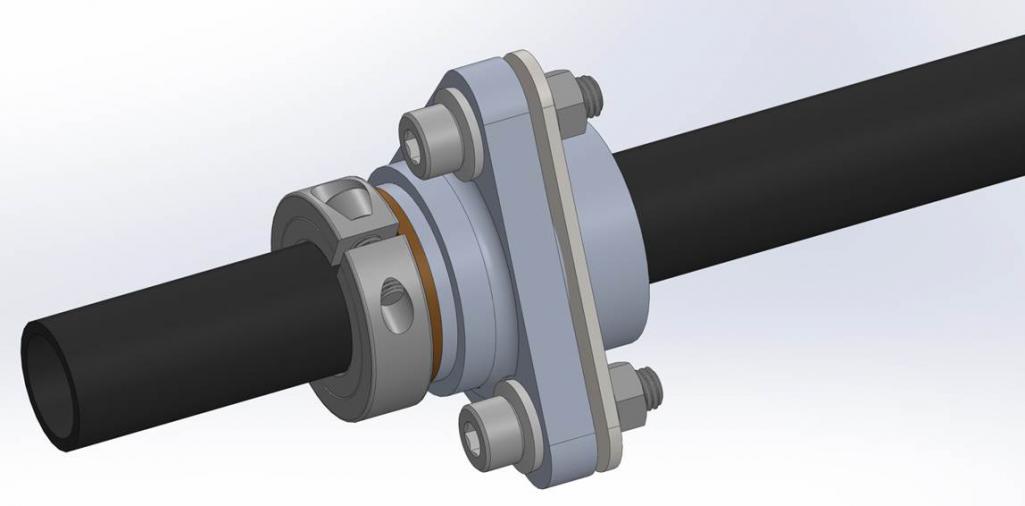 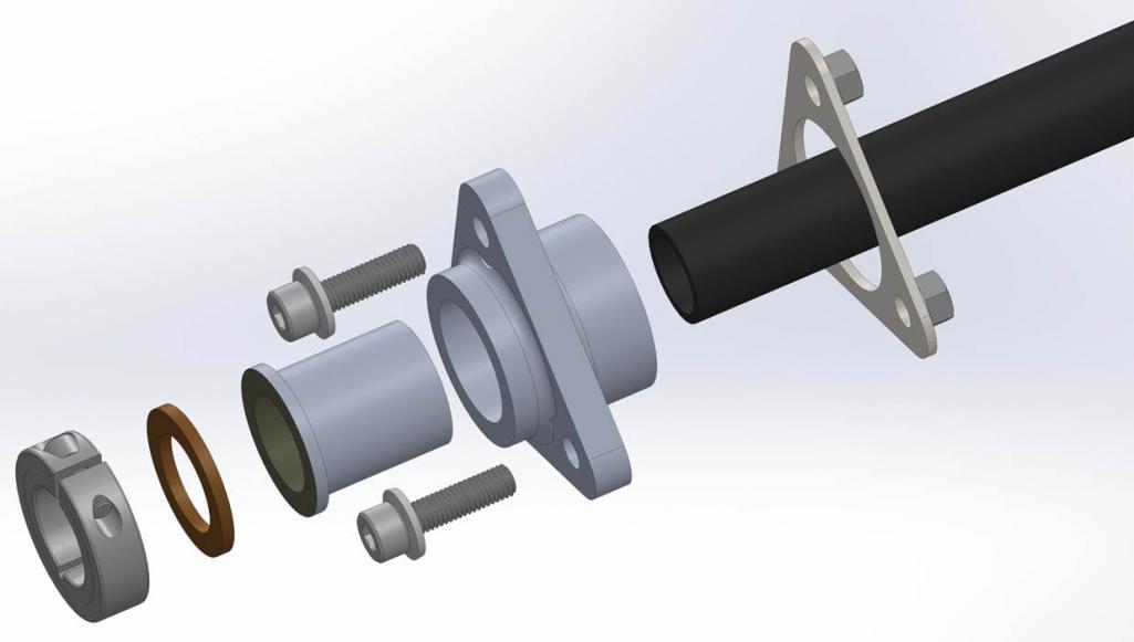 |
|
|
|
| 914forme |
Dec 29 2016, 12:32 PM
Post
#50
|
|
Times a wastin', get wrenchin'! Group: Members Posts: 3,899 Joined: 24-July 04 From: Dayton, Ohio Member No.: 2,388 Region Association: None |
Nice design
|
|
|
|
| jd74914 |
Dec 29 2016, 04:18 PM
Post
#51
|
|
Its alive Group: Members Posts: 4,878 Joined: 16-February 04 From: CT Member No.: 1,659 Region Association: North East States |
QUOTE(914forme @ Dec 29 2016, 01:32 PM) Nice design Thanks! Hopefully it works ok... The bushing is nearly centered on inner fender to try and minimize any cantilever action (like the stock setup) from slight misalignment across the car. Not sure if it'll do anything, especially given the addition of the inner fender doubler, but it seemed like it couldn't hurt. |
|
|
|
| 914_teener |
Dec 29 2016, 04:34 PM
Post
#52
|
|
914 Guru Group: Members Posts: 5,270 Joined: 31-August 08 From: So. Cal Member No.: 9,489 Region Association: Southern California |
Interesting...gosh I wish I had the toys and tools at my work....and the time.
I put the split ring retainer on the inside of the fenderwell....quess I could have put it on the outside....don.t see why that wouldn.t work. |
|
|
|
| jd74914 |
Dec 29 2016, 05:44 PM
Post
#53
|
|
Its alive Group: Members Posts: 4,878 Joined: 16-February 04 From: CT Member No.: 1,659 Region Association: North East States |
QUOTE(914_teener @ Dec 29 2016, 05:34 PM) Interesting...gosh I wish I had the toys and tools at my work....and the time. I put the split ring retainer on the inside of the fenderwell....quess I could have put it on the outside....don.t see why that wouldn.t work. Yeah, I'm pretty lucky. (IMG:style_emoticons/default/smile.gif) By virtue of being in grad school, I effectively have all 60++ hr work weeks, but I've been trying to use small downtime to make stuff lately to get this thing done. The really nice thing is that in addition to having access to a lot of machinery we have two really skilled machinists who enjoy teaching. I'm only putting the collar on the outside so the bar and bushings can be pulled without tank removal. Inside would certainly make for a cleaner install. (IMG:style_emoticons/default/idea.gif) |
|
|
|
| 914forme |
Dec 29 2016, 06:33 PM
Post
#54
|
|
Times a wastin', get wrenchin'! Group: Members Posts: 3,899 Joined: 24-July 04 From: Dayton, Ohio Member No.: 2,388 Region Association: None |
Collar on the outside it is a functional piece not aesthetics.
BTW, Mine using a standard spherical bearing and mounts found on ag equipment. They are dirt cheap and handle misalignments very well. 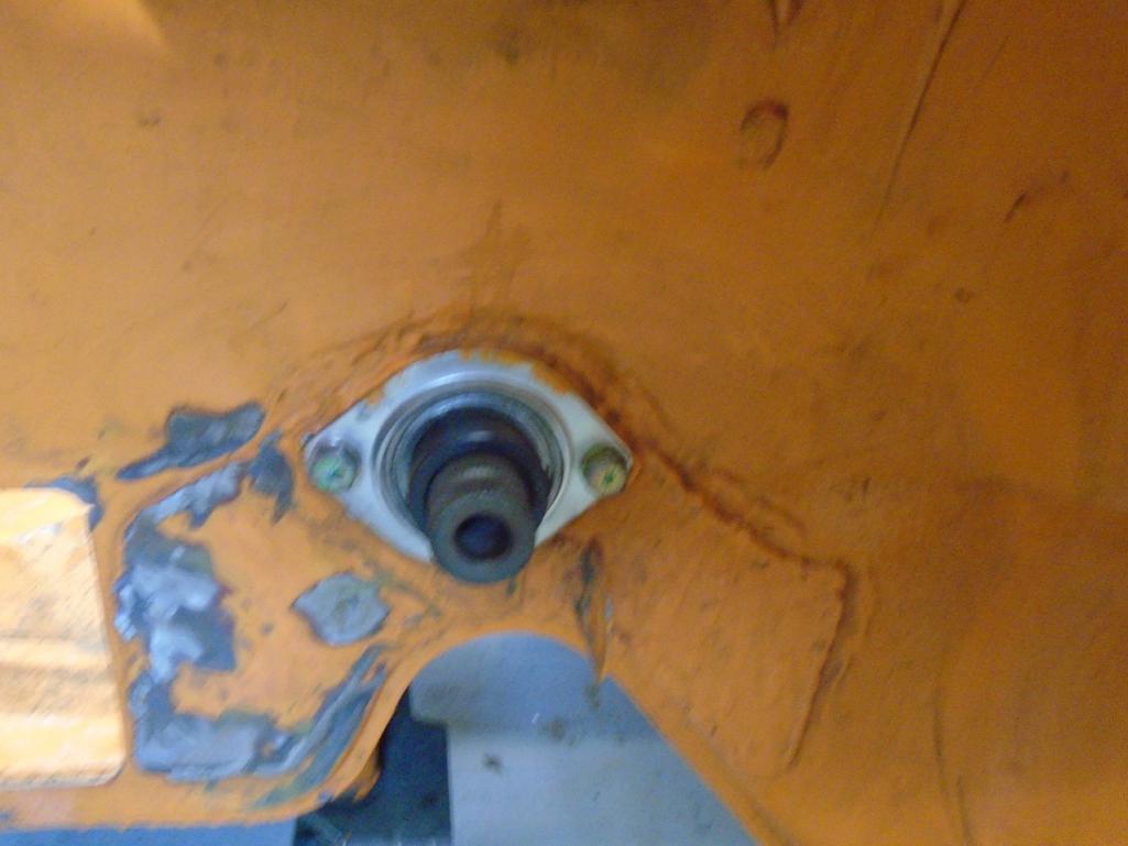 Collars lock them in place on the outside. I changed the arms to be double shear this year, will see how it works. 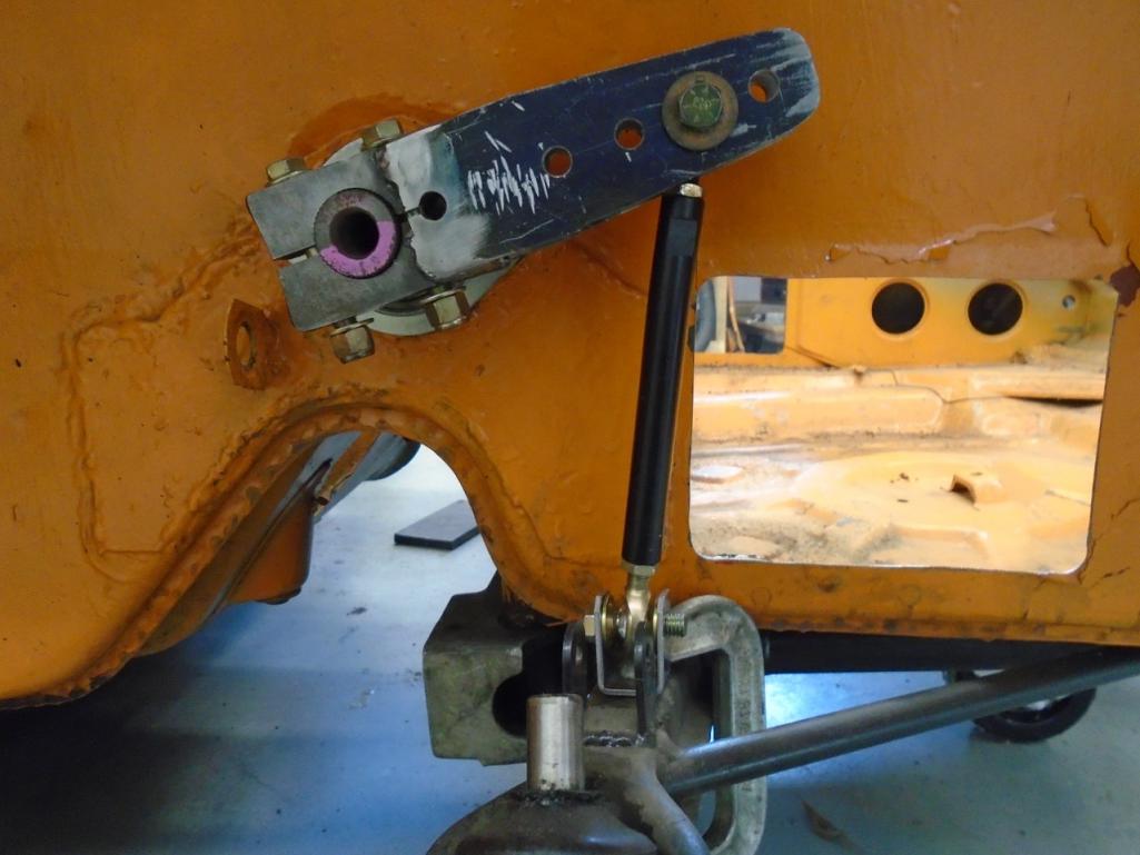 Great idea, soaking up all the machining knowledge you can. Always good to know how stuff is built. |
|
|
|
| jd74914 |
Dec 29 2016, 07:19 PM
Post
#55
|
|
Its alive Group: Members Posts: 4,878 Joined: 16-February 04 From: CT Member No.: 1,659 Region Association: North East States |
QUOTE(914forme @ Dec 29 2016, 07:33 PM) BTW, Mine using a standard spherical bearing and mounts found on ag equipment. They are dirt cheap and handle misalignments very well. I changed the arms to be double shear this year, will see how it works. Thanks for the pictures! Yeah, those flanged sphericals are pretty nice. If these don't work well I'll go that route. It's easy enough to swap. The double shear arms are much better than single shear. I have a set of aluminum arms from Speedway (like 18 inches long now (IMG:style_emoticons/default/laugh.gif) ) that will be cut down. I'm trying to figure out how to put them in double shear. It seems preferable even if it requires an additional piece and fastener. Are you using 5/16" or 3/8" rod ends? QUOTE(914forme @ Dec 29 2016, 07:33 PM) Great idea, soaking up all the machining knowledge you can. Always good to know how stuff is built. Yep-just shooting for a more holistic education, especially since it's likely that I'll never have access to the same resources in any future jobs. The unfortunate part is that after graduation the garage is definately going to at least need a knee mill with TRAK controller and lathe. (IMG:style_emoticons/default/laugh.gif) |
|
|
|
| 914forme |
Dec 30 2016, 07:44 AM
Post
#56
|
|
Times a wastin', get wrenchin'! Group: Members Posts: 3,899 Joined: 24-July 04 From: Dayton, Ohio Member No.: 2,388 Region Association: None |
Jim
3/8" due to me having a huge number of 3/8" hardware on hand. The speedway stuff is super nice, you can make it double sheer by cutting it down to the area needed for bar engagement and then welding on so sides. Since it is AL, you will need thicker pieces than mine. Which where over kill at 3/16" I could have done it with 1/8" but the bar I am using is huge compared to the one I modeled it after. I understand the holistic education keep it up. As for the need for machine tools in the garage, I waited 30 years before I got a Metal Lathe and Mill. They are small units, yet now I think why did I never have the Lathe before. IT is the most used item in the shop even surpassed the welders. (IMG:style_emoticons/default/confused24.gif) Mill gets used about 1/16th as much. I now need a bigger Lathe, and well I would love to have an larger mill but they take up a lot of space, for the little usage it would get. |
|
|
|
| jd74914 |
Jan 4 2017, 04:38 PM
Post
#57
|
|
Its alive Group: Members Posts: 4,878 Joined: 16-February 04 From: CT Member No.: 1,659 Region Association: North East States |
QUOTE(914forme @ Dec 30 2016, 08:44 AM) 3/8" due to me having a huge number of 3/8" hardware on hand. The speedway stuff is super nice, you can make it double sheer by cutting it down to the area needed for bar engagement and then welding on so sides. Since it is AL, you will need thicker pieces than mine. Which where over kill at 3/16" I could have done it with 1/8" but the bar I am using is huge compared to the one I modeled it after. Ok, gotcha. From a load standpoint 5/16" seems ok so I'm thinking about going that way since I have a ton of 5/16" stuff from another project. Yeah, I'm not sure about welding yet. I'm comfortable welding steel ends, but the post-weld non-heat treated aluminum scares me a little bit. Got another idea but need to do some more thinking. QUOTE(914forme @ Dec 30 2016, 08:44 AM) I waited 30 years before I got a Metal Lathe and Mill. They are small units, yet now I think why did I never have the Lathe before. IT is the most used item in the shop even surpassed the welders. (IMG:style_emoticons/default/confused24.gif) Mill gets used about 1/16th as much. Interesting. In car fab like this I guess you do tend to need lots of pieces turned and there isn't really any other machine that can do it. Lathe first then! (IMG:style_emoticons/default/laugh.gif) (IMG:style_emoticons/default/happy11.gif) |
|
|
|
| jd74914 |
Jan 4 2017, 04:54 PM
Post
#58
|
|
Its alive Group: Members Posts: 4,878 Joined: 16-February 04 From: CT Member No.: 1,659 Region Association: North East States |
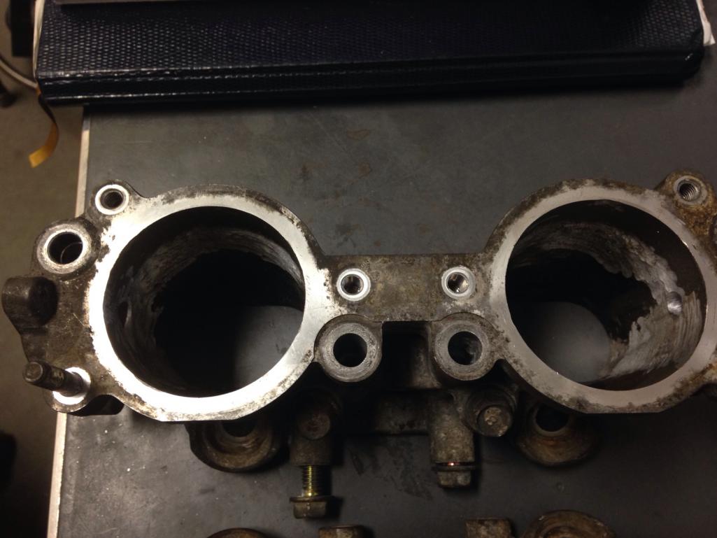
Finished the TGV removal finally! One more part down-perhaps not super necessary but...
Some more pictures just in case anyone needs them for reference in the future. Welded up throttle shaft holes. Some people on NAISOC, etc. JB weld them up or press rods in there and others even leave the centers connected, but welding seems the most robust solution. It would suck to get a piece of something down into the intake valves. I don't have a hot tank or ultrasonic cleaners so I only was able to grind down the surface oxidation and degrease by hand with a wire brush. The casting is pretty porous and has a lot of embedded oil/fuel so it is a little rough to weld. The easiest way to get a decent weld is to 1) pass the TIG torch over the hole's edge to burn off some of the impurities, 2) clean the tungsten, 3) wire brush/acetone the surface again, and then 4) weld. Having a fume hood is nice too given the amount of smoking. 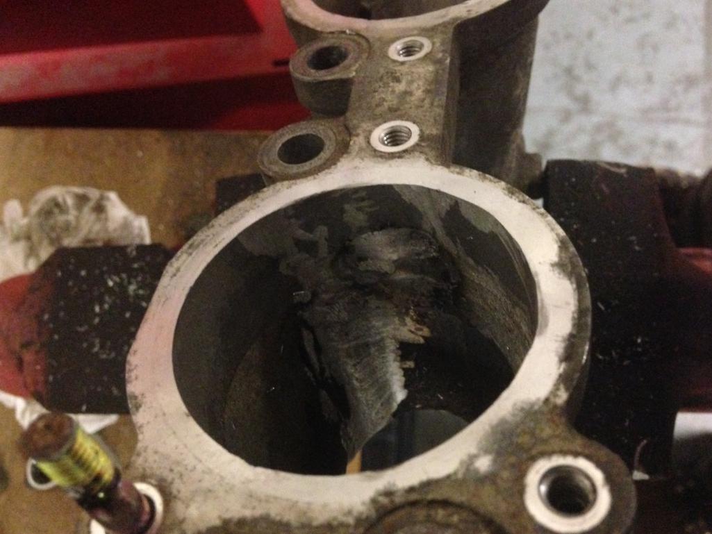 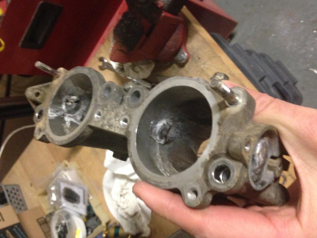 Cut down as much of the proud welds as possible with a carbide burr (saves flap wheels). 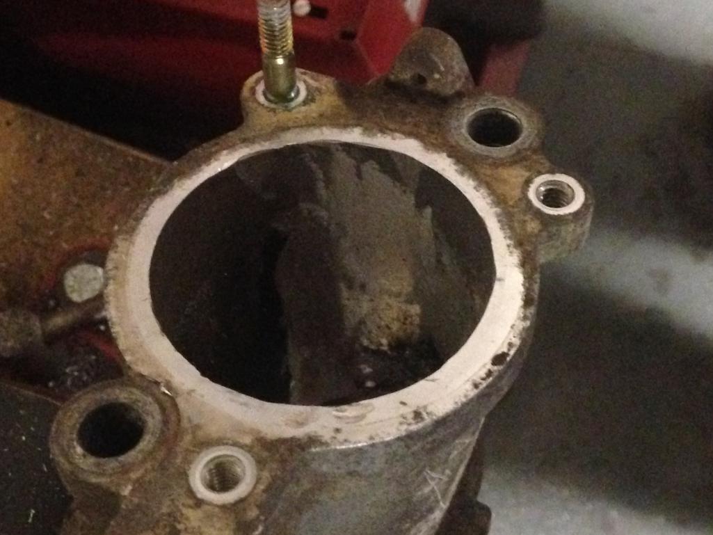 |
|
|
|
| jd74914 |
Jan 4 2017, 04:56 PM
Post
#59
|
|
Its alive Group: Members Posts: 4,878 Joined: 16-February 04 From: CT Member No.: 1,659 Region Association: North East States |
The final product after hitting it with a 60-grit flap wheel. It's a bit tough to judge the surface from the poorly lit pictures, but it's pretty smooth. I'm reasonably happy with how they turned out for a few hours of work. (IMG:style_emoticons/default/smile.gif)
Thinking of blasting these and sending out for powder coating with a batch of stuff later on. 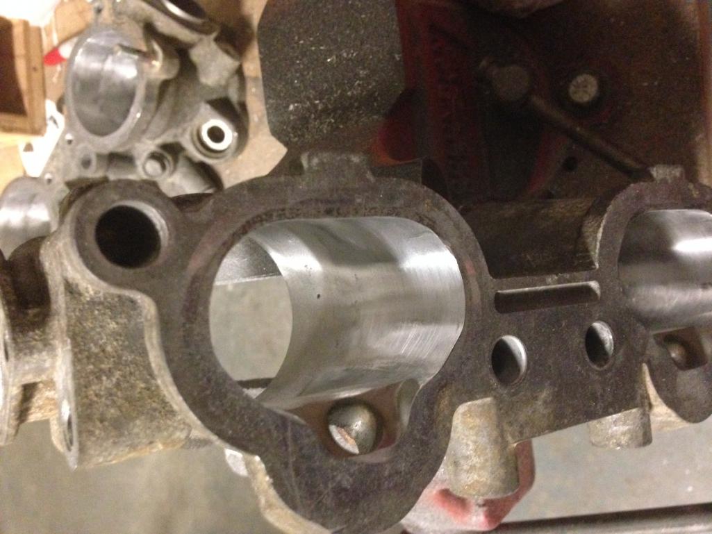 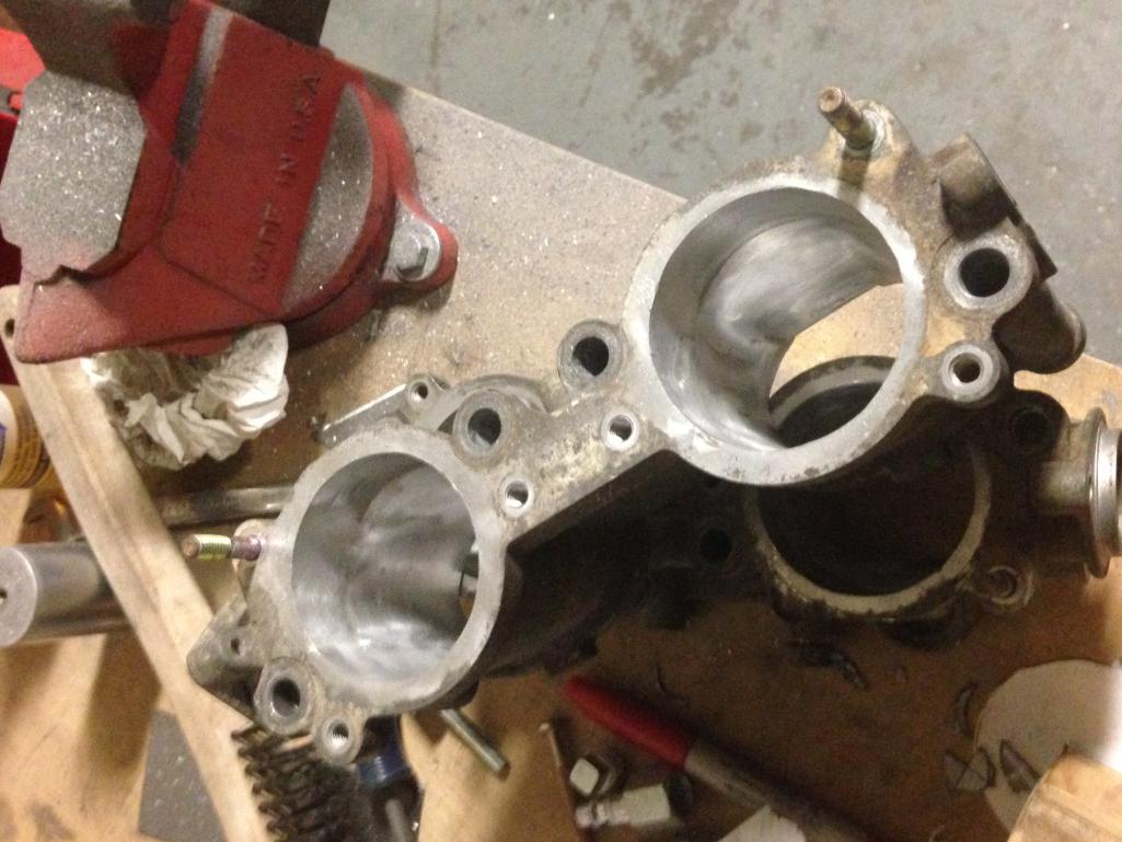 |
|
|
|
| jd74914 |
Jan 4 2017, 04:58 PM
Post
#60
|
|
Its alive Group: Members Posts: 4,878 Joined: 16-February 04 From: CT Member No.: 1,659 Region Association: North East States |
Also unpacked the left rear inner fender wheel Chris (Tygaboy) cut out for me. This should be perfect for filling the huge hole in my left side!
I should have taken a picture of the packing...this sounds dumb but it was the best packed piece of sheet metal I've ever gotten. I wouldn't hesitate to buy from Chris again! 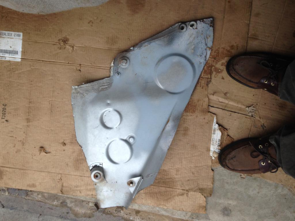 |
|
|
|
|
1 User(s) are reading this topic (1 Guests and 0 Anonymous Users)
0 Members:

|
Lo-Fi Version | Time is now: 26th May 2026 - 09:44 PM |
Invision Power Board
v9.1.4 © 2026 IPS, Inc.