|
|
|
Porsche, and the Porsche crest are registered trademarks of Dr. Ing. h.c. F. Porsche AG.
This site is not affiliated with Porsche in any way. Its only purpose is to provide an online forum for car enthusiasts. All other trademarks are property of their respective owners. |
|
|

  |

| Spoke |
 Jan 17 2015, 12:17 AM Jan 17 2015, 12:17 AM
Post
#201
|
|
Jerry  Group: Members Posts: 6,973 Joined: 29-October 04 From: Allentown, PA Member No.: 3,031 Region Association: None |
I think this is the crimp part to use. Your local FLAPS should also have it.
Crimp at Radio Shack Determine the 31 wire (ground; should be brown) and the K wire and crimp them together. Attached image(s) 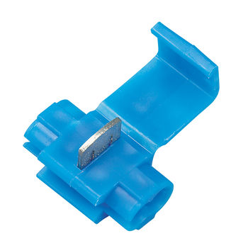
|
   |

 
|
| cary |
Jan 17 2015, 01:01 AM
Post
#202
|
|
Advanced Member Group: Members Posts: 3,900 Joined: 26-January 04 From: Sherwood Oregon Member No.: 1,608 Region Association: Pacific Northwest |
Ok that makes me feel better. I was beginning to feel like a dumb ass.
On the 73 schematic the ground is brown and the common is BLUE/white. |
 |
|
| Spoke |
Jan 17 2015, 10:13 AM
Post
#203
|
|
Jerry Group: Members Posts: 6,973 Joined: 29-October 04 From: Allentown, PA Member No.: 3,031 Region Association: None |
QUOTE(cary @ Jan 17 2015, 02:01 AM)  Ok that makes me feel better. I was beginning to feel like a dumb ass. On the 73 schematic the ground is brown and the common is black/white. That was my fault. I had never seen or replaced the flasher and thought the piggyback spade would work but not with the single connector for all 4 wires. Thanks for the pics. I will include one of the crimp connectors with front or rear LED turnsignal boards. Cheers (IMG:style_emoticons/default/beerchug.gif) |
|
|
|
| Spoke |
Jan 17 2015, 10:21 AM
Post
#204
|
|
Jerry Group: Members Posts: 6,973 Joined: 29-October 04 From: Allentown, PA Member No.: 3,031 Region Association: None |
QUOTE(Spoke @ Jan 17 2015, 01:17 AM) I think this is the crimp part to use. Your local FLAPS should also have it. Crimp at Radio Shack Determine the 31 wire (ground; should be brown) and the K wire and crimp them together. Upon further review, I'm not sure this crimp connector will work because it takes one existing wire and may require the second wire to be cut and inserted into the other slot. I'd like to see a solution where neither wire is cut. This article shows better pics of some of the wire-tap connectors on the market. Bare Ass Chopper Article |
|
|
|
| Spoke |
Jan 17 2015, 10:27 AM
Post
#205
|
|
Jerry Group: Members Posts: 6,973 Joined: 29-October 04 From: Allentown, PA Member No.: 3,031 Region Association: None |
mikesmith solved this dash indicator issue by making a pigtail to ground both the dash indicators to the existing ground lug on the tach.
Attached thumbnail(s) 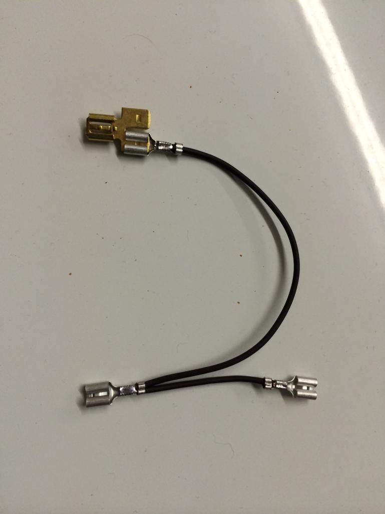 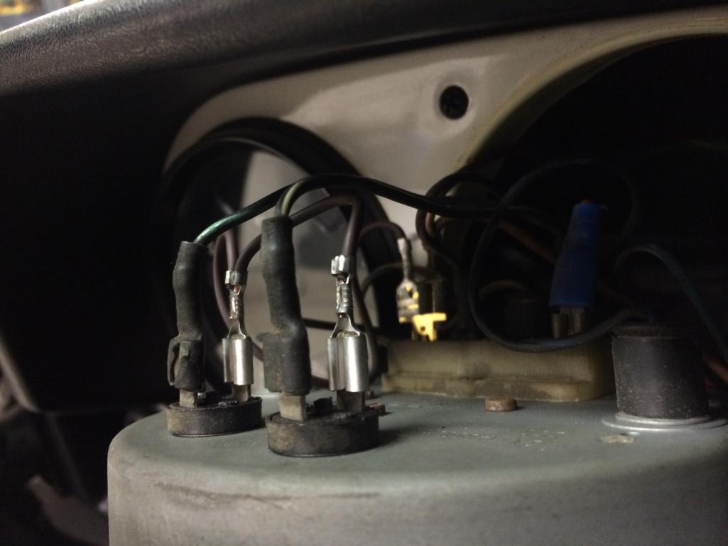 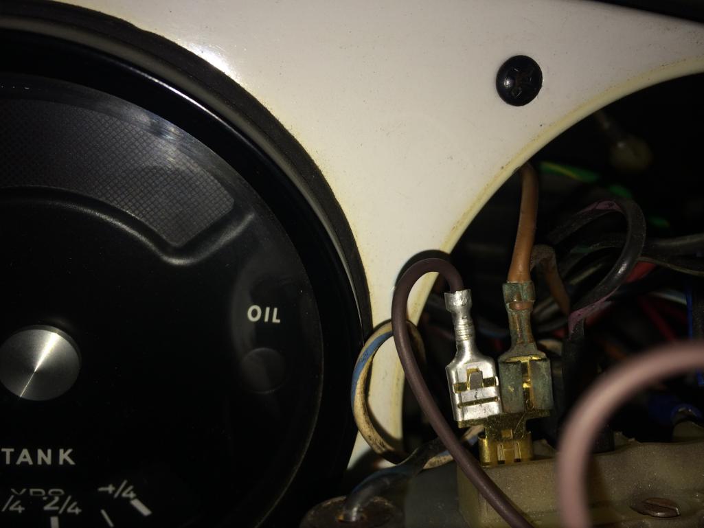
|
|
|
|
| euro911 |
Jan 17 2015, 12:39 PM
Post
#206
|
|
Retired & living the dream. God help me if I wake up! Group: Members Posts: 8,845 Joined: 2-December 06 From: So.Cal. & No.AZ (USA) Member No.: 7,300 Region Association: Southern California |
QUOTE(Spoke @ Jan 17 2015, 08:21 AM) ... You can cut the plastic 'block' at the end of the connector body to allow the second wire to pass through it.Upon further review, I'm not sure this crimp connector will work because it takes one existing wire and may require the second wire to be cut and inserted into the other slot. I'd like to see a solution where neither wire is cut. This article shows better pics of some of the wire-tap connectors on the market. Bare Ass Chopper Article |
|
|
|
| cary |
Jan 17 2015, 01:30 PM
Post
#207
|
|
Advanced Member Group: Members Posts: 3,900 Joined: 26-January 04 From: Sherwood Oregon Member No.: 1,608 Region Association: Pacific Northwest |
Does the indicator common just need to go ground.
Or does it need some sort of top secret ground signal from the flasher ground. |
|
|
|
| Spoke |
Jan 17 2015, 01:45 PM
Post
#208
|
|
Jerry Group: Members Posts: 6,973 Joined: 29-October 04 From: Allentown, PA Member No.: 3,031 Region Association: None |
QUOTE(cary @ Jan 17 2015, 02:30 PM) Does the indicator common just need to go ground. Or does it need some sort of top secret ground signal from the flasher ground. The dash indicator common just goes to ground; any ground. It behaves then like any of the front or rear turnsignal lamps. |
|
|
|
| cary |
Jan 23 2015, 12:20 AM
Post
#209
|
|
Advanced Member Group: Members Posts: 3,900 Joined: 26-January 04 From: Sherwood Oregon Member No.: 1,608 Region Association: Pacific Northwest |
Pulled the tach out.
Looks like I mis-read the wiring diagram. The common is blue/white. So looking at mikesmith's work. I'll remove the blue/white wires and zip tie them out of the way. Then replace them with the 3 wire jumper. 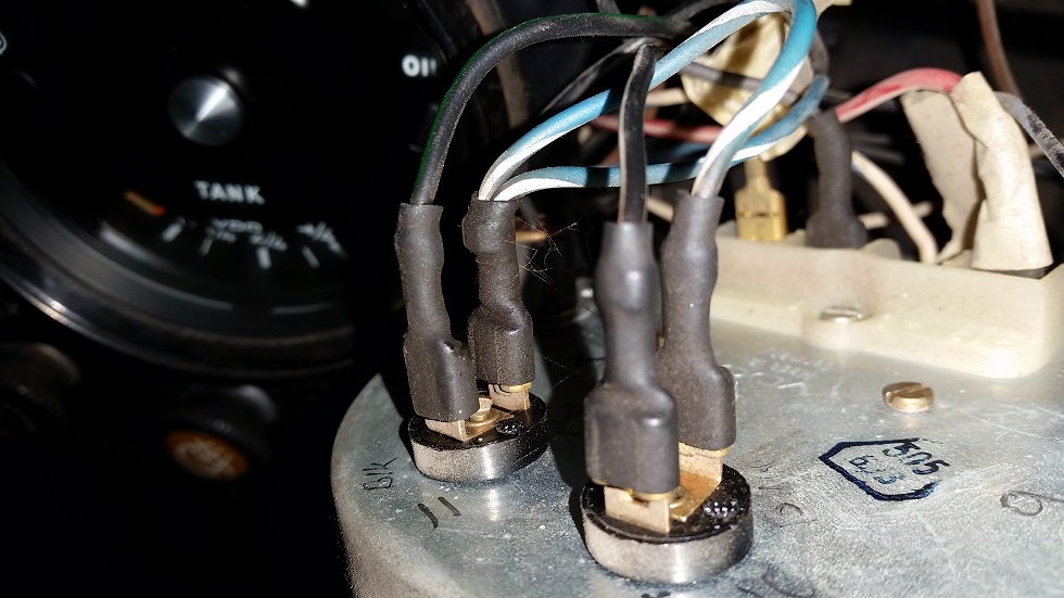 |
|
|
|
| mikesmith |
Jan 23 2015, 02:26 AM
Post
#210
|
|
Member Group: Members Posts: 202 Joined: 5-September 13 From: SF Member No.: 16,354 Region Association: Northern California |
QUOTE(cary @ Jan 22 2015, 10:20 PM) Pulled the tach out. Looks like I mis-read the wiring diagram. The common is blue/white. So looking at mikesmith's work. I'll remove the blue/white wires and zip tie them out of the way. Then replace them with the 3 wire jumper. That's what I did. Make sure you insulate the ends of the blue/white wires so that they can't short to ground. Sorry about the bad lighting in the shot I sent to Spoke. |
|
|
|
| cary |
Jan 23 2015, 07:13 AM
Post
#211
|
|
Advanced Member Group: Members Posts: 3,900 Joined: 26-January 04 From: Sherwood Oregon Member No.: 1,608 Region Association: Pacific Northwest |
I think I'll pull them back to the flasher socket and zip tie them to the harness below it.
That way they're out of the way and obvious as to what they are. Thanks for the engineering. |
|
|
|
| cary |
Jan 24 2015, 09:32 PM
Post
#212
|
|
Advanced Member Group: Members Posts: 3,900 Joined: 26-January 04 From: Sherwood Oregon Member No.: 1,608 Region Association: Pacific Northwest |
Got home early and worked on the indicator grounds.
Works like a champ. Couldn't pull the common back the socket. Harness taped up in a couple different spots. Thanks from all the help. Patiently waiting for the front LED lights. I also installed my new Euro front lenses from Camp914. https://www.youtube.com/watch?v=NlUfLRn8eA0 |
|
|
|
|
1 User(s) are reading this topic (1 Guests and 0 Anonymous Users)
0 Members:

|
Lo-Fi Version | Time is now: 24th April 2024 - 10:21 PM |
Invision Power Board
v9.1.4 © 2024 IPS, Inc.