|
|
|
Porsche, and the Porsche crest are registered trademarks of Dr. Ing. h.c. F. Porsche AG.
This site is not affiliated with Porsche in any way. Its only purpose is to provide an online forum for car enthusiasts. All other trademarks are property of their respective owners. |
|
|

  |

| Jetsetsurfshop |
 May 7 2014, 08:11 AM May 7 2014, 08:11 AM
Post
#1
|
|
Senior Member  Group: Members Posts: 814 Joined: 7-April 11 From: Marco Island Florida Member No.: 12,907 Region Association: South East States |
Can anyone detail this install on the oil filler/vent system here? Looking for any ideas here. Also, what does everyone use for the gasket on the stock chimney?
Attached image(s) 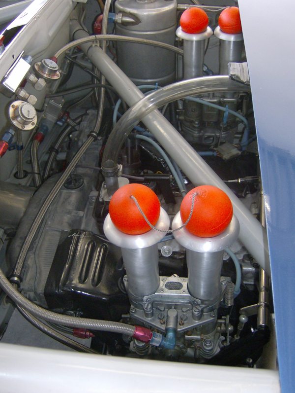
|
   |

 
|
| ChrisFoley |
May 7 2014, 10:42 AM
Post
#2
|
|
I am Tangerine Racing Group: Members Posts: 7,922 Joined: 29-January 03 From: Bolton, CT Member No.: 209 Region Association: None |
I'm not sure what Les has for a tank at the end of that hose.
This is the breather I use with one of my engines. The two side hoses go to the valve covers. 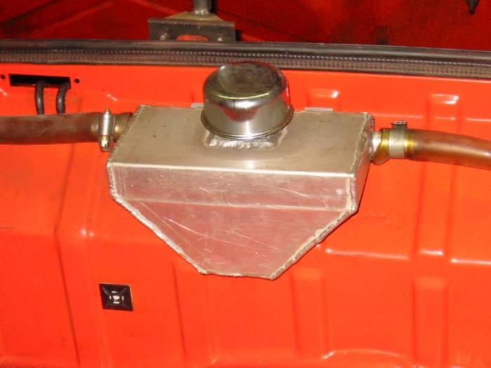 The center hose drains back any oil that gets up to the tank. I have a piece of fuel cell foam inside the tank.  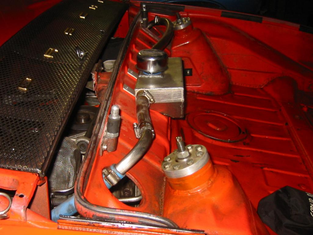 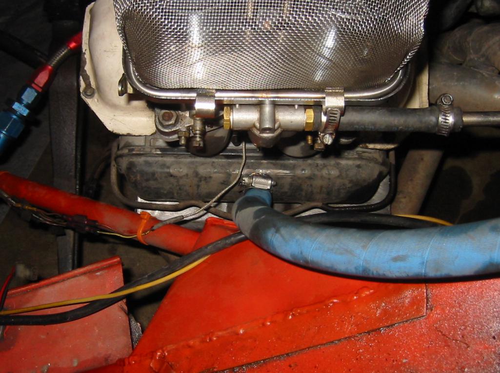 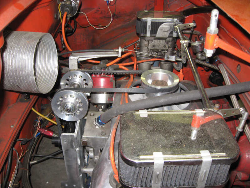 |
 |
|
| ChrisFoley |
May 7 2014, 10:45 AM
Post
#3
|
|
I am Tangerine Racing Group: Members Posts: 7,922 Joined: 29-January 03 From: Bolton, CT Member No.: 209 Region Association: None |
If your heads are unvented this is all you need.
The breather tower is from a 1.8L. The small black hose from the bottom of the can returns any oil. 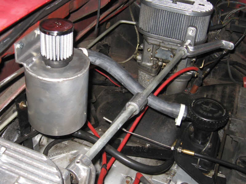 |
|
|
|
| Jetsetsurfshop |
May 7 2014, 08:38 PM
Post
#4
|
|
Senior Member Group: Members Posts: 814 Joined: 7-April 11 From: Marco Island Florida Member No.: 12,907 Region Association: South East States |
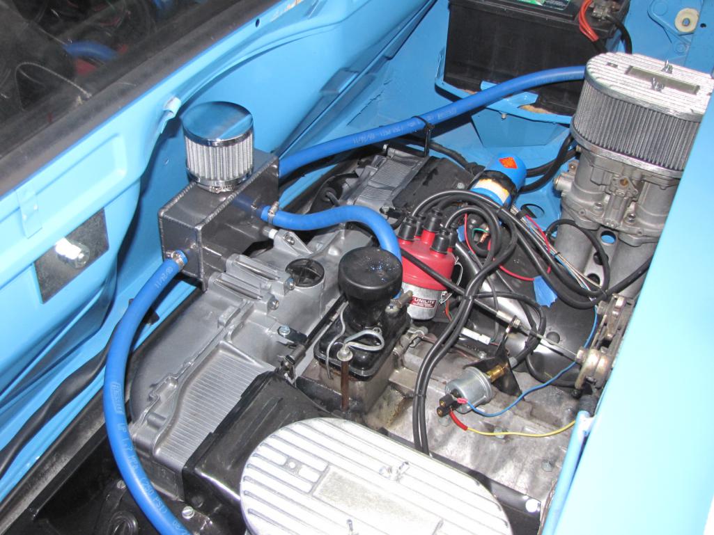
QUOTE(Racer Chris @ May 7 2014, 08:45 AM)  If your heads are unvented this is all you need. The breather tower is from a 1.8L. The small black hose from the bottom of the can returns any oil. Heres what I have now. What do you use on the cork gasket on the chimney? Has anyone modified the oil cap? Attached thumbnail(s) 
|
|
|
|
| ChrisFoley |
May 8 2014, 04:35 AM
Post
#5
|
|
I am Tangerine Racing Group: Members Posts: 7,922 Joined: 29-January 03 From: Bolton, CT Member No.: 209 Region Association: None |
I just use the cork gasket with no sealant.
914Rubber sells a thicker gasket if you don't have enough pressure on the standard ones. I've rebent the bale to tighten it up on some cars. The vapors need an unrestricted path. I think you can use the cap from a d-jet filler tower, or just modify the l-jet cap. |
|
|
|
| Jetsetsurfshop |
May 8 2014, 05:31 AM
Post
#6
|
|
Senior Member Group: Members Posts: 814 Joined: 7-April 11 From: Marco Island Florida Member No.: 12,907 Region Association: South East States |
QUOTE(Racer Chris @ May 8 2014, 02:35 AM) I just use the cork gasket with no sealant. 914Rubber sells a thicker gasket if you don't have enough pressure on the standard ones. I've rebent the bale to tighten it up on some cars. The vapors need an unrestricted path. I think you can use the cap from a d-jet filler tower, or just modify the l-jet cap. We that gives me a lot to do tonight. (IMG:style_emoticons/default/laugh.gif) Did you remove the lower half of you oil cap. (no idea if its a D or I jet engine) We talked about removing it completely. Re bending the bale has been on my mind too. Thanks for the help Chris. |
|
|
|
| ChrisFoley |
May 8 2014, 07:52 AM
Post
#7
|
|
I am Tangerine Racing Group: Members Posts: 7,922 Joined: 29-January 03 From: Bolton, CT Member No.: 209 Region Association: None |
QUOTE(Jetsetsurfshop @ May 8 2014, 06:31 AM) Did you remove the lower half of you oil cap. I just checked into this. The D-jet cap is smaller in diameter, so it won't work. You have to mod the cap made for that (L-jet) tower. Remove the spring (acts as a filter only) and cut off the lower flange. |
|
|
|
| ww914 |
May 8 2014, 08:28 AM
Post
#8
|
|
914 Convert Group: Members Posts: 435 Joined: 29-September 11 From: Central Coast, CA Member No.: 13,621 Region Association: Central California |
This is the setup I use and it works quite well. The two side lines go to the 2.0 heads which have a vent. No need to cut into the valve covers, but that would work too. I designed the box and cut the pieces, but had a real welder weld it up. The middle hose goes back to the already there elbow in the oil filler cap. Not sure what other engines had.
 |
|
|
|
| Jetsetsurfshop |
May 8 2014, 10:27 AM
Post
#9
|
|
Senior Member Group: Members Posts: 814 Joined: 7-April 11 From: Marco Island Florida Member No.: 12,907 Region Association: South East States |
QUOTE(ww914 @ May 8 2014, 06:28 AM) This is the setup I use and it works quite well. The two side lines go to the 2.0 heads which have a vent. No need to cut into the valve covers, but that would work too. I designed the box and cut the pieces, but had a real welder weld it up. The middle hose goes back to the already there elbow in the oil filler cap. Not sure what other engines had. Clean install. (IMG:style_emoticons/default/biggrin.gif) |
|
|
|
| yeahmag |
May 8 2014, 11:31 AM
Post
#10
|
|
Advanced Member Group: Members Posts: 2,421 Joined: 18-April 05 From: Pasadena, CA Member No.: 3,946 Region Association: Southern California |
How does the oil drain back out with it that low?
|
|
|
|
| ww914 |
May 10 2014, 09:37 AM
Post
#11
|
|
914 Convert Group: Members Posts: 435 Joined: 29-September 11 From: Central Coast, CA Member No.: 13,621 Region Association: Central California |
QUOTE(yeahmag @ May 8 2014, 10:31 AM) How does the oil drain back out with it that low? The oil filler unit is lower than the middle outflow on the box. It works fine, no problems. |
|
|
|
| r_towle |
May 16 2014, 07:19 PM
Post
#12
|
|
Custom Member Group: Members Posts: 24,573 Joined: 9-January 03 From: Taxachusetts Member No.: 124 Region Association: North East States |
QUOTE(ww914 @ May 8 2014, 10:28 AM) This is the setup I use and it works quite well. The two side lines go to the 2.0 heads which have a vent. No need to cut into the valve covers, but that would work too. I designed the box and cut the pieces, but had a real welder weld it up. The middle hose goes back to the already there elbow in the oil filler cap. Not sure what other engines had. Yup, that is blocking,airflow. |
|
|
|
| yeahmag |
May 16 2014, 07:40 PM
Post
#13
|
|
Advanced Member Group: Members Posts: 2,421 Joined: 18-April 05 From: Pasadena, CA Member No.: 3,946 Region Association: Southern California |
From my research (and Jake/Len) the case is the critical component in venting. I've opted for no vents in the heads and a large, free flowing vent for the case to try and facilitate the heads "pushing" the oil back in to the case.
|
|
|
|
| Woody |
May 17 2014, 10:44 AM
Post
#14
|
|
Sandbox Rabblerouser and head toilet scrubber Group: Members Posts: 3,858 Joined: 28-December 10 From: San Antonio Texas Member No.: 12,530 Region Association: Southwest Region |
QUOTE(yeahmag @ May 16 2014, 08:40 PM) From my research (and Jake/Len) the case is the critical component in venting. I've opted for no vents in the heads and a large, free flowing vent for the case to try and facilitate the heads "pushing" the oil back in to the case. (IMG:style_emoticons/default/agree.gif) I blocked my head vents and drilled straight through the chimney with a 3/4" bit. I have a 3/4" vent hose going to a moroso canister. |
|
|
|
| ww914 |
May 17 2014, 09:53 PM
Post
#15
|
|
914 Convert Group: Members Posts: 435 Joined: 29-September 11 From: Central Coast, CA Member No.: 13,621 Region Association: Central California |
QUOTE(yeahmag @ May 16 2014, 06:40 PM) From my research (and Jake/Len) the case is the critical component in venting. I've opted for no vents in the heads and a large, free flowing vent for the case to try and facilitate the heads "pushing" the oil back in to the case. Aaron Please explain this a little further. It kinda makes sense to me, but I am not sure I fully get it. Am I under the possible mistaken opinion that all three hoses, case and both heads, help to equalize the pressure. Sounds to me just having the one drain hose, the can is just what it implies, a catch can for oil, or is it that it does help by letting the case breath better? So, I think you are saying that without the head hoses, the head pressure actually helps send the oil back to the case. Is that right? Is that what you mean when you say that that is what Jake and Len determined? |
|
|
|
| Randal |
May 18 2014, 01:03 PM
Post
#16
|
|
Advanced Member Group: Members Posts: 4,446 Joined: 29-May 03 From: Los Altos, CA Member No.: 750 |
QUOTE(r_towle @ May 16 2014, 06:19 PM) QUOTE(ww914 @ May 8 2014, 10:28 AM) This is the setup I use and it works quite well. The two side lines go to the 2.0 heads which have a vent. No need to cut into the valve covers, but that would work too. I designed the box and cut the pieces, but had a real welder weld it up. The middle hose goes back to the already there elbow in the oil filler cap. Not sure what other engines had. Yup, that is blocking,airflow. Believe it works better mounted on the rear trunk wall. 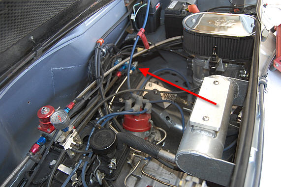 You can't see the valve cover lines, but they are underneath. You can't see the valve cover lines, but they are underneath. |
|
|
|
| ww914 |
May 18 2014, 02:11 PM
Post
#17
|
|
914 Convert Group: Members Posts: 435 Joined: 29-September 11 From: Central Coast, CA Member No.: 13,621 Region Association: Central California |
[/quote]
Yup, that is blocking,airflow. [/quote] Believe it works better mounted on the rear truck. You can't see the valve cover lines, but they are underneath. [/quote] Without re-building the box, I could only move it to where the old air pump resided. It seems to have worked OK at the AX yesterday and it appears to have as least as much room for air to get to the blower as the original set up. Also, I have it mounted a little higher for better drainage back to the case.  |
|
|
|
| yeahmag |
May 19 2014, 12:14 PM
Post
#18
|
|
Advanced Member Group: Members Posts: 2,421 Joined: 18-April 05 From: Pasadena, CA Member No.: 3,946 Region Association: Southern California |
Jake and Len had a big write up on this, but I experienced something on my own motor that prompted me to make the change in the new build. My motor "ran out of oil" at a track day with PCA without ever leaking a drop. The theory is that the central breather failed (my original one was janky at best) and allowed the heads to operate at a lower pressure than the case, so the oils flow rate was reduced back from the heads to the case - essentially filling the heads with oil.
The ideas of a large central chimney and no head vents is just the reverse. Any pressure that builds in the heads must vent back through the case. This should help encourage any oil in the heads to find it's way back to the case. I believe the 911 motors are set up the same way. -Aaron QUOTE(ww914 @ May 17 2014, 08:53 PM) Aaron Please explain this a little further. It kinda makes sense to me, but I am not sure I fully get it. Am I under the possible mistaken opinion that all three hoses, case and both heads, help to equalize the pressure. Sounds to me just having the one drain hose, the can is just what it implies, a catch can for oil, or is it that it does help by letting the case breath better? So, I think you are saying that without the head hoses, the head pressure actually helps send the oil back to the case. Is that right? Is that what you mean when you say that that is what Jake and Len determined? |
|
|
|
|
1 User(s) are reading this topic (1 Guests and 0 Anonymous Users)
0 Members:

|
Lo-Fi Version | Time is now: 5th May 2024 - 11:15 AM |
Invision Power Board
v9.1.4 © 2024 IPS, Inc.