|
|
|
Porsche, and the Porsche crest are registered trademarks of Dr. Ing. h.c. F. Porsche AG.
This site is not affiliated with Porsche in any way. Its only purpose is to provide an online forum for car enthusiasts. All other trademarks are property of their respective owners. |
|
|


| john77 |
 Jul 25 2014, 06:18 PM Jul 25 2014, 06:18 PM
Post
#1
|
|
Senior Member  Group: Members Posts: 621 Joined: 21-February 14 From: Los Angeles Member No.: 17,027 Region Association: Southern California |
My sender stopped working and when I took it apart I found the resistance wire had snapped (this may or may not have been as a consequence of something stupid I did (IMG:style_emoticons/default/smile.gif) ).
I searched here first and couldn't find anything, so figured I'd post this fix in case anyone has the same problem in the future. As much as I'd like to take credit, it was largely informed by this post on The Samba The wire in the sender is nichrome, a high-resistance wire. 12 inches of the broken wire from the sender read approx. 42-43ohm on my multimeter. So, all you'll need is: 1. Soldering Iron 2. Solder 3. 42.2 ohm, 38 gauge nichrome wire for $3 from Jacobs Online Step 1: Use your soldering iron to heat and remove the solder attaching the ends of the snapped nichrome wire to the sender. Once you've removed the remaining pieces of wire, keep going until you've also removed all the old solder - underneath you'll find a hole in each of the tabs to thread the new wire through. 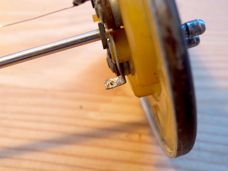 Step 2: The nichrome wire comes on a cardboard spool. Remove enough of it to go from one tab down to the bottom of the sender and back up again + about 5 inches. Pull it through your fingers a couple of times to straighten out any kinks - it doesn't have to be perfectly flat. 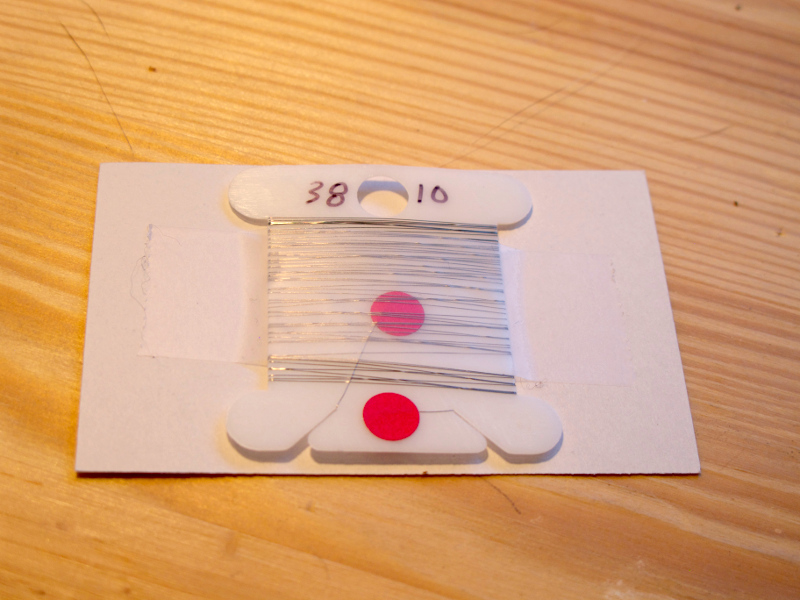 Step 3: Thread one end through the hole in one of the tabs you removed the old wire from. Pull an inch or so back on itself and then hold taut as you solder it in place. 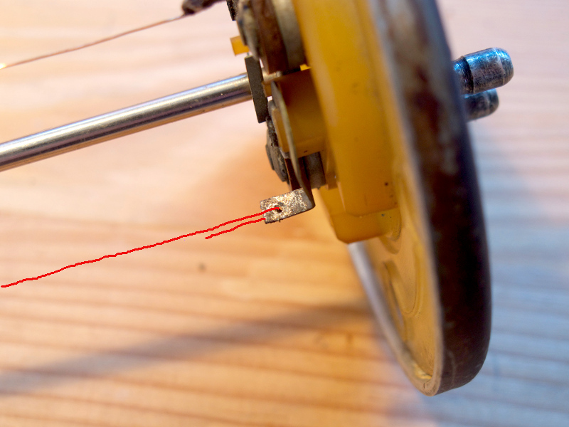 Step 4: Thread the wire through the metal contacts on the side of the float... 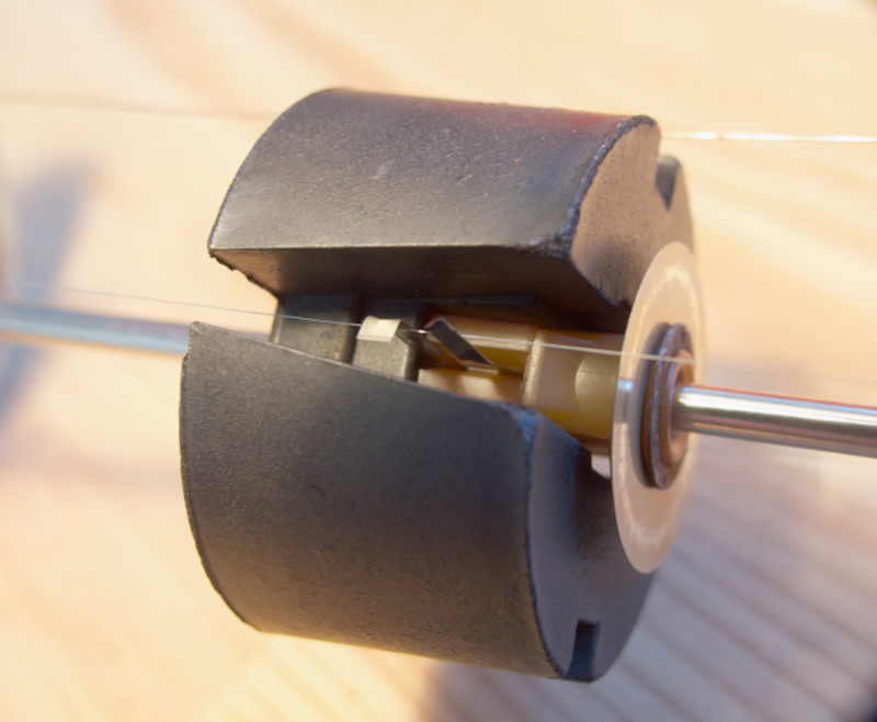 Step 5: ... and then down and around the black plastic piece at the bottom of the sender ensuring it doesn't touch the metal post (as in pic). 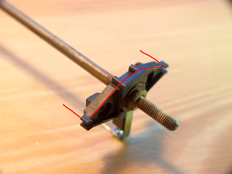 Step 6: Now, going back up toward the top of the sender, thread it through the metal contacts on the other side of the float (so same as Step 4)... Step 7: ... and through the hole in the opposite tab, again pulling back on itself to ensure it's taut, and then solder in place. Once it's cooled you can cut off the extra pieces of nichrome wire either side of the solder on the tabs and reassemble the sender. Then simply test your solders are good by either reconnecting it to the gauge and inverting the sender while still out of the tank to check the needle moves or, if you have a multimeter, connecting it to the two left pins (diagram below) on the top of the sender and watching the ohms increase/decrease as you slide the float up and down. 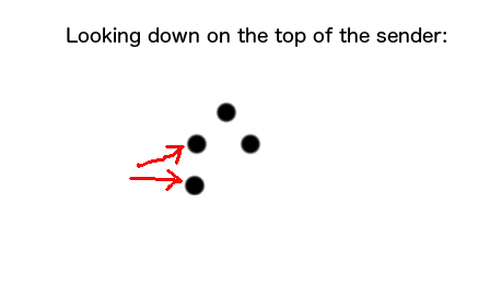 One final thing, when soldering be careful not to accidentally touch/burn the copper wire that runs the length of the sender and grounds the warning light... (IMG:style_emoticons/default/headbang.gif) If you do, a simple fix is to strip the insulation off a piece of electrical wire, remove the copper wire from inside and solder one strand of it in place of the broken copper wire. John |
   |

 
|
Posts in this topic
 john77 Broken Fuel Sender resistance wire Jul 25 2014, 06:18 PM
 BIGKAT_83 Good job on this.
Thanks for the write up. :trop... Jul 25 2014, 08:17 PM
BIGKAT_83 Good job on this.
Thanks for the write up. :trop... Jul 25 2014, 08:17 PM
 john77
Good job on this.
Thanks for the write up. :tro... Jul 25 2014, 10:45 PM bdstone914 With new fuel sender costing about $160 that ... Jul 25 2014, 09:16 PM john77
With new fuel sender costing about $160 that... Jul 25 2014, 10:50 PM john77 This has now also got me wondering if you couldn... Jul 26 2014, 06:17 AM effutuo101
My sender stopped working and when I took it apar... May 2 2018, 06:05 PM Jeff Bowlsby My fuel gauge pointer bounces and sticks pretty re... May 2 2018, 06:11 PM effutuo101
My fuel gauge pointer bounces and sticks pretty r... May 2 2018, 06:19 PM Mueller The nichrome wire is great for a heating element i... May 2 2018, 06:14 PM
john77
Good job on this.
Thanks for the write up. :tro... Jul 25 2014, 10:45 PM bdstone914 With new fuel sender costing about $160 that ... Jul 25 2014, 09:16 PM john77
With new fuel sender costing about $160 that... Jul 25 2014, 10:50 PM john77 This has now also got me wondering if you couldn... Jul 26 2014, 06:17 AM effutuo101
My sender stopped working and when I took it apar... May 2 2018, 06:05 PM Jeff Bowlsby My fuel gauge pointer bounces and sticks pretty re... May 2 2018, 06:11 PM effutuo101
My fuel gauge pointer bounces and sticks pretty r... May 2 2018, 06:19 PM Mueller The nichrome wire is great for a heating element i... May 2 2018, 06:14 PM  |
1 User(s) are reading this topic (1 Guests and 0 Anonymous Users)
0 Members:

|
Lo-Fi Version | Time is now: 18th May 2024 - 12:41 AM |
Invision Power Board
v9.1.4 © 2024 IPS, Inc.