|
|
|
Porsche, and the Porsche crest are registered trademarks of Dr. Ing. h.c. F. Porsche AG.
This site is not affiliated with Porsche in any way. Its only purpose is to provide an online forum for car enthusiasts. All other trademarks are property of their respective owners. |
|
|

  |

| timothy_nd28 |
 Sep 20 2014, 11:49 AM Sep 20 2014, 11:49 AM
Post
#41
|
|
Advanced Member  Group: Members Posts: 2,299 Joined: 25-September 07 From: IN Member No.: 8,154 Region Association: Upper MidWest |
Absolutely using the original sender, everything will be plug and play after the modification
|
   |

 
|
| Dr Evil |
Sep 20 2014, 12:20 PM
Post
#42
|
|
Send me your transmission! Group: Members Posts: 23,044 Joined: 21-November 03 From: Loveland, OH 45140 Member No.: 1,372 Region Association: MidAtlantic Region |
Badass!
|
|
|
|
| skeates |
Sep 20 2014, 03:55 PM
Post
#43
|
|
Member Group: Members Posts: 219 Joined: 28-February 05 From: Sacramento, ca Member No.: 3,684 Region Association: Northern California |
QUOTE(Dr Evil @ Sep 20 2014, 07:04 AM)  While I dig the scholastic effort in figuring out the step frequency and such, I must wonder if the modification of a stock 914 fuel gauge into the panel would not be loads simpler as you can then use the stock sender, and tank, and..... However, I in no way wish to dissuade you from the path you have chosen as it is very interesting (IMG:style_emoticons/default/smile.gif) Thanks for the suggestions! I do happen to have my old fuel gauge hanging out in the garage. I've just hesitated to take it apart since it's a perfectly functional stock gauge that someone might want. If my own attempts to build this circuit fail, I'll likely use that as my fall back. QUOTE(timothy_nd28 @ Sep 20 2014, 07:08 AM) No, the voltages do not oscillate as in a motor, but rather each coil generates a magnetic field, and being at 90 degrees of each other, generate a magnetic field at an angle of atan(I coil1/I coil2). So you can achieve deflection of +/-45 degrees with a current level from 0 to max in coil1 (simultaneously changing current in coil2 from max to 0). There is a bar magnet on the needle which aligns with this field, causing the needle to move. Try to solder wires on the motor pins and re-assemble to run the test and take measurements. Interesting. I'll see what I can do about getting some wires soldered on. We just moved and I no longer have a 240V outlet for my soldering iron (was "junk" being thrown away from an INTEL factory overseas). It's perfect for this stuff, but I need to get a power supply or install an outlet for it. In the mean time it looks like I have some reading up to do on driving air-core motors. Thanks for the link! Should have some progress to report later tonight! |
|
|
|
| timothy_nd28 |
Sep 20 2014, 04:49 PM
Post
#44
|
|
Advanced Member Group: Members Posts: 2,299 Joined: 25-September 07 From: IN Member No.: 8,154 Region Association: Upper MidWest |
We will help you with the calculations needed for the resistors needed to drive this air core motor with the stock fuel gauge sender, don't worry about that.
|
|
|
|
| Dr Evil |
Sep 20 2014, 05:20 PM
Post
#45
|
|
Send me your transmission! Group: Members Posts: 23,044 Joined: 21-November 03 From: Loveland, OH 45140 Member No.: 1,372 Region Association: MidAtlantic Region |
The link on wiki has some suggestions for driver chips, too (IMG:style_emoticons/default/smile.gif) I have faith that you will be able to get the stuff you have to work. I likely have the guts from a stock fuel gauge if you end up going that route. No need to destroy a good one.
|
|
|
|
| skeates |
Sep 21 2014, 04:09 PM
Post
#46
|
|
Member Group: Members Posts: 219 Joined: 28-February 05 From: Sacramento, ca Member No.: 3,684 Region Association: Northern California |
QUOTE(904svo @ Sep 19 2014, 07:14 PM) From the reading you have a stepper motor gas gauge, you could try to set your pot to give a full reading on one set of the windings and another pot with reversed battery and ground to give a empty reading ( gas gauge sender ). Yup! Was banging my head quite a bit yesterday trying to interpret my measurements when I finally decided to challenge the assumption that this was indeed an air-core motor. Switched up the code and tried driving it like a stepper motor....and....success! This explains the transient voltage measurements I was getting while the gauge was moving. I need to play with the code a bit to see if I can get it to step in 1/2 increments since right now it's a pretty rough movement, but here's a video of it sweeping from empty to full: https://www.youtube.com/watch?v=V8I68EIvCgI |
|
|
|
| stugray |
Sep 21 2014, 04:36 PM
Post
#47
|
|
Advanced Member Group: Members Posts: 3,825 Joined: 17-September 09 From: Longmont, CO Member No.: 10,819 Region Association: None |
Great work!
On a slightly related note: Just today I got my arduino datalogger working. It can read 8 analog voltage inputs, rpm (from a standard points setup or MSD 12V tach signal), and serial data from an innovate system. It then logs data to microSD, and outputs it over USB to be displayed by a droid phone. It also can control one "alarm light" and a shift light. So with what you have reverse engineered here, you could easily plug that instrument cluster onto my arduino DL and drive all of the interfaces on the cluster while logging data... hmmm.... (IMG:style_emoticons/default/idea.gif) |
|
|
|
| skeates |
Sep 22 2014, 12:37 AM
Post
#48
|
|
Member Group: Members Posts: 219 Joined: 28-February 05 From: Sacramento, ca Member No.: 3,684 Region Association: Northern California |
QUOTE(Dr Evil @ Sep 20 2014, 04:20 PM) The link on wiki has some suggestions for driver chips, too (IMG:style_emoticons/default/smile.gif) I have faith that you will be able to get the stuff you have to work. I likely have the guts from a stock fuel gauge if you end up going that route. No need to destroy a good one. Thanks for the encouragement (and the parts)! Not sure anymore if the stock fuel gauge guts can be made to work since it's a stepper motor? I'm sure that there's got to be a pretty snazzy hardware solution to this. QUOTE(stugray @ Sep 21 2014, 03:36 PM) Great work! On a slightly related note: Just today I got my arduino datalogger working. It can read 8 analog voltage inputs, rpm (from a standard points setup or MSD 12V tach signal), and serial data from an innovate system. It then logs data to microSD, and outputs it over USB to be displayed by a droid phone. It also can control one "alarm light" and a shift light. So with what you have reverse engineered here, you could easily plug that instrument cluster onto my arduino DL and drive all of the interfaces on the cluster while logging data... hmmm.... (IMG:style_emoticons/default/idea.gif) That sounds way cool - and totally doable! The gauges/motors are all mounted on a separate plastic frame which can be separated very cleanly from the circuit board. The only thing you'll loose are the LCD displays if you chuck the board. That said, the other gauges were really easy to make work without any ECU trickery (just standard signals). The fuel gauge is the only "problem" piece to this whole puzzle. So - you might be better off keeping the Boxster cluster electronics in there and just isolating the pins on the fuel gauge. That way you can keep the digital speedo, clock, and odometer. And, on that note, I had a breakthrough this evening and now have things worked out to control the fuel level using a potentiometer! The motor itself is still controlled by an arduino which takes as an input the voltage across the potentiometer. Added a rudimentary smoothing function to try and smooth out the signal, but as you can see in the video there are still some bugs in the software. One thing I'd like to figure out is whether or not there is a way to" zero" the motor without bumping it off its bottom stop. I the long run I can live with it, but It would be nice to not have it do a bouncy jig at the bottom of the gauge every time I turn the ignition on. Anyways - concept is there, now comes the fun bit of converting the concept into a practical application. https://www.youtube.com/watch?v=QfSpp4YkERY |
|
|
|
| CptTripps |
Sep 22 2014, 07:59 AM
Post
#49
|
|
:: Punch and Pie :: Group: Members Posts: 3,586 Joined: 26-December 04 From: Tuscaloosa, AL and Akron, OH Member No.: 3,342 Region Association: Upper MidWest |
That's just bad ass....
|
|
|
|
| timothy_nd28 |
Sep 22 2014, 11:20 AM
Post
#50
|
|
Advanced Member Group: Members Posts: 2,299 Joined: 25-September 07 From: IN Member No.: 8,154 Region Association: Upper MidWest |
Awesome! Sorry for sending you down a wrong path, it makes perfect sense now
|
|
|
|
| Scott S |
Sep 22 2014, 12:01 PM
Post
#51
|
|
Small Member Group: Members Posts: 1,698 Joined: 30-April 03 From: Colorado Member No.: 633 |
Wow. I have never felt dumber. There are some smart folks on this site!
Cool stuff!! (IMG:style_emoticons/default/beerchug.gif) |
|
|
|
| skeates |
Sep 22 2014, 12:05 PM
Post
#52
|
|
Member Group: Members Posts: 219 Joined: 28-February 05 From: Sacramento, ca Member No.: 3,684 Region Association: Northern California |
QUOTE(timothy_nd28 @ Sep 22 2014, 10:20 AM) Awesome! Sorry for sending you down a wrong path, it makes perfect sense now No worries - all of the feedback was helpful! Even learned a ton about air-core motors in the process. It's great having the support and experience of this community while tackling things that are just a bit (sometimes more than a "bit") over my head! (IMG:style_emoticons/default/beer.gif) |
|
|
|
| Dr Evil |
Sep 23 2014, 07:15 AM
Post
#53
|
|
Send me your transmission! Group: Members Posts: 23,044 Joined: 21-November 03 From: Loveland, OH 45140 Member No.: 1,372 Region Association: MidAtlantic Region |
Not that it matters now, since you have been experiencing success with your interface using the Arduino, but what I was referring to with the use of the OE gauge guts was to place the guts behind the gauge face in place of the original, put the Boxter needle on the shaft of the OE unit, and then use the original tank sender. I see this as simple, but not nearly as much fun, nor elegant (IMG:style_emoticons/default/wink.gif) The problems I foresee doing this are possible length of shaft of OE too short, needle wont work on shaft, sweep ark of OE not same as Boxter and thus gauge face will not be correct measurement/needle deflection will be incorrect, OE guts will not fit.
With your initial start up causing needle bounce, is it possible to have a value programmed in to make the needle hold a value consistent with the E at start up? How bout Full and then is drops to actual? Is this bounce of the needle stop due to poor or no signal? Does the stock setup in a Boxter do this, or is this just due to your interface? How about a delay in the interface that allows it to power up before sending a signal to the gauge so that there is no "seizure" on start up? |
|
|
|
| DRPHIL914 |
Sep 23 2014, 07:31 AM
Post
#54
|
|
Dr. Phil Group: Members Posts: 5,950 Joined: 9-December 09 From: Kennesaw, GA Member No.: 11,106 Region Association: South East States |
QUOTE(Scott S @ Sep 22 2014, 02:01 PM) Wow. I have never felt dumber. There are some smart folks on this site! Cool stuff!! (IMG:style_emoticons/default/beerchug.gif) LOL for sure- i was thinking the same thing, now i wish i had taken more electrical classes!! some think "ohm" is what you say when meditating --- i guess my brain has too much "resistance" to learning this type of stuff - (IMG:style_emoticons/default/huh.gif) but i get the big picture, - very interested to how this all pans out!! |
|
|
|
| ruby914 |
Sep 23 2014, 10:02 AM
Post
#55
|
|
Senior Member Group: Members Posts: 720 Joined: 26-April 09 From: Hawthorne, Ca Member No.: 10,305 Region Association: None |
Nice work Skeates!
The Boxter cluster up against the OE bezel looks great. The cluster looks nice and small, the biggest problem may be the depth. I don't recall how much room you have to work with, the Boxter looks small but deep. For the bottom you could trim some off the lower dash sub frame and remove or remake the top loop. I removed my top loop and the cluster mounts to the bottom of the dash. It seems like, with a custom bezel, it would look great in the OE dash. What motor is going in this car? (IMG:style_emoticons/default/popcorn[1].gif) Attached image(s) 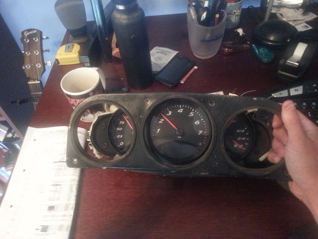
|
|
|
|
| skeates |
Sep 23 2014, 10:57 AM
Post
#56
|
|
Member Group: Members Posts: 219 Joined: 28-February 05 From: Sacramento, ca Member No.: 3,684 Region Association: Northern California |
QUOTE(Dr Evil @ Sep 23 2014, 06:15 AM) Not that it matters now, since you have been experiencing success with your interface using the Arduino, but what I was referring to with the use of the OE gauge guts was to place the guts behind the gauge face in place of the original, put the Boxter needle on the shaft of the OE unit, and then use the original tank sender. I see this as simple, but not nearly as much fun, nor elegant (IMG:style_emoticons/default/wink.gif) The problems I foresee doing this are possible length of shaft of OE too short, needle wont work on shaft, sweep ark of OE not same as Boxter and thus gauge face will not be correct measurement/needle deflection will be incorrect, OE guts will not fit. With your initial start up causing needle bounce, is it possible to have a value programmed in to make the needle hold a value consistent with the E at start up? How bout Full and then is drops to actual? Is this bounce of the needle stop due to poor or no signal? Does the stock setup in a Boxter do this, or is this just due to your interface? How about a delay in the interface that allows it to power up before sending a signal to the gauge so that there is no "seizure" on start up? That's a good suggestion as it sidesteps the need to get elbow deep in electronics and coding. Since I followed this route I'm not sure about how well OE motor would fit into the Boxster cluster's frame. It's pretty tight in there and the whole assembly would need to fit neatly sandwiched between the face and the electronics board. If I can get those spare internals from you (and folks are interested), I can mock it up to see how well things fit - I imagine it'll be pretty obvious once one puts them next to each other. On the needle bounce - from what I gather it's somewhat of an evil necessity for an open loop stepper motor system. I believe that the boxster cluster has some pretty sophisticated electronics that can keep better track of the needle position, but it still has to zero the needle - though it doesn't seem to bounce the way mine does. I think it has to do with the fact that the OEM electronics are able to drive the motor in mircro-steps rather than in the half-steps that I am limited to. Last night I did a bit of research on stepper motor integrated circuits as I'd like to fashion a better hardware solution than what I currently have. If I can get that working it should be pretty easy to reproduce for interested folks. Obviously I would also post all the info hear for anyone wanting to DIY. QUOTE(ruby914 @ Sep 23 2014, 09:02 AM) Nice work Skeates! The Boxter cluster up against the OE bezel looks great. The cluster looks nice and small, the biggest problem may be the depth. I don't recall how much room you have to work with, the Boxter looks small but deep. For the bottom you could trim some off the lower dash sub frame and remove or remake the top loop. I removed my top loop and the cluster mounts to the bottom of the dash. It seems like, with a custom bezel, it would look great in the OE dash. What motor is going in this car? (IMG:style_emoticons/default/popcorn[1].gif) I wish I had my OEM dash cap up here to check the fit of this cluster in the stock dash. I don't think depth will be an issue as it's not that much different than the stock gauges. Plus, the plugs have a much lower profile so one get's a little more room because of that. I think the difficult part is height. The indicator lights on the Boxster cluster stick out just below the OEM mounting face and I think the clearance issue would be with the top of the steering column rather than the dash subframe. But, if there is some wiggle room on top one might just need to build a custom bezel and be done! BTW, the car has a suby EZ36 in it - though I still have to fab exhaust and get it a computer before I can turn it on. My build thread is here. |
|
|
|
| Dr Evil |
Sep 23 2014, 05:52 PM
Post
#57
|
|
Send me your transmission! Group: Members Posts: 23,044 Joined: 21-November 03 From: Loveland, OH 45140 Member No.: 1,372 Region Association: MidAtlantic Region |
All of my shit is in boxes in the back of a truck heading to OH. If you decide you want to try my method, I will dig for and send you the guts (IMG:style_emoticons/default/smile.gif)
Looking forward to more electronic hi jinx (IMG:style_emoticons/default/popcorn[1].gif) Why not just remove the stop pin for the fuel gauge? (IMG:style_emoticons/default/wink.gif) |
|
|
|
| Chris914n6 |
Sep 25 2014, 02:27 AM
Post
#58
|
|
Jackstands are my life. Group: Members Posts: 3,539 Joined: 14-March 03 From: Las Vegas, NV Member No.: 431 Region Association: Southwest Region |
Cluster fit doesn't look too far off. The loop will have to be cut off but the top pad will flex a bit. There is room to trim the dash before you hit chassis.
The 914 fuel sender is a pretty common 0-90 ohm. GM standard, and my 90's Nissan cluster work with it, so there are options for a donor motor. |
|
|
|
| purple505uk |
Oct 26 2015, 02:07 PM
Post
#59
|
|
Newbie Group: Members Posts: 1 Joined: 26-October 15 From: ravenshead Member No.: 19,300 Region Association: None |
QUOTE(skeates @ Sep 15 2014, 07:07 PM) So, until someone tells me this is cluttering up the web I'm going to keep posting my progress (IMG:style_emoticons/default/evilgrin.gif). Made a bit more progress on the boxster gauge cluster this weekend. First things first; even though I'm making a custom dash cap I figured I'd check to see how close this thing fits within the stock set-up. I figured if it fits that would open up a world of opportunities to those wanting to update their gauges, and stick with the Porsche feel without having to make a custom dash. So...I dug out the mounting plate for the stock gauges just to see how close the fit was (see first pic). It's hard to see in the picture, but there are two issues as I can tell which would make it difficult (though not necessarily impossible) to use this with the stock dash cap. 1) The toggles on the top of the cluster (for setting the clock, adjusting brightness, etc.) line up just about perfectly with the two top mounting screw holes. This wouldn't be too hard to work around since you'd be fabricating a custom surround to mount the gauges. At that time just move/make new tabs on the dash frame that line up. Done. 2) The second issue may be somewhat more difficult to work around. Looking at the bottom of the picture you can see that the pod housing the warning lights sticks out slightly below the bottom of the mounting plate. The boxster cluster is just a little bit too tall from what I can tell to fit within the stock dash cap - but it's such a close fit! So close that without an actual dash cap to play with I can't make any final conclusions on the possibility of making this thing fit with the stock dash cap. (if anyone wants to head up to Truckee, Ca with a stock cap to test this out with feel free to swing by (IMG:style_emoticons/default/biggrin.gif) ) So, onto the fun stuff - electricity! I've spent more time then I care to think about tracing the boxster wiring diagrams and trying to piece together what's needed and what's not. There are several power inputs, (2) which are constant +12V and (3) more which are powered when the key is in the ACC/Drive position in the ignition. Also, there are (2) grounds for the cluster and an additional "ground" for the sender units (fuel, coolant temp, etc). In order to keep strait the mess of wires I manually pinned out and labeled each wire through the connectors. While doing so I found that many of the expected wires/inputs were "missing" from my pins. Some of these are for inputs from the tiptroic transmission which I expect to be missing on a manual cluster. Others though I think are related to the on-board computer option. At this point I'm just worried about basic functionality, so I'm not paying a whole lot of attention to the missing inputs, but they may become important later if the cluster is expecting an input that I'm not delivering. Note my pig-tails are out of a different '97 manual boxster than the gauge cluster, so there could be some miss-match happening if the options on the cars were different. Below there's a picture of my test-rig (basically just a bread board to facilitate quick & easy circuits and and arduino board that I'm using as a signal generator to simulate speedo and tach signals. With the gauge cluster powered I then went through at tested the voltage at each (well most anyways) wire to see if any were powered. After doing this I found out something very interesting - most of the indicator lights, the speedo signal, and the tach signal are all powered and expect a ground as their "input". In the case of the speedo and tach they need to be pulled down to ground at a certain frequency, like a flickering light switch, which corresponds to the speed of the car/engine. I'm not sure whether or not this is "normal" for these types of signals, but I was expecting to have to produce a +12V signal to each, not a ground. It actually made it easier in a sense since all I needed to do was use a general purpose transistor as a switch and feed it a PWM signal from the arduino. I addition to those signals, I also got some potentiometers out to simulate the coolant temp and fuel senders. The pic below shows everything running...sort of... So, the moral of this story is that I've been able to get all the basic functionality working! I've got an Excel spreadsheet I use to calculate at what frequency the PWM signal needs to operate to simulate a specific MPH or RPM. I've also got the coolant temp gauge sender resistance values figured out, the gauge back-lighting/dimming is working, indicator lights are all functional, as well as the turn-signals/high beam indicators, etc.. But....and so far it's been a big pain in the butt....the damn fuel gauge is only sort-of working and represents the final piece to this puzzle. The top 3/4 of the fuel gauge range works flawlessly with a 0 - 400 Ohm potentiomter. However, as soon as you get to ~ 400 Ohms (just less than 1/4 tank) the fuel gauge drops to empty and the low fuel indicator light starts flashing. Doing some reading I found that on the 996 C4's the gas tanks were designed such that a sender wouldn't fit all the way down and then the gauge had to switch over to some sort of internal calculation approach using fuel consumption data from the ECU to estimate fuel tank levels below 12 litres. I didn't get the sense though that this was true of the C2's or the Boxters. Something definitely happens at the 1/4 tank mark where the gauge stops listening to the sender signal. In fact, once it hits that mark I can no longer get the needle to move at all by changing the resistance values. I have to do a full reset on the cluster (un-plug and plug back in) to get it to listen again. I figure it has to be looking for a signal that I'm not giving it right now, and I think I've isolated it to one or two wires: 1) There is a fuel tank status wire going to the DME (ECU) which I thought was an output, but now I'm wondering if it's an input. It has no voltage when the cluster is powered. 2) There is a wire labeled "KVA DME" on the cluster diagrams, but on the DME wiring diagram it's labeled "fuel consumption indicator". I think this one may be the missing piece, but I have no idea what signal it's sending. On the cluster this wire measures +10 V (same as the speedo and tach wires) which makes me think its looking for a similar signal to ground. My current guess it that it will somehow correspond to the fuel injector pulse signal. If anyone has any ideas (or information) on how to get the last quarter of the fuel gauge working I'd LOVE the input. It's the last 10% that takes 90% of the time/effort! Great work! Im not the best at electronics and need to power up the lower lcd screens on the same 986 dash can you tell me what voltage i need 12v DC or Ac? , and which colour plugs and which pins do I need to supply this voltage too? Also which ones do i need to ground? Ive tried to work it out from you pic , I cannot tell very well from there, your help is massively appreciated sorry to be a noob!! |
|
|
|
| wasz |
Aug 12 2025, 02:29 PM
Post
#60
|
|
Newbie Group: Members Posts: 1 Joined: 11-August 25 From: uk Member No.: 28,918 Region Association: None |
10 years have gone by - but do you happen to have the arduino sketch and circuit diagram you used for this? I'm thinking of going down the same road?
|
|
|
|
|
1 User(s) are reading this topic (1 Guests and 0 Anonymous Users)
0 Members:

|
Lo-Fi Version | Time is now: 13th July 2026 - 01:00 AM |
Invision Power Board
v9.1.4 © 2026 IPS, Inc.