|
|
|
Porsche, and the Porsche crest are registered trademarks of Dr. Ing. h.c. F. Porsche AG.
This site is not affiliated with Porsche in any way. Its only purpose is to provide an online forum for car enthusiasts. All other trademarks are property of their respective owners. |
|
|

  |

| Java2570 |
 Aug 19 2014, 08:43 AM Aug 19 2014, 08:43 AM
Post
#21
|
|
Senior Member  Group: Members Posts: 649 Joined: 7-May 11 From: Fishers, IN Member No.: 13,035 Region Association: Upper MidWest |
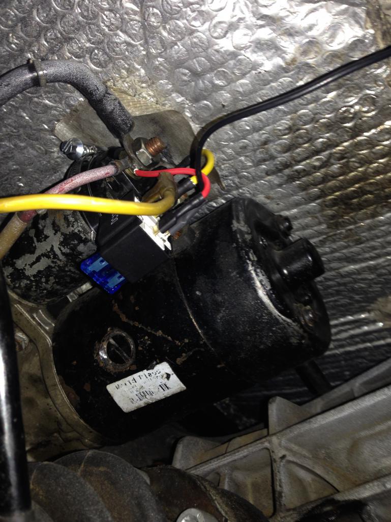
Here is a photo of my install of this relay kit.....clamp onto solenoid, yellow wire from relay goes to top solenoid connector, red wire from relay goes to starter + lug, black wire goes to same ground as trans ground strap, yellow wire from ignition (that previously was connected to solenoid) goes to relay. I thought about the Ford relay setup but I found not much detail in how it is wired and I'm already electrically challenged as it is.....by the time I'd have bought the parts to do the Ford setup and spent all the time and effort wiring it, I'd have spent more than $30 in money and frustration. So I went with McMark's setup.....
 |
   |

 
|
| Cap'n Krusty |
Aug 19 2014, 08:48 AM
Post
#22
|
|
Cap'n Krusty Group: Members Posts: 10,794 Joined: 24-June 04 From: Santa Maria, CA Member No.: 2,246 Region Association: Central California |
QUOTE(SLITS @ Aug 19 2014, 07:42 AM)  QUOTE(malcolm2 @ Aug 19 2014, 06:12 AM) Sorry Stu, but I don't follow exactly. At first you said the wires were the wrong size, but then you never gave a size and you mention the battery cable in 2 places.... (IMG:style_emoticons/default/blink.gif) do you mean to use a wire the same size as the car's battery wire? The video was interesting, but raised more thoughts and questions. So, I doctored the napkin drawing. Can anyone confirm my questions in GREEN ? The wire size from the battery to the solenoid, whether it is the stock solenoid on the starter or the Ford is #2 or #4 ... easily said it is a battery cable. The same size wire is used from the Ford solenoid to the existing stock solenoid. It carries High amperage. You can purchase a short battery cable with eye ends from most any FLAPS. The only light gauge wire (16?) is used from the output of the Ford Solenoid to the spade terminal on the stock solenoid. You have to activate the stock solenoid to get the Bendix gear to engage the flywheel so the motor will turn. So, in reference to your diagram ... the answers are YES on the wire sizes. If my car was on the rack I would shoot an image. Your diagram introduces another unnecessary connection in the wiring from both the alternator and the battery, something that can degrade the voltage and current to the starter. Essentially, that's part of what we're trying to correct by adding the solenoid. As I said above, leave the 12v + (30) cables on the outboard post of the solenoid. The Cap'n |
|
|
|
| Dtjaden |
Aug 19 2014, 08:55 AM
Post
#23
|
|
Member Group: Members Posts: 232 Joined: 25-May 13 From: Morgan Hill, CA Member No.: 15,915 Region Association: Northern California |
The battery and alternator wires should remain on the 914 starter. The yellow wire, +12 from the ignition switch, should be wired as you have it. A new wire, same size as the yellow wire, should go from the post on the 914 starter where the battery and alternator wires are connected. A new wire, again same gauge as the yellow wire, should go as you have it connected to where the yellow wire was on the 914 starter. Finally, you need a new wire connected from the other upper post on your drawing to a ground.
Now, I have a concern about using the Ford "relay". This is a very large relay that is often called a starter solenoid. It may draw as much current to activate as the 914 starter. McMark's solution uses a relay that only requires very low current when activated. If you have an ohm meter you can check this out by: 1) check the resistance between the two top terminals on your drawing - this is the relay coil; 2) on the 914 starter check the resistance between the post where the yellow wire connects and ground. If the resistance on the Ford relay is not MUCH higher you have not really gained any advantage using the Ford relay. |
|
|
|
| malcolm2 |
Aug 19 2014, 09:04 AM
Post
#24
|
|
Advanced Member Group: Members Posts: 2,745 Joined: 31-May 11 From: Nashville Member No.: 13,139 Region Association: South East States |
Thanks Cap'n. In this picture of one I believe that Mark Henry did in another post the engine is out of the car. But it looks like the large post nut on the starter solenoid is loose. I assumed that he had the BATT + and Alt here, you confirmed that. The dude in the video gave me the question about attaching those to the new FORD Relay.
Also I saw a post from you in my searches about the 6 V relay. I wondered why and if you mis-typed, but now I know. I might just return the NAPA 12v I have and look for a 6V one. Once again, thanks. Clark 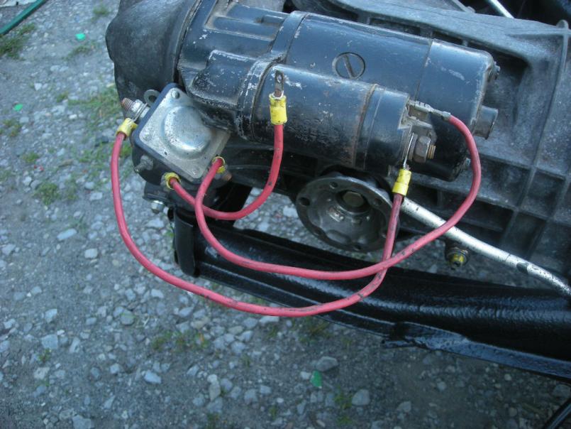 |
|
|
|
| malcolm2 |
Aug 19 2014, 09:18 AM
Post
#25
|
|
Advanced Member Group: Members Posts: 2,745 Joined: 31-May 11 From: Nashville Member No.: 13,139 Region Association: South East States |
QUOTE(Dtjaden @ Aug 19 2014, 09:55 AM) The battery and alternator wires should remain on the 914 starter. The yellow wire, +12 from the ignition switch, should be wired as you have it. A new wire, same size as the yellow wire, should go from the post on the 914 starter where the battery and alternator wires are connected. A new wire, again same gauge as the yellow wire, should go as you have it connected to where the yellow wire was on the 914 starter. Finally, you need a new wire connected from the other upper post on your drawing to a ground. I did not mention GROUND, you are correct. If the Ford relay is bolted to the stater, wouldn't that be the ground? I understood that 2nd small post was something Ford connected to the coil? (Ford guy told me that) There is an "I" on one small post and an "S" on the other. I plan on using the "S" for my YELLOW wire. And leaving the "I" empty. |
|
|
|
| Cap'n Krusty |
Aug 19 2014, 09:37 AM
Post
#26
|
|
Cap'n Krusty Group: Members Posts: 10,794 Joined: 24-June 04 From: Santa Maria, CA Member No.: 2,246 Region Association: Central California |
"S" = "switch", IIRC. On my bus, I mounted the relay (Ford solenoid) to the body. I've bolted them down with one of the long starter through bolts on 914s, and to the firewall tin, as well.
The Cap'n |
|
|
|
| Mblizzard |
Aug 19 2014, 10:57 AM
Post
#27
|
|
Advanced Member Group: Members Posts: 3,033 Joined: 28-January 13 From: Knoxville Tn Member No.: 15,438 Region Association: South East States |
Clark I still have that complete column with multiple keys if you need it.
I really like McMarks relay all the wiring is done! |
|
|
|
|
1 User(s) are reading this topic (1 Guests and 0 Anonymous Users)
0 Members:

|
Lo-Fi Version | Time is now: 1st June 2024 - 04:03 PM |
Invision Power Board
v9.1.4 © 2024 IPS, Inc.