|
|
|
Porsche, and the Porsche crest are registered trademarks of Dr. Ing. h.c. F. Porsche AG.
This site is not affiliated with Porsche in any way. Its only purpose is to provide an online forum for car enthusiasts. All other trademarks are property of their respective owners. |
|
|

  |

| malcolm2 |
 Oct 16 2014, 06:29 AM Oct 16 2014, 06:29 AM
Post
#21
|
|
Advanced Member  Group: Members Posts: 2,745 Joined: 31-May 11 From: Nashville Member No.: 13,139 Region Association: South East States |
QUOTE(Mblizzard @ Oct 15 2014, 08:44 PM)  Anyone figure out Clark is an engineer? I know some of the other gauges have some reference values printed al g the very top part of the gauge. Not sure if the combo is the same. This one does have those numbers. you need to take it out to see them and they are in Celsius. The red line starts at 156.7 then there is a slight tick mark 1/2 way across the red for 170. Thanks for the vote of confidence, but i am the type of engineer that the other engineers make jokes about, an industrial engineer. (IMG:style_emoticons/default/av-943.gif) |
   |

 
|
| malcolm2 |
Oct 20 2014, 09:15 PM
Post
#22
|
|
Advanced Member Group: Members Posts: 2,745 Joined: 31-May 11 From: Nashville Member No.: 13,139 Region Association: South East States |
QUOTE(timothy_nd28 @ Oct 15 2014, 07:43 PM) I'm not sure where the needle should point at 212 degree's F. I think it's too close to the red mark for such a low temp. If you buy a 1k potentiometer from your local radio shack, you could wire it in series with the sender. Perform the test again, and adjust the pot till the needle is somewhere in the middle. Then if you carefully remove the pot from the circuit and measure the resistance, you could buy a fixed resistor with that value and hard wire it in the circuit. Just a thought Hey Tim, I am back at it......I bought the 1k potentiometer and I get zero needle movement. I ran the pot screw thru all 15 turns and measured ohms from 0 to 1.5 on the continuity scale. 3 terminals on the pot. I put the wire from the sender to, let's say, the right term on the pot, then from the middle terminal on the pot to the gauge. The gauge was all powered up like above and the gauge needle was nearly 1/2 way. Do I need more resistance, a 20K or 100k pot? I wonder if Bruce is correct about a short in the gauge giving me more resistance at room temp. I did not see anything touching the "G" when I opened it up. Clark |
|
|
|
| timothy_nd28 |
Oct 20 2014, 10:04 PM
Post
#23
|
|
Advanced Member Group: Members Posts: 2,299 Joined: 25-September 07 From: IN Member No.: 8,154 Region Association: Upper MidWest |
You should test the potentiometer first. Measure the total resistance of the pot by checking the outer terminals, it should measure 1k (1000) ohms.
If this checks out fine, then put one meter lead to the middle pin, and the other meter lead on one of the 2 remaining pins (you choose). The pin that is not used, go ahead and bend it over so you don't get confused with it later. With the multimeter still on the resistance setting, observe what it is reading. Then turn the potentiometer fully in one direction, it will either read zero or 1000 ohms. Go ahead and turn it so it reads 0 ohms,,essentially a shorted state. If all of the above checks out, and the potentiometer is calibrated to 0 ohms, continue to the next step. As in post number 18, set it up the same exact way. The sensor casing is ground, and should share the same ground as the gauge ground and battery ground. The terminal on the sensor should be wired straight to the G terminal. Go ahead and boil a pot of water and verify everything still works as it did in post 18. If all checks out and works like it did earlier, then wire in the potentiometer. The terminal from the sensor needs to be wired to the middle pin on the pot. The other pin of the potentiometer needs a wire going to the G terminal on the gauge. With your multimeter, measure the resistance from the G terminal on the gauge to the terminal on the sensor. You should read 0 ohms. Now boil some water, and insert your sensor into this bath of water. Be sure that the sensor doesn't touch the sides or bottom of this boiling pot of water. You gauge should still reach the same red mark as you showed us in post #18. Now, adjust the potentiometer, by adding resistance, you should see the needle back off from the red mark. |
|
|
|
| timothy_nd28 |
Oct 20 2014, 10:19 PM
Post
#24
|
|
Advanced Member Group: Members Posts: 2,299 Joined: 25-September 07 From: IN Member No.: 8,154 Region Association: Upper MidWest |
I just did a quick Google search and it looks like the sensor for the combo temp gauge has a resistance of 3000 ohms (cold) to 1000 ohms (hot).
So the 1k pot that you bought should be about perfect. This is only temporary, as we are using this as a trim pot. After you adjust the pot to where you like the needle placement, go ahead and remove the potentiometer from the circuit and measure the resistance. Whatever you read, you will need to buy a 1/2 watt resistor that is close to that reading. |
|
|
|
| malcolm2 |
Oct 21 2014, 07:07 AM
Post
#25
|
|
Advanced Member Group: Members Posts: 2,745 Joined: 31-May 11 From: Nashville Member No.: 13,139 Region Association: South East States |
QUOTE(timothy_nd28 @ Oct 20 2014, 11:04 PM) You should test the potentiometer first. Measure the total resistance of the pot by checking the outer terminals, it should measure 1k (1000) ohms. If this checks out fine, then put one meter lead to the middle pin, and the other meter lead on one of the 2 remaining pins (you choose). The pin that is not used, go ahead and bend it over so you don't get confused with it later. With the multimeter still on the resistance setting, observe what it is reading. Then turn the potentiometer fully in one direction, it will either read zero or 1000 ohms. Go ahead and turn it so it reads 0 ohms,,essentially a shorted state. If all of the above checks out, and the potentiometer is calibrated to 0 ohms, continue to the next step. As in post number 18, set it up the same exact way. The sensor casing is ground, and should share the same ground as the gauge ground and battery ground. The terminal on the sensor should be wired straight to the G terminal. Go ahead and boil a pot of water and verify everything still works as it did in post 18. If all checks out and works like it did earlier, then wire in the potentiometer. The terminal from the sensor needs to be wired to the middle pin on the pot. The other pin of the potentiometer needs a wire going to the G terminal on the gauge. With your multimeter, measure the resistance from the G terminal on the gauge to the terminal on the sensor. You should read 0 ohms. Now boil some water, and insert your sensor into this bath of water. Be sure that the sensor doesn't touch the sides or bottom of this boiling pot of water. You gauge should still reach the same red mark as you showed us in post #18. Now, adjust the potentiometer, by adding resistance, you should see the needle back off from the red mark. With the exception of boiling the water again and MAYBE the bolded statement above. That is what I did. I am thinking I put the lead from the sensor on one of the outer terminals of the pot, but I am not positive. I'll double check that this evening. Why wouldn't the needle move with the pot. a room temp? I was measuring as I moved the pot and got a reading that was much higher than the reading I got from the sensor at room temp..... 1.8 on the continuity setting. IIRC I got 1.3 at room temp with no pot attached. I did document the sensor's readings at different temps up to 212. I'll run thru your test scenario tonight. Thanks for your input. |
|
|
|
| timothy_nd28 |
Oct 21 2014, 12:05 PM
Post
#26
|
|
Advanced Member Group: Members Posts: 2,299 Joined: 25-September 07 From: IN Member No.: 8,154 Region Association: Upper MidWest |
The boiling water is key for this setup. The potentiometer is adding resistance, which will only drive the needle counter clockwise. If the sensor is at room temp, the needle is already maxed out at cold, adjusting the potentiometer at this point will not have any effect on the needle, because the needle can't move any further in that one direction.
Be sure the potentiometer is calibrated for zero ohms, before you perform this test later tonight. When the sensor is in the boiling water, adjust the potentiometer just a tiny bit, my guess is that your adjustment will be between 1/2 to a full turn. It shouldn't take much. |
|
|
|
| malcolm2 |
Oct 21 2014, 12:46 PM
Post
#27
|
|
Advanced Member Group: Members Posts: 2,745 Joined: 31-May 11 From: Nashville Member No.: 13,139 Region Association: South East States |
QUOTE(timothy_nd28 @ Oct 21 2014, 01:05 PM) If the sensor is at room temp, the needle is already maxed out at cold, adjusting the potentiometer at this point will not have any effect on the needle, because the needle can't move any further in that one direction. That makes sense. But did not seem logical since the location of the needle, when the gauge is disconnected, is further to the left. I assumed I could "push" the needle more to the left....while connected and at room temp. (IMG:style_emoticons/default/blink.gif) Should be easy to try your suggestion, Clark |
|
|
|
| ClayPerrine |
Oct 21 2014, 12:56 PM
Post
#28
|
|
Life's been good to me so far..... Group: Admin Posts: 15,436 Joined: 11-September 03 From: Hurst, TX. Member No.: 1,143 Region Association: NineFourteenerVille |
Has anyone noticed that there is no ground return wire from the sender that is in the water? None of the pictures show it.
If you don't ground the sender, all of your tests will be incorrect. |
 |
|
| malcolm2 |
Oct 21 2014, 01:10 PM
Post
#29
|
|
Advanced Member Group: Members Posts: 2,745 Joined: 31-May 11 From: Nashville Member No.: 13,139 Region Association: South East States |
QUOTE(ClayPerrine @ Oct 21 2014, 01:56 PM) Has anyone noticed that there is no ground return wire from the sender that is in the water? None of the pictures show it. If you don't ground the sender, all of your tests will be incorrect. Shot is not wide enough but if the grounds were not connected the gauge would not move as the sender got hot. it is there, i promise. This was the test to see where the gauge was at 212*F. Next is to get it to were it needs to be at 212*F which is just past half way. 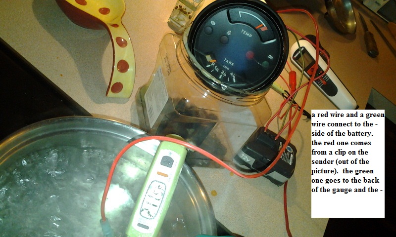 hidden clip... follow the yellow line to the other clip,,,, to the red wire, behind the gauge to the battery. 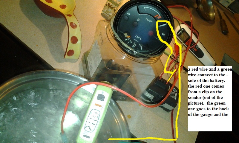 |
|
|
|
| malcolm2 |
Oct 21 2014, 06:10 PM
Post
#30
|
|
Advanced Member Group: Members Posts: 2,745 Joined: 31-May 11 From: Nashville Member No.: 13,139 Region Association: South East States |
Tim, you need an award. (IMG:style_emoticons/default/aktion035.gif) (IMG:style_emoticons/default/aktion035.gif) It worked. I am a good direction follower too.
5 minute video of watching water boil. https://www.youtube.com/watch?v=P1Ld8urUl7c I am not totally out of the woods yet tho. I assumed that this process would shift the range of motion of the needle to include more of the left (cold) half of the gauge while it put the needle in the correct place at 212*F. It looks like it only changed the right half of the range of motion. when it all went back to room temp the needle was pretty much where it was from the start.... about 1/3 up the dial, pointing "thru" the E. making my range from room temp to 212 from the left edge or the E to the middle of the M. Was that what you expected? (IMG:style_emoticons/default/confused24.gif) |
|
|
|
| timothy_nd28 |
Oct 21 2014, 06:36 PM
Post
#31
|
|
Advanced Member Group: Members Posts: 2,299 Joined: 25-September 07 From: IN Member No.: 8,154 Region Association: Upper MidWest |
A couple of things:
You can't measure resistance while everything is powered up. Next, the meter is on the wrong setting. You are on some diode test setting, you should move the selector knob to 2k range when measuring. Do this when power is removed. |
|
|
|
| malcolm2 |
Oct 21 2014, 07:07 PM
Post
#32
|
|
Advanced Member Group: Members Posts: 2,745 Joined: 31-May 11 From: Nashville Member No.: 13,139 Region Association: South East States |
QUOTE(timothy_nd28 @ Oct 21 2014, 07:36 PM) A couple of things: You can't measure resistance while everything is powered up. Next, the meter is on the wrong setting. You are on some diode test setting, you should move the selector knob to 2k range when measuring. Do this when power is removed. OK, I made the correction, did the boil again. set the pot to 0 at boil, moved the pot to adjust the needle to my estimated 212 location checked the ohms from the middle of the pot to the outer terminal: 0.225 on the 2k setting measured free and clear of any power. 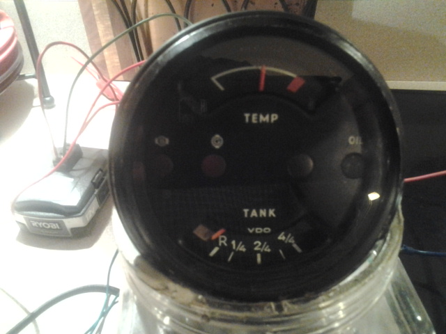 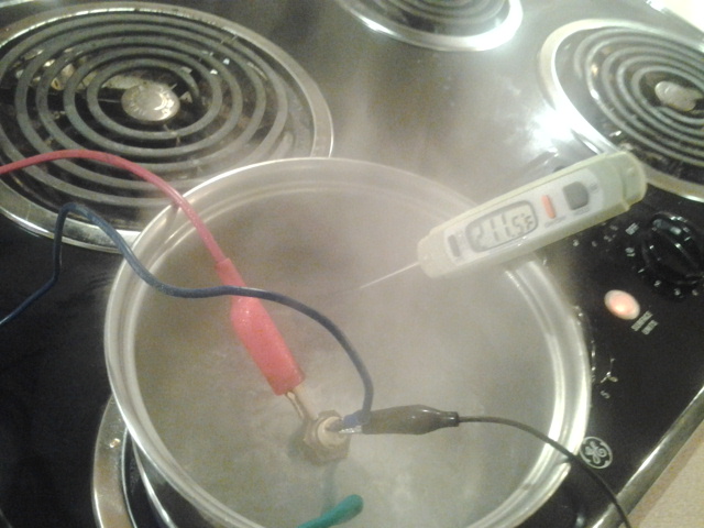 And this is at ROOM TEMP 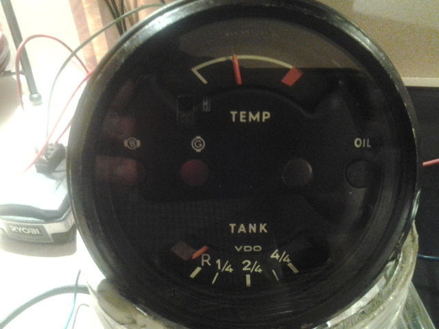 |
|
|
|
| stugray |
Oct 21 2014, 07:08 PM
Post
#33
|
|
Advanced Member Group: Members Posts: 3,824 Joined: 17-September 09 From: Longmont, CO Member No.: 10,819 Region Association: None |
This is about all you ever need on this topic:
http://www.914world.com/bbs2/index.php?showtopic=97987 Thank you McMark. It even explains "the readout of both gauges is exactly the same, and Porsche redesigned the gauge because owners were nervous/cautious/concerned about the normal operating temperature was 'too close' to the red on the early gauges" |
|
|
|
| timothy_nd28 |
Oct 21 2014, 07:15 PM
Post
#34
|
|
Advanced Member Group: Members Posts: 2,299 Joined: 25-September 07 From: IN Member No.: 8,154 Region Association: Upper MidWest |
what is the resistance of the sensor when at room temperature?
|
|
|
|
| malcolm2 |
Oct 21 2014, 07:18 PM
Post
#35
|
|
Advanced Member Group: Members Posts: 2,745 Joined: 31-May 11 From: Nashville Member No.: 13,139 Region Association: South East States |
QUOTE(stugray @ Oct 21 2014, 08:08 PM) This is about all you ever need on this topic: http://www.914world.com/bbs2/index.php?showtopic=97987 Thank you McMark. It even explains "the readout of both gauges is exactly the same, and Porsche redesigned the gauge because owners were nervous/cautious/concerned about the normal operating temperature was 'too close' to the red on the early gauges" That is a good post, but it does not deal with my issue. the left most point of the red mark represents 156.7*C or 314*F. In boiling water, my needle is on what seems to be 300*F, just a short distance from that edge of the red mark. the actual temp of the sensor when in boiling water is 100* C or 212*F. I estimate that to be just past 1/2 way thru the range of the whole gauge: from the left white tick to the leading edge of the red. |
|
|
|
| malcolm2 |
Oct 21 2014, 07:26 PM
Post
#36
|
|
Advanced Member Group: Members Posts: 2,745 Joined: 31-May 11 From: Nashville Member No.: 13,139 Region Association: South East States |
QUOTE(timothy_nd28 @ Oct 21 2014, 08:15 PM) what is the resistance of the sensor when at room temperature? I made those measurements last night.... at about 85*F and the meter is on 2K. One probe is on the terminal and the other is on the brass nut of the sensor. I got a reading of 1.800. I just verified that number. |
|
|
|
| timothy_nd28 |
Oct 21 2014, 07:51 PM
Post
#37
|
|
Advanced Member Group: Members Posts: 2,299 Joined: 25-September 07 From: IN Member No.: 8,154 Region Association: Upper MidWest |
Sorry, was unaware that the needle was not traveling to the cold mark, thought we resolved this earlier by grounding the sensor's casing. I think your sensor maybe out of tolerance. Let's try bench testing once again, the same way but not with the boiling water this time.
Adjust your potentiometer to 1000 ohms, instead of 0. You should now have a total resistance of 2800 ohms at room temperature (measuring from the sensors' case to the G terminal on the back of the gauge). Power it up and see if the needle moved any closer to the cold position. |
|
|
|
| malcolm2 |
Oct 21 2014, 08:10 PM
Post
#38
|
|
Advanced Member Group: Members Posts: 2,745 Joined: 31-May 11 From: Nashville Member No.: 13,139 Region Association: South East States |
QUOTE(timothy_nd28 @ Oct 21 2014, 08:51 PM) Sorry, was unaware that the needle was not traveling to the cold mark, thought we resolved this earlier by grounding the sensor's casing. I think your sensor maybe out of tolerance. Let's try bench testing once again, the same way but not with the boiling water this time. Adjust your potentiometer to 1000 ohms, instead of 0. You should now have a total resistance of 2800 ohms at room temperature (measuring from the sensors' case to the G terminal on the back of the gauge). Power it up and see if the needle moved any closer to the cold position. it is actually about 3 mm closer to the left WITHOUT the pot in the circuit. I tried it in line then took the pot out, re-connected and it dropped (moved left) a smidge when re-connected. update: measuring from the sensors case to the G term with the pot in line and the meter on 2K I get .242. 2nd update: I made a circuit from the terminal of the sensor thru the pot (at 1000 ohms) and checked it at room temp. meter on 20K setting, I read 3.2.... remove the pot and I read 2.2. Seems logical. |
|
|
|
| stugray |
Oct 22 2014, 12:11 AM
Post
#39
|
|
Advanced Member Group: Members Posts: 3,824 Joined: 17-September 09 From: Longmont, CO Member No.: 10,819 Region Association: None |
QUOTE(timothy_nd28 @ Oct 21 2014, 07:15 PM) what is the resistance of the sensor when at room temperature? I believe that the sensor is a type 2252 thermistor. 2250 Ohms at 25 C (77F) 153 ohms at 100C (212F) 42 ohms at 150C (300F) So I am not quite grasping what inserting a series resistor in the circuit will do. When the oil reaches temp ~240 F = 115C = sensor is 100 ohms. If you put a 1000 ohm series resistor in line, then when the sensor is at 240F it will be 100 Ohms and the gauge will see 1100 Ohms which it will think is 42C (107F). So all the series resistor can do is decrease resolution? (IMG:style_emoticons/default/confused24.gif) I think I will break out my spare parts as well. I have to figure out how this works to tap my datalogger into the temp sensor anyway. |
|
|
|
| malcolm2 |
Oct 22 2014, 11:54 AM
Post
#40
|
|
Advanced Member Group: Members Posts: 2,745 Joined: 31-May 11 From: Nashville Member No.: 13,139 Region Association: South East States |
QUOTE(stugray @ Oct 22 2014, 01:11 AM) So I am not quite grasping what inserting a series resistor in the circuit will do. When the oil reaches temp ~240 F = 115C = sensor is 100 ohms. If you put a 1000 ohm series resistor in line, then when the sensor is at 240F it will be 100 Ohms and the gauge will see 1100 Ohms which it will think is 42C (107F). So all the series resistor can do is decrease resolution? (IMG:style_emoticons/default/confused24.gif) Tim was trying to make the gauge go to the right place at a known temperature. It seems that the sensor is doing what it is supposed to, but the gauge is off. So I assume we were faking out the gauge pumping some additional ohms into the system to move the needle to 100*C. It worked. I got the gauge to where I estimated 100*C was. It just did not completely fix my gauge. This post is on hold for a while. I am getting extra help from Tim on this. He has a theory or two he is going to try..... more to come. (IMG:style_emoticons/default/popcorn[1].gif) |
|
|
|
|
1 User(s) are reading this topic (1 Guests and 0 Anonymous Users)
0 Members:

|
Lo-Fi Version | Time is now: 5th May 2024 - 06:01 AM |
Invision Power Board
v9.1.4 © 2024 IPS, Inc.