|
|
|
Porsche, and the Porsche crest are registered trademarks of Dr. Ing. h.c. F. Porsche AG.
This site is not affiliated with Porsche in any way. Its only purpose is to provide an online forum for car enthusiasts. All other trademarks are property of their respective owners. |
|
|

  |

| OU8AVW |
 Oct 28 2014, 07:19 AM Oct 28 2014, 07:19 AM
Post
#1
|
|
Yacht Rigger  Group: Members Posts: 1,803 Joined: 1-October 08 From: Granbury, TX Member No.: 9,601 Region Association: Southwest Region |
I am hooking up all the D-Jet components and i have a few questions. My motor is a 2.0 out of a 1975 car built to a 2056 with a Raby FI cam. I'm using all stock FI.
I might have forgotten something. I have my head temp sender but I'm not sure how it connects. Tin is installed so I see that is goes into the hole next to the #3 intake but does it screw into the head somewhere? Do i have to pull the tin off to install it? (IMG:style_emoticons/default/dry.gif) Next: I see on my harness a plug for the air flow meter but my car came with a stupid aftermarket air cleaner. Where shiuld the AFM be? Is it attached to the stock air cleaner like my bus and 944 or is it a separate thing attached next to the battery tray? One more: My heads have two breather holes each adjacent to the intakes. I am told I should block these off. Anyone know what thread they are? When I got the car they were blocked with bronze pipe fittings. Should I make one of these a proper breather? Thanks! |
   |

 
|
| pilothyer |
Oct 28 2014, 07:55 AM
Post
#2
|
|
Member Group: Members Posts: 838 Joined: 21-May 08 From: N. Alabama Member No.: 9,080 Region Association: South East States |
As for the head temp sensor it is attached to the cylinder head between cylinder 3 and 4 but closer to cylinder 3, access is gained through the hole in the engine tin on that side. If you look in there and see a boss but no threaded hole, the heads may have been switched or two left bank heads were used.
|
|
|
|
| type47 |
Oct 28 2014, 07:56 AM
Post
#3
|
|
Viermeister Group: Members Posts: 4,254 Joined: 7-August 03 From: Vienna, VA Member No.: 994 Region Association: MidAtlantic Region |
QUOTE(OU8AVW @ Oct 28 2014, 05:19 AM)  I have my head temp sender but I'm not sure how it connects. cylinder head temperature sensor is a 14mm ring that is installed under the spark plug unless you're talking about the FI sensor, my bad. Sensor for FI, not cylinder head temp gauge, is in a threaded hole on the head; somewhat awkward to get to. I see on my harness a plug for the air flow meter but my car came with a stupid aftermarket air cleaner. Where should the AFM be? Is it attached to the stock air cleaner like my bus and 944 or is it a separate thing attached next to the battery tray? hmmm, this makes me think you have L-Jet not D-Jet. L-Jet has an air flow meter, D-Jet has a Manifold Pressure Sensor. There was a L-Jet 1.8 in '75 My heads have two breather holes each adjacent to the intakes. head breather tubes are connected to an anti-flashback valve (3 way "valve") then to the air cleaner housing But on the other hand, these holes could be holes for the emission equipment. The have to be plugged if you remove the emission stuff. I've heard that you can use an old valve adjust screw to close it up. |
|
|
|
| bdstone914 |
Oct 28 2014, 08:00 AM
Post
#4
|
|
bdstone914 Group: Members Posts: 4,508 Joined: 8-November 03 From: Riverside CA Member No.: 1,319 |
D jet does not use an air flow meter. Show the plug and we can tell you what it connects to. The vents in the heads are non threaded 13mm tubes. They should be connected to the anti flash valve that goes into the stock air cleaner. I have 2.0 air cleaners if you want the correct hookups.
Bruce |
|
|
|
| bdstone914 |
Oct 28 2014, 08:01 AM
Post
#5
|
|
bdstone914 Group: Members Posts: 4,508 Joined: 8-November 03 From: Riverside CA Member No.: 1,319 |
Duplicate post
|
|
|
|
| OU8AVW |
Oct 28 2014, 08:27 AM
Post
#6
|
|
Yacht Rigger Group: Members Posts: 1,803 Joined: 1-October 08 From: Granbury, TX Member No.: 9,601 Region Association: Southwest Region |
D-Jet = no air flow meter. That answers that.
I'll root around more for the temp sending hole. Sounds like I need to pull the tin. Bummer. You guys make a good point about switching the heads. I thought I paid attention to this. I'll have a look. I'll take a picture of my heads and get more input on the mystery holes. Thanks! |
|
|
|
| r_towle |
Oct 28 2014, 06:15 PM
Post
#7
|
|
Custom Member Group: Members Posts: 24,560 Joined: 9-January 03 From: Taxachusetts Member No.: 124 Region Association: North East States |
Hopefully you don't need to swap the heads around..
|
|
|
|
| Bleyseng |
Oct 28 2014, 08:09 PM
Post
#8
|
|
Aircooled Baby! Group: Members Posts: 13,034 Joined: 27-December 02 From: Seattle, Washington (for now) Member No.: 24 Region Association: Pacific Northwest |
Are these stock 75 heads? Then those holes are for the EGR plumbing and Air pump. Block em off with valve adjusting screws
|
|
|
|
| OU8AVW |
Oct 30 2014, 05:08 PM
Post
#9
|
|
Yacht Rigger Group: Members Posts: 1,803 Joined: 1-October 08 From: Granbury, TX Member No.: 9,601 Region Association: Southwest Region |
QUOTE(Bleyseng @ Oct 28 2014, 07:09 PM) Are these stock 75 heads? Then those holes are for the EGR plumbing and Air pump. Block em off with valve adjusting screws 75, yes. But they are bigger than valve adjuster screws.... |
|
|
|
| Dave_Darling |
Oct 30 2014, 05:26 PM
Post
#10
|
|
914 Idiot Group: Members Posts: 14,980 Joined: 9-January 03 From: Silicon Valley / Kailua-Kona Member No.: 121 Region Association: Northern California |
Post pictures of the mystery connector and the holes.
--DD |
|
|
|
| OU8AVW |
Oct 31 2014, 12:06 PM
Post
#11
|
|
Yacht Rigger Group: Members Posts: 1,803 Joined: 1-October 08 From: Granbury, TX Member No.: 9,601 Region Association: Southwest Region |
QUOTE(Dave_Darling @ Oct 30 2014, 04:26 PM) Post pictures of the mystery connector and the holes. --DD  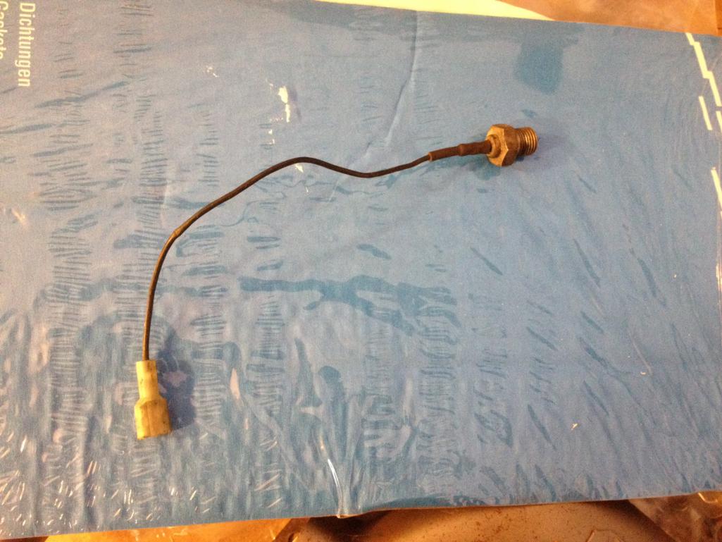 |
|
|
|
| OU8AVW |
Oct 31 2014, 12:10 PM
Post
#12
|
|
Yacht Rigger Group: Members Posts: 1,803 Joined: 1-October 08 From: Granbury, TX Member No.: 9,601 Region Association: Southwest Region |
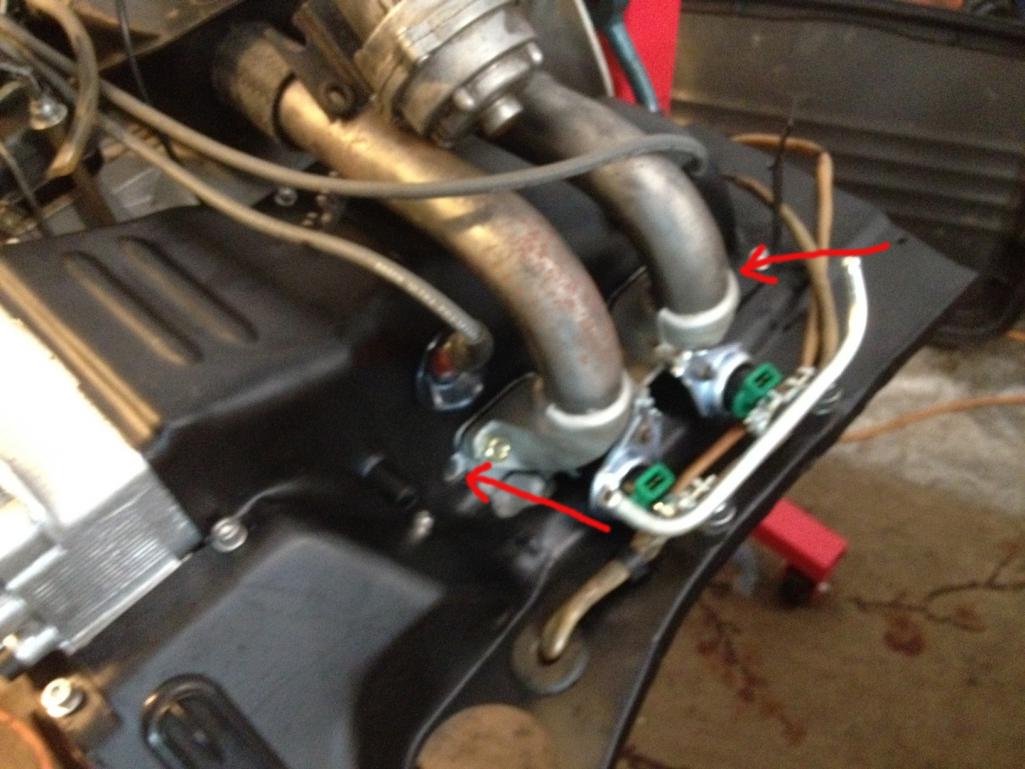 These things are on both heads and both sides of the air intake. They were plugged with household pipe fittings. |
|
|
|
| ChrisFoley |
Oct 31 2014, 12:13 PM
Post
#13
|
|
I am Tangerine Racing Group: Members Posts: 7,907 Joined: 29-January 03 From: Bolton, CT Member No.: 209 Region Association: None |
The hole for that CHT sender is normally found on the passenger side cylinder head.
The access hole in the tin is obscured by the #3 intake runner. There is supposed to be a grommet in the tin to support the wire and prevent too much cooling air from escaping. With the intake off you may be able to install the sender without removing the tin. |
|
|
|
| ChrisFoley |
Oct 31 2014, 12:16 PM
Post
#14
|
|
I am Tangerine Racing Group: Members Posts: 7,907 Joined: 29-January 03 From: Bolton, CT Member No.: 209 Region Association: None |
The arrowed holes are from the air-pump (emission control) fittings to the exhaust ports.
The larger valve adjusters have the correct thread unless a PO re-tapped the holes for a different type fitting. As long as they're plugged leave 'em alone. |
|
|
|
| OU8AVW |
Nov 1 2014, 10:43 AM
Post
#15
|
|
Yacht Rigger Group: Members Posts: 1,803 Joined: 1-October 08 From: Granbury, TX Member No.: 9,601 Region Association: Southwest Region |
So, heads are bass akwards. What's the penalty for leaving them and pulling head temp off of #1? Any other issues?
|
|
|
|
| ClayPerrine |
Nov 1 2014, 10:55 AM
Post
#16
|
|
Life's been good to me so far..... Group: Admin Posts: 15,392 Joined: 11-September 03 From: Hurst, TX. Member No.: 1,143 Region Association: NineFourteenerVille |
QUOTE(OU8AVW @ Nov 1 2014, 11:43 AM) So, heads are bass akwards. What's the penalty for leaving them and pulling head temp off of #1? Any other issues? The #3 cylinder is farthest from the cooling fan, so it runs hotter than all the others. You need to put the sensor in the correct location so it receives the correct temp. Otherwise it will run too rich. IIRC, the sensor is a 10 x 1.0 thread, so just pull the right hand tin to drill and tap the head. The boss is cast in the head, and you don't have to drill it deep. |
|
|
|
| OU8AVW |
Nov 1 2014, 01:36 PM
Post
#17
|
|
Yacht Rigger Group: Members Posts: 1,803 Joined: 1-October 08 From: Granbury, TX Member No.: 9,601 Region Association: Southwest Region |
QUOTE(ClayPerrine @ Nov 1 2014, 09:55 AM) QUOTE(OU8AVW @ Nov 1 2014, 11:43 AM) So, heads are bass akwards. What's the penalty for leaving them and pulling head temp off of #1? Any other issues? The #3 cylinder is farthest from the cooling fan, so it runs hotter than all the others. You need to put the sensor in the correct location so it receives the correct temp. Otherwise it will run too rich. IIRC, the sensor is a 10 x 1.0 thread, so just pull the right hand tin to drill and tap the head. The boss is cast in the head, and you don't have to drill it deep. Cool.... |
|
|
|
|
1 User(s) are reading this topic (1 Guests and 0 Anonymous Users)
0 Members:

|
Lo-Fi Version | Time is now: 18th April 2024 - 10:55 PM |
Invision Power Board
v9.1.4 © 2024 IPS, Inc.