|
|
|
Porsche, and the Porsche crest are registered trademarks of Dr. Ing. h.c. F. Porsche AG.
This site is not affiliated with Porsche in any way. Its only purpose is to provide an online forum for car enthusiasts. All other trademarks are property of their respective owners. |
|
|

  |

| raynekat |
 Nov 13 2016, 09:46 PM Nov 13 2016, 09:46 PM
Post
#121
|
|
Advanced Member  Group: Members Posts: 2,171 Joined: 30-December 14 From: Coeur d'Alene, Idaho Member No.: 18,263 Region Association: Pacific Northwest |
Getting the fan "dialed in" a bit more....
Newly plated strap with new foil decal (which is NOS and has the wrong displacement on it...who knew?....and inconsequential in the end). The displacement on the foil decal for the 1973 engine is a 2.2 which is obviously wrong; should be 2.4-ish. 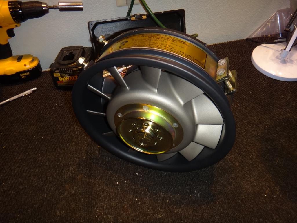 |
   |

 
|
| raynekat |
Nov 13 2016, 09:47 PM
Post
#122
|
|
Advanced Member Group: Members Posts: 2,171 Joined: 30-December 14 From: Coeur d'Alene, Idaho Member No.: 18,263 Region Association: Pacific Northwest |
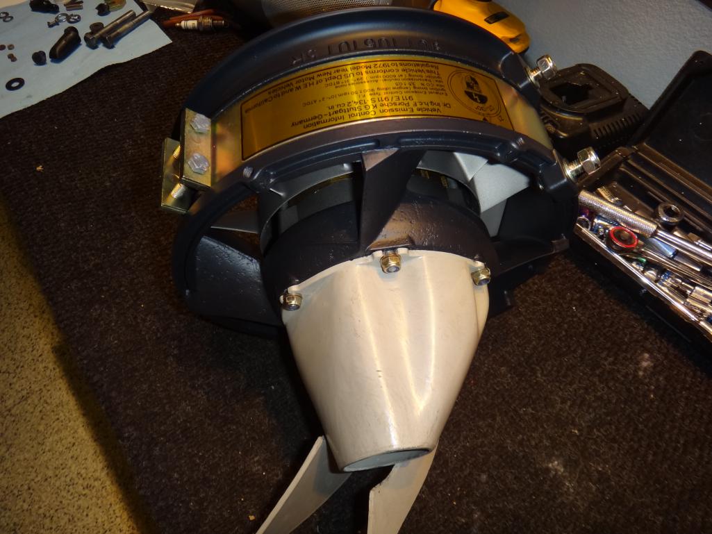
Can see the displacement error better on this pic...
 |
|
|
|
| raynekat |
Nov 13 2016, 09:52 PM
Post
#123
|
|
Advanced Member Group: Members Posts: 2,171 Joined: 30-December 14 From: Coeur d'Alene, Idaho Member No.: 18,263 Region Association: Pacific Northwest |
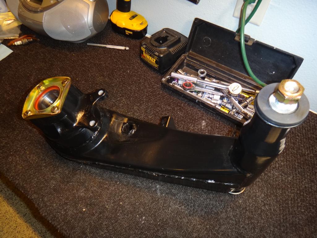
New struts arrived from Elephant Racing.
My 2nd hand Bilstein units had worn out spindles so were no good. Ended up ordering RSR struts that had the raised spindle, but put HD Bilstein dampers in them so they aren't too stiff for the street. Also came with their adjustable bump steer kit & brake line supports (necessary due to the coil over capability of the struts, which I won't be utilizing). 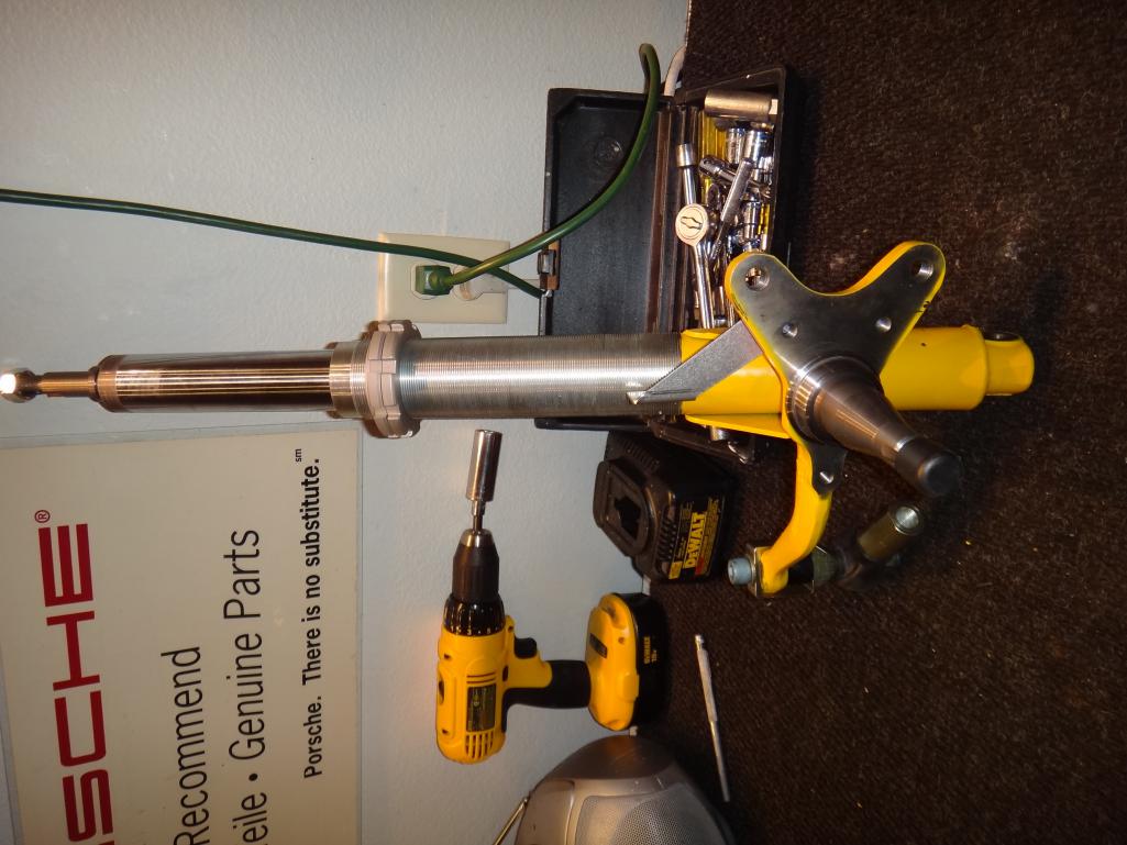 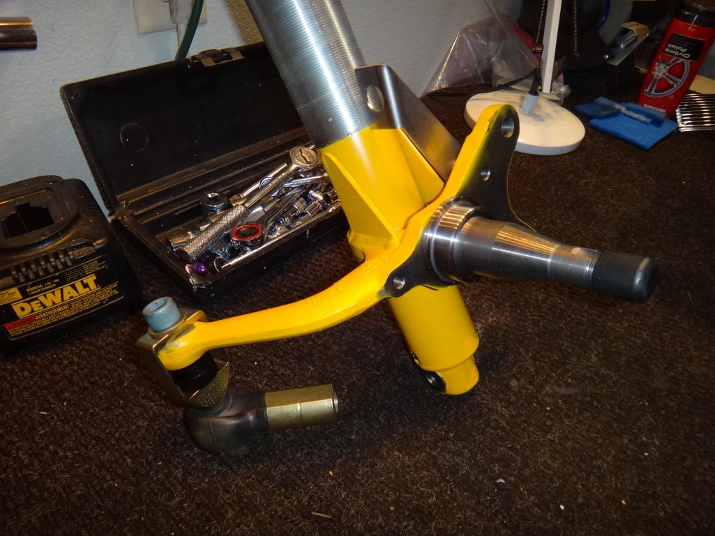 |
|
|
|
| raynekat |
Nov 13 2016, 09:54 PM
Post
#124
|
|
Advanced Member Group: Members Posts: 2,171 Joined: 30-December 14 From: Coeur d'Alene, Idaho Member No.: 18,263 Region Association: Pacific Northwest |
New rubber bushings (from Elephant Racing) and factory bearings for the rear.
 |
|
|
|
| raynekat |
Nov 13 2016, 09:55 PM
Post
#125
|
|
Advanced Member Group: Members Posts: 2,171 Joined: 30-December 14 From: Coeur d'Alene, Idaho Member No.: 18,263 Region Association: Pacific Northwest |
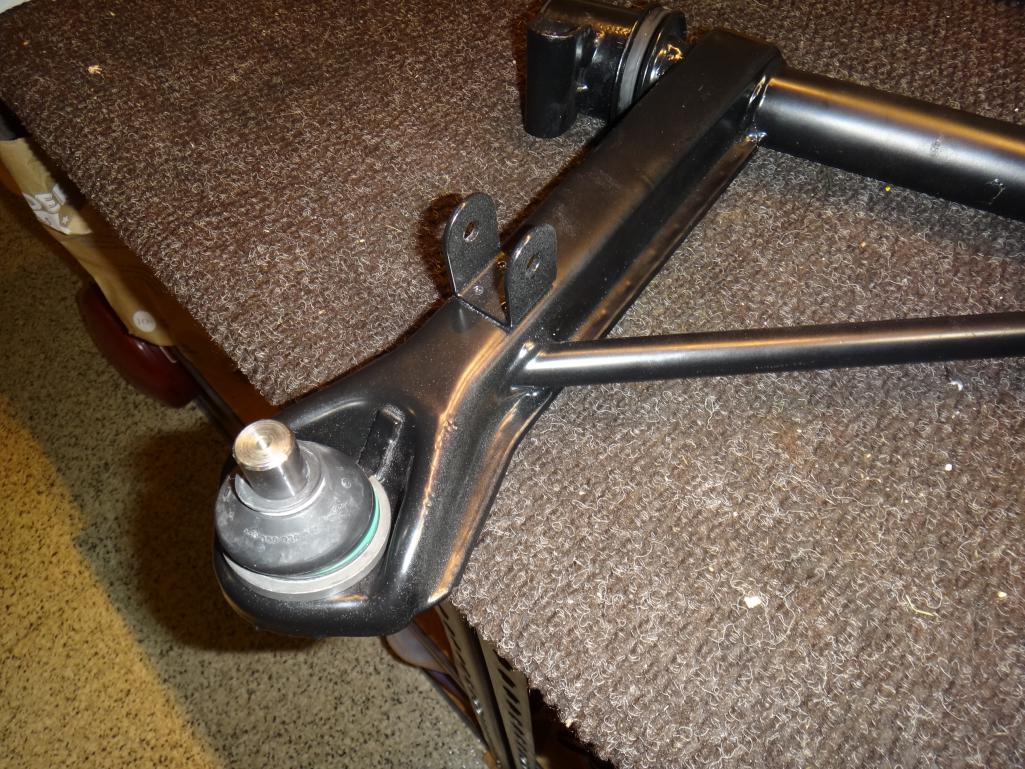
New Lemforder ball joints and Elephant Racing rubber bushings for the front A-arms as well.
 |
|
|
|
| cary |
Nov 14 2016, 12:15 AM
Post
#126
|
|
Advanced Member Group: Members Posts: 3,900 Joined: 26-January 04 From: Sherwood Oregon Member No.: 1,608 Region Association: Pacific Northwest |
Ran back to Forest Grove after church .......................
Here's the shot of the weld in of the right taillight panel to qtr. panel I forgot yesterday. Funny thing. I started today with doing the left side. But once again forgot to shoot a picture of it. 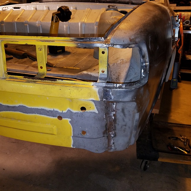 I let Super In Law take the welder to build up the matching left side inner fender corner. So I went back to re engineering the removable exhaust shield. I crawled under Mark's project car. The standoffs are right up to the taillight panel. I'm going to move Doug's forward about a 1/4" forward. I'm thinking we should hold off on getting the exhaust shield ceramic coated until we install the engine at Rothsport. The mounting holes might need to be changed to accommodate the 911 exhaust. Thoughts ? 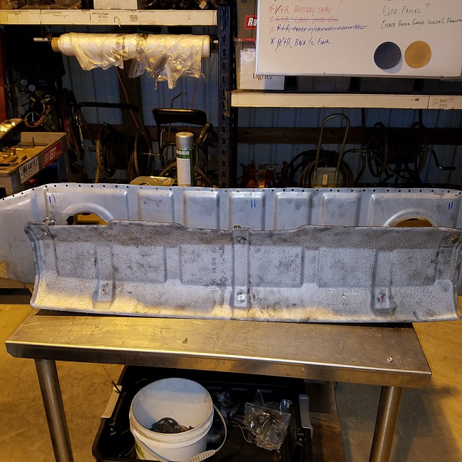 Here's a shot of the shield attached to the trunk panel. It's attached with self tapping screws. Test fit was a beautiful thing. (IMG:style_emoticons/default/biggrin.gif) 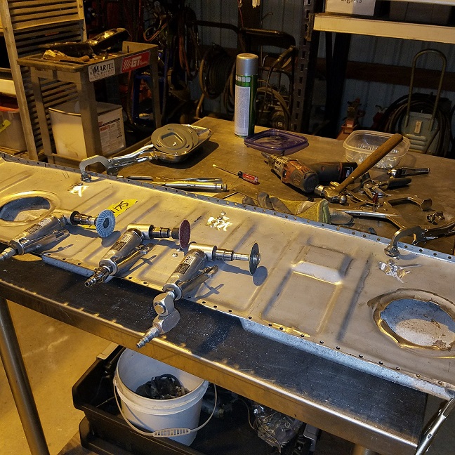 Plan is to run back out to Forest Grove on Tuesday night to weld in the inner corner and trunk panel. (IMG:style_emoticons/default/welder.gif) Then it was time to fiddle with Super In Laws corner piece. 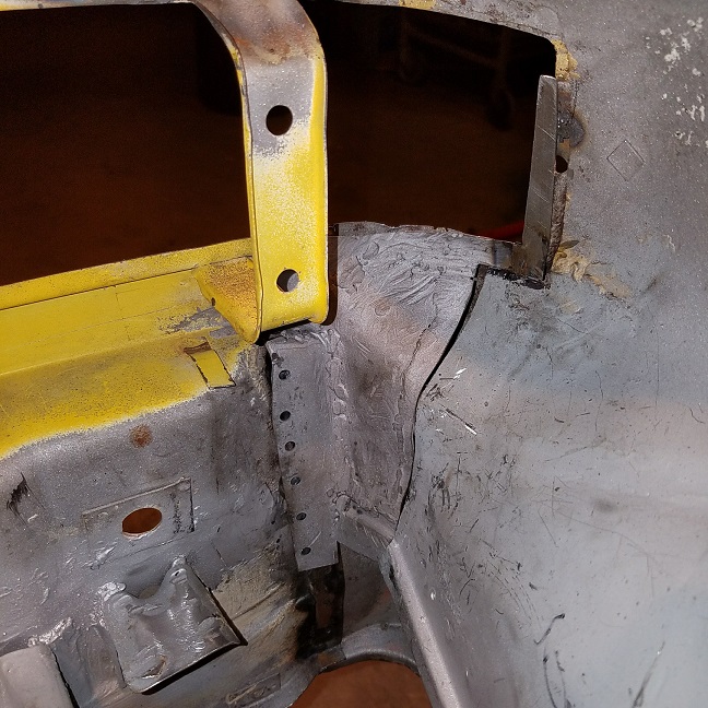 |
|
|
|
| cary |
Nov 16 2016, 09:31 AM
Post
#127
|
|
Advanced Member Group: Members Posts: 3,900 Joined: 26-January 04 From: Sherwood Oregon Member No.: 1,608 Region Association: Pacific Northwest |
Decided a little moonlighting was in order to get the taillight/trunk all finished up.
I was hoping to get it wrapped up. Almost, but not quite.  Finished up the back of the right corner. 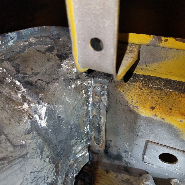 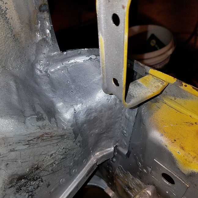 Then on to the left corner. Started with the vertical portion of the taillight hole. Then the horizontal. Then out to the front and the last three rosettes on the face of the taillight panel. Forgot to shoot a picture, Ill get it on Thursday. Then on to the holes punched on the backside tying all three layers together. Then last but not least the down butt weld tying it back into the inner fender. It looks a little bumpy in the left area. That left over brazing from the factory or the attempted previous repair. 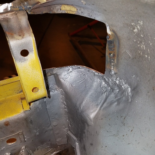 After that was finished I moved on to finishing up the removal exhaust shield. In the background Super In Law was working on installing the new parts washer motor. I'll finish up this post after my day job ........... LOL |
|
|
|
| cary |
Nov 16 2016, 09:42 PM
Post
#128
|
|
Advanced Member Group: Members Posts: 3,900 Joined: 26-January 04 From: Sherwood Oregon Member No.: 1,608 Region Association: Pacific Northwest |
After welding the shield stand offs to the bottom of the trunk panel I rounded the corners to make them a little more user friendly.
Before : 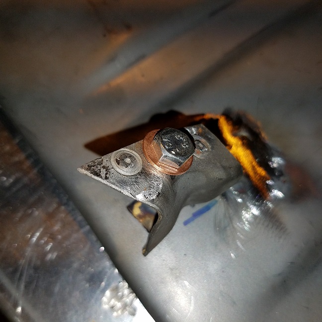 After : 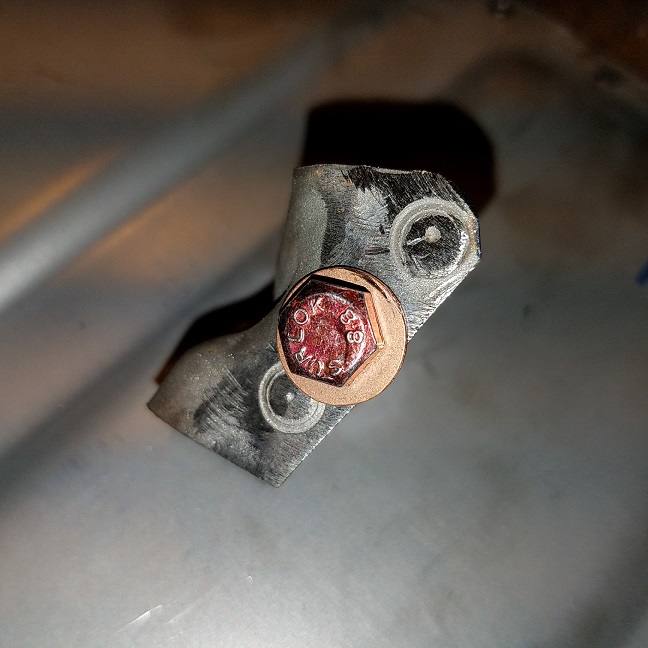 Then gave the trunk panel another test fit only to find its a smidgen too tight in the new back left corner. So I didn't get it finished up last night. (IMG:style_emoticons/default/welder.gif) So it will get a little nip and tuck in the am. 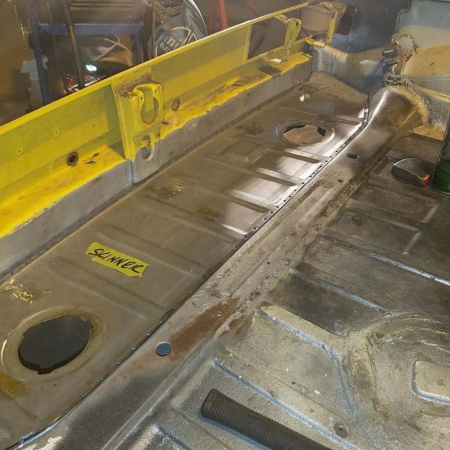 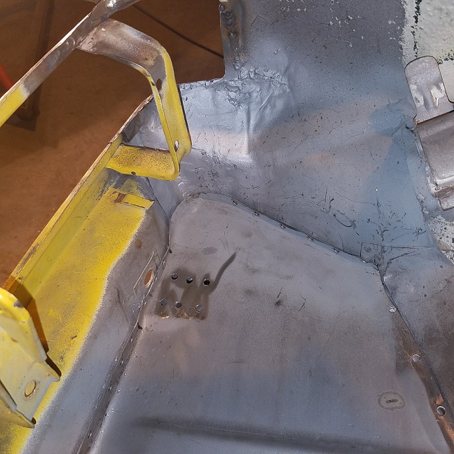 |
|
|
|
| cary |
Nov 17 2016, 09:01 PM
Post
#129
|
|
Advanced Member Group: Members Posts: 3,900 Joined: 26-January 04 From: Sherwood Oregon Member No.: 1,608 Region Association: Pacific Northwest |
Got off to a late start, but finally got back to welding in the trunk.
First issue was doing the little cut and tuck on each corner. It didn't take too much. Then on to aligning the trunk panel to the taillight panel. I'm primarily using the factory spot weld dimples as the guide. Used a combination of Vise Grips and self taping screws to hold it in place. I have a 5th 18" Vise Grip ( R model) that I use to clamp right next to the rosette that I'm welding. 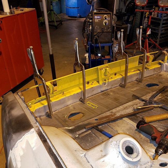 To get the nice flat fit I'm only welding the taillight panel portion between the braces. Slow process. Hammer it tight. Clamp down the Vise Grip. Hammer it flat again. Then weld. Then start the process again on the other end. 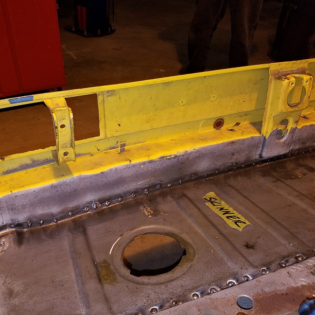 Then on to the other side, the rosettes on the transmission mount support. I used self taping screws in every third hole to tighten it down. Once again I only welded in the center section .. 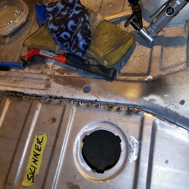 I started stitch welding in the tranny mount to trunk panel butt weld seam. It's going to be a little touchy. Nice solid new metal with the trunk panel. Old thinner metal in the tranny mount. (IMG:style_emoticons/default/sad.gif) 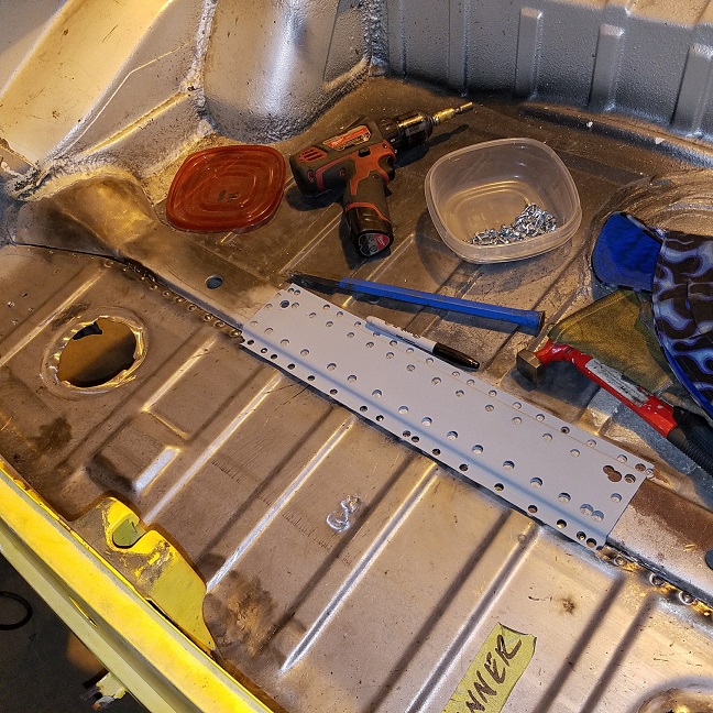 |
|
|
|
| jmz |
Nov 18 2016, 11:23 AM
Post
#130
|
|
Member Group: Members Posts: 174 Joined: 11-April 16 From: Lone Star State Member No.: 19,886 Region Association: None |
wondering just how much scope creep to expect here. Looks like a nice build!
|
|
|
|
| raynekat |
Nov 18 2016, 01:39 PM
Post
#131
|
|
Advanced Member Group: Members Posts: 2,171 Joined: 30-December 14 From: Coeur d'Alene, Idaho Member No.: 18,263 Region Association: Pacific Northwest |
QUOTE(jmz @ Nov 18 2016, 09:23 AM)  wondering just how much scope creep to expect here. Looks like a nice build! We know the rear floor boards in the cabin and the lower windshield surround needs work plus some little stuff. When Cary gets the entire chassis sandblasted and up on the rotisserie here in the coming weeks, we'll have a better idea what needs to be further addressed metal-wise. |
|
|
|
| cary |
Nov 19 2016, 12:33 AM
Post
#132
|
|
Advanced Member Group: Members Posts: 3,900 Joined: 26-January 04 From: Sherwood Oregon Member No.: 1,608 Region Association: Pacific Northwest |
Started the day with finishing the butt weld on the humped portions of the tranny support. Then moved on to the trunk reinforcement plate. Weld Thru Primer. Then used about 40 self tapping screws to hold it down tight. Doug had offered to buy a new one and I turned it down. I should have taken him up on it. The problem with reusing the old one is the your welding right into the spot weld cutter hole. Which is thinned down and I blew right thru about a half dozen of them. (IMG:style_emoticons/default/sad.gif) On top of that the holes are too big, which creates a huge rosette.
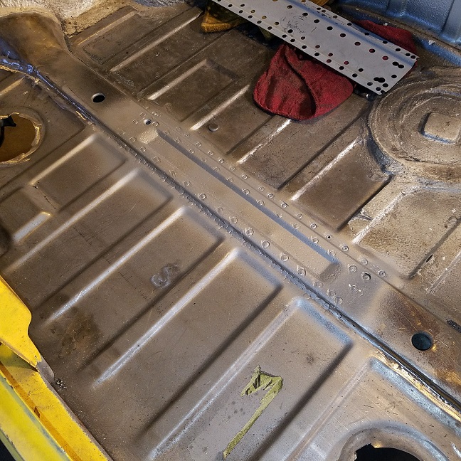 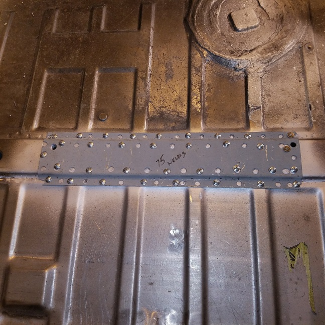 Now that the center section is welded in nice and tight I set about welding in the sides. I try to replicate the way the part was originally installed. Spot welds on the sides and tack welds in the back corner. Then only lightly grind down the welds because they get smothered in seam sealer. 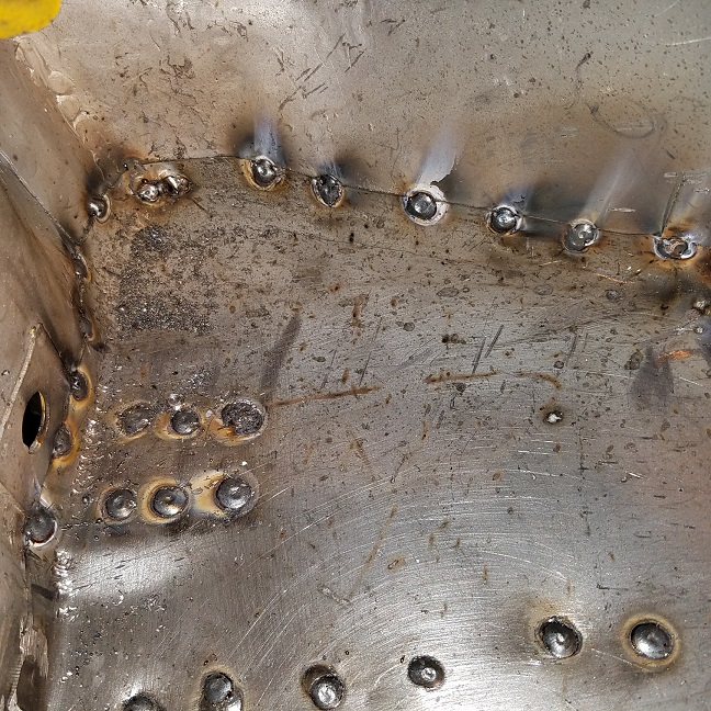 Then the final step. Weld back on the upper corner braces. 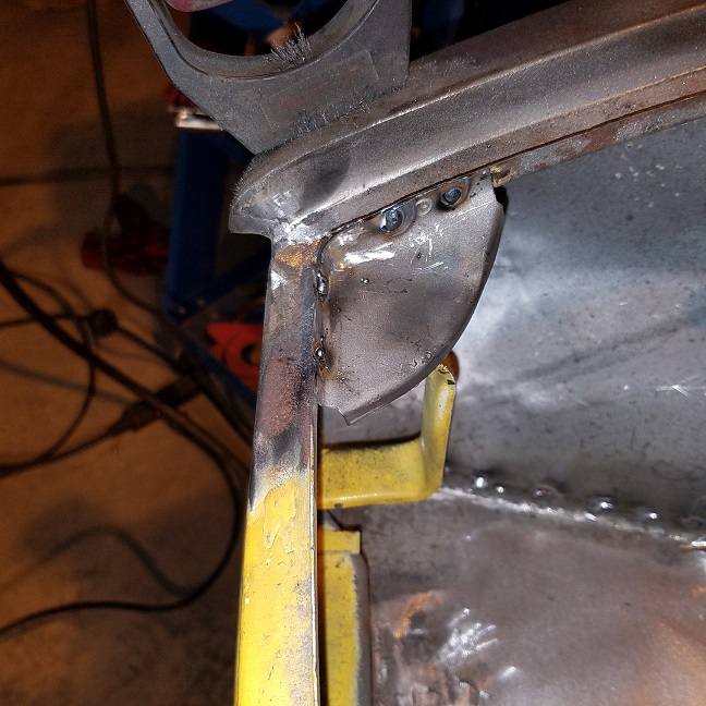 After our initial set back after finding the wrinkled qtr. panels. The back end is finally getting wrapped up. 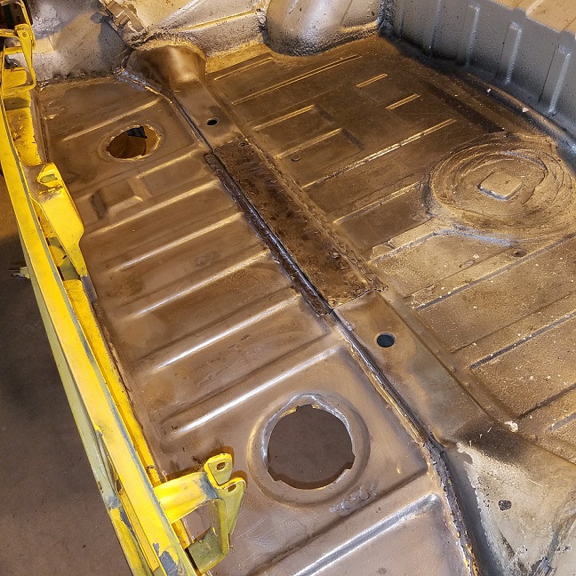 Gave the new metal a light coating of SE primer to protect it. 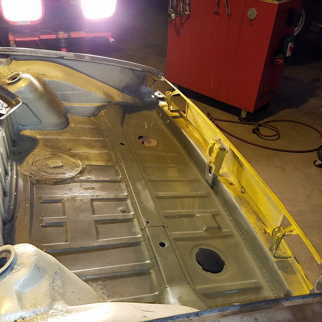 End of a great day .................. Tomorrow onto cutting the oil tank holes. 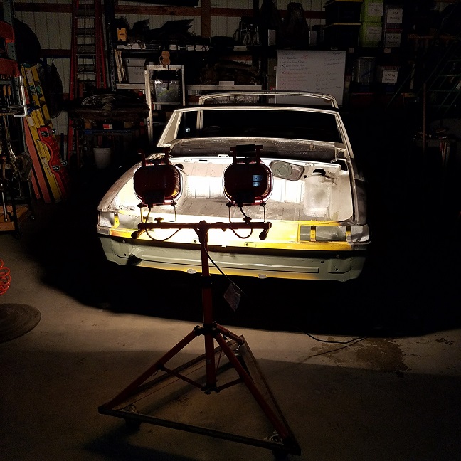 |
|
|
|
| mepstein |
Nov 19 2016, 05:49 AM
Post
#133
|
|
914-6 GT in waiting Group: Members Posts: 20,819 Joined: 19-September 09 From: Landenberg, PA/Wilmington, DE Member No.: 10,825 Region Association: MidAtlantic Region |
QUOTE(raynekat @ Nov 13 2016, 10:46 PM) Getting the fan "dialed in" a bit more.... Newly plated strap with new foil decal (which is NOS and has the wrong displacement on it...who knew?....and inconsequential in the end). The displacement on the foil decal for the 1973 engine is a 2.2 which is obviously wrong; should be 2.4-ish. The downside with our cars is the pretty parts are hidden compared to a 911. Nice job though putting together the pieces. |
 |
|
| raynekat |
Nov 19 2016, 04:51 PM
Post
#134
|
|
Advanced Member Group: Members Posts: 2,171 Joined: 30-December 14 From: Coeur d'Alene, Idaho Member No.: 18,263 Region Association: Pacific Northwest |
QUOTE(mepstein @ Nov 19 2016, 03:49 AM) The downside with our cars is the pretty parts are hidden compared to a 911. Nice job though putting together the pieces. So true. But I'll know it looks the way I want it. Also if this engine comes out and goes into a 911/912, it will be good to go. |
|
|
|
| cary |
Nov 20 2016, 08:27 PM
Post
#135
|
|
Advanced Member Group: Members Posts: 3,900 Joined: 26-January 04 From: Sherwood Oregon Member No.: 1,608 Region Association: Pacific Northwest |
Sorry I'm a little late. Had to do a little malware work on this PC. (IMG:style_emoticons/default/evilgrin.gif)
On to to cutting the holes for the oil tank in the left fender/engine compartment. Here's a little write up from Wayne at Pelican. The installation of the oil tank requires you to drill seven holes in the side of your engine compartment. Fortunately, all 914s have indentations in their sheet metal where the holes are to be drilled. If you look on the side of the wall inside your 914, they are located just above and below your relay box. You probably never noticed them before - I know I never did. The holes that must be drilled require a set of hole saws: 4" to 4.5" for the oil filter 2" for the breather hoses 2.5" for the filler neck 1.5" for the 2 hole return line holes. A shot from the 914 PET. 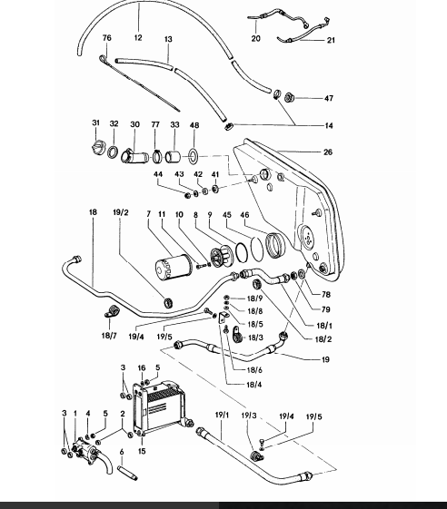 I already had the hole template that Doug had drawn up in my possession. Then Doug brought out the oil tank itself. So I was ready for battle. 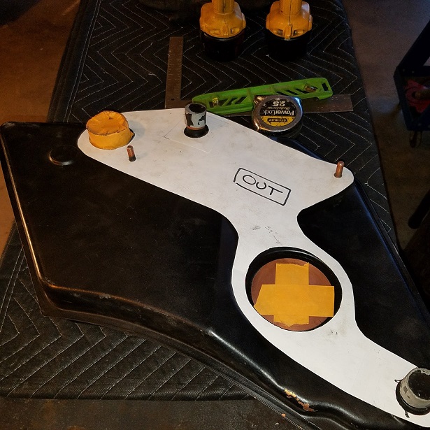 But we didn't have any hole saws that large. So off to ACE I went. The problem is, I bought the first couple hole saws too small. I should have pulled the Pelican info up onto the 55" computer monitor. (IMG:style_emoticons/default/sad.gif) So I might need to do some artwork with the carbide burr cutter. But I'm hoping if one uses a very soft and slow touch I should be able to enlarge the holes with the correct hole saw. I just returned from Lowes with the correct ones. 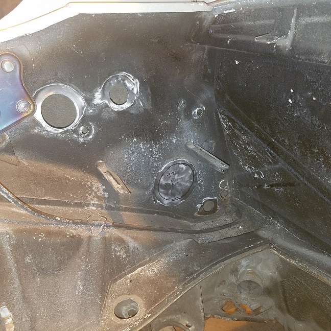 |
|
|
|
| raynekat |
Nov 20 2016, 08:53 PM
Post
#136
|
|
Advanced Member Group: Members Posts: 2,171 Joined: 30-December 14 From: Coeur d'Alene, Idaho Member No.: 18,263 Region Association: Pacific Northwest |
Don't drill that oil filter opening 4-4.5" !!!! Be careful with that Axe Eugene. (IMG:style_emoticons/default/smile.gif)
That's too big; Wayne is wrong on that one. I measured the big rubber gasket that goes in there and it's more like 3.8-3.9". |
|
|
|
| cary |
Nov 20 2016, 10:18 PM
Post
#137
|
|
Advanced Member Group: Members Posts: 3,900 Joined: 26-January 04 From: Sherwood Oregon Member No.: 1,608 Region Association: Pacific Northwest |
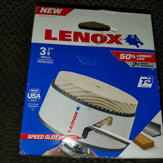
I bought a 4". That's what everyone stocks. I just ordered a 3 7/8 from Amazon.
|
|
|
|
| cary |
Nov 20 2016, 11:00 PM
Post
#138
|
|
Advanced Member Group: Members Posts: 3,900 Joined: 26-January 04 From: Sherwood Oregon Member No.: 1,608 Region Association: Pacific Northwest |
Do you have #8, #9, #10, #11, #45 and #46 in your possession ?
I'd like to get my hands on them before I cut the oi filter console hole. I need to clean out quite a bit of seam sealer and undercoat inside the fender to get the tank positioned first. 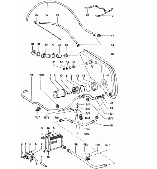 A shot of the foam seals for the filler neck and breather hose. 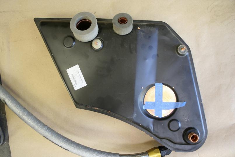 |
|
|
|
| raynekat |
Nov 21 2016, 12:09 AM
Post
#139
|
|
Advanced Member Group: Members Posts: 2,171 Joined: 30-December 14 From: Coeur d'Alene, Idaho Member No.: 18,263 Region Association: Pacific Northwest |
QUOTE(cary @ Nov 20 2016, 09:00 PM) Do you have #8, #9, #10, #11, #45 and #46 in your possession ? I'd like to get my hands on them before I cut the oi filter console hole. I've got all of those. I'll bring them to you right after Thanksgiving. The foam seals look good...maybe not quite so tall/thick? |
|
|
|
| cary |
Nov 24 2016, 12:23 PM
Post
#140
|
|
Advanced Member Group: Members Posts: 3,900 Joined: 26-January 04 From: Sherwood Oregon Member No.: 1,608 Region Association: Pacific Northwest |
Package showed up from Amazon. (IMG:style_emoticons/default/piratenanner.gif)
 We have a couple rear trunks (rotten back lips) we can cut a couple test holes into to test the seal fit. |
|
|
|
|
1 User(s) are reading this topic (1 Guests and 0 Anonymous Users)
0 Members:

|
Lo-Fi Version | Time is now: 17th July 2026 - 06:13 PM |
Invision Power Board
v9.1.4 © 2026 IPS, Inc.