|
|
|
Porsche, and the Porsche crest are registered trademarks of Dr. Ing. h.c. F. Porsche AG.
This site is not affiliated with Porsche in any way. Its only purpose is to provide an online forum for car enthusiasts. All other trademarks are property of their respective owners. |
|
|

  |

| cary |
 May 20 2017, 10:31 AM May 20 2017, 10:31 AM
Post
#221
|
|
Advanced Member  Group: Members Posts: 3,900 Joined: 26-January 04 From: Sherwood Oregon Member No.: 1,608 Region Association: Pacific Northwest |
Onto the inside. Looks like the hillbillies used a crow bar to open up the space for the inner sway bar support.
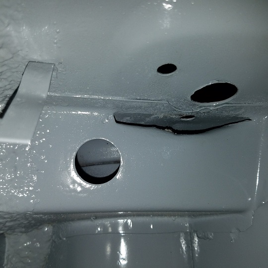 Trimmed it up the best I could without cutting out and welding in a new piece. 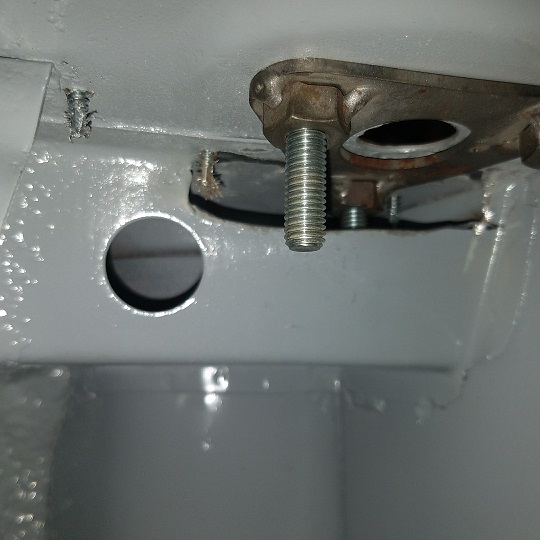 Left side all done. Right outer piece marked and ready for the band saw. Super In Law continues with the wheelhouse wall. Did a couple slits and welds to create the battery tray perch, turned out nice. With all the twists and turns its taking a bit get the cut out nice and tight. Big gap = hotter weld = a big melted mess. Patience is a virtue. Plus I have the luxury of not worrying about how long it's taking him. $$  The hard part is trying to recreate the circled portion without a bunch of hammer work. Won't spend too much time as its behind the battery tray. But it will nice and tidy. 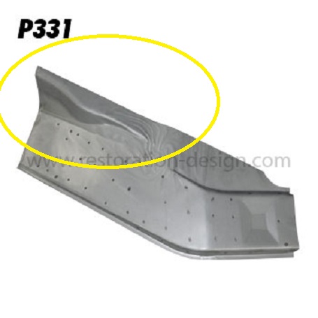 |
   |

 
|
| raynekat |
May 20 2017, 04:10 PM
Post
#222
|
|
Advanced Member Group: Members Posts: 2,171 Joined: 30-December 14 From: Coeur d'Alene, Idaho Member No.: 18,263 Region Association: Pacific Northwest |
QUOTE(cary @ May 20 2017, 09:14 AM)  I'll pull one of Mark's sway bar bushing cups out of his plating stash to check for welding clearance. Based on this shot there shouldn't be any issues. But I don't want it to be an issue after paint when Doug's putting it back together. (IMG:style_emoticons/default/sad.gif) I'll have to get you the ER sway bar bushing cups as they are a different shape than the factory ones....I think. Believe they are circular in shape not triangular like the factory. Cary....you're always thinking a couple steps ahead. |
|
|
|
| cary |
May 26 2017, 08:12 AM
Post
#223
|
|
Advanced Member Group: Members Posts: 3,900 Joined: 26-January 04 From: Sherwood Oregon Member No.: 1,608 Region Association: Pacific Northwest |
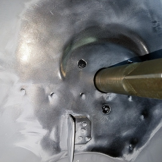
Made a house call and picked up Doug's front sway bar and bear blocks. That way I can make sure the sway bar is in side to side alignment. Tune it till it turns like butter.
Which is complicated a bit by welding in the tub stiffeners. The ER/Tarret bar add another complication. The bar is turned down the last 5 inches and won't go completely thru the bearing block. So I have to tear it all the way down each time I need to tweak the tub. (IMG:style_emoticons/default/sad.gif) 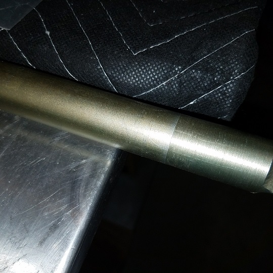 Had to run to Ace to get a larger UniBit. Up to 1 3/8. 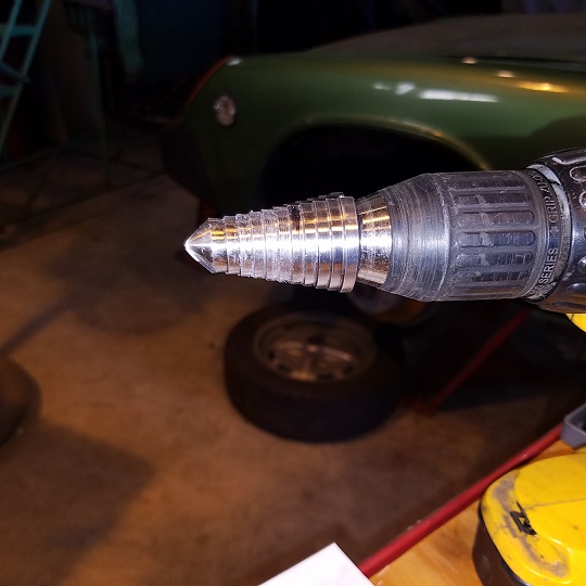 With the right side all locked down and tuned up straight. We'll lock down the left prior to tacking in the stiffener. 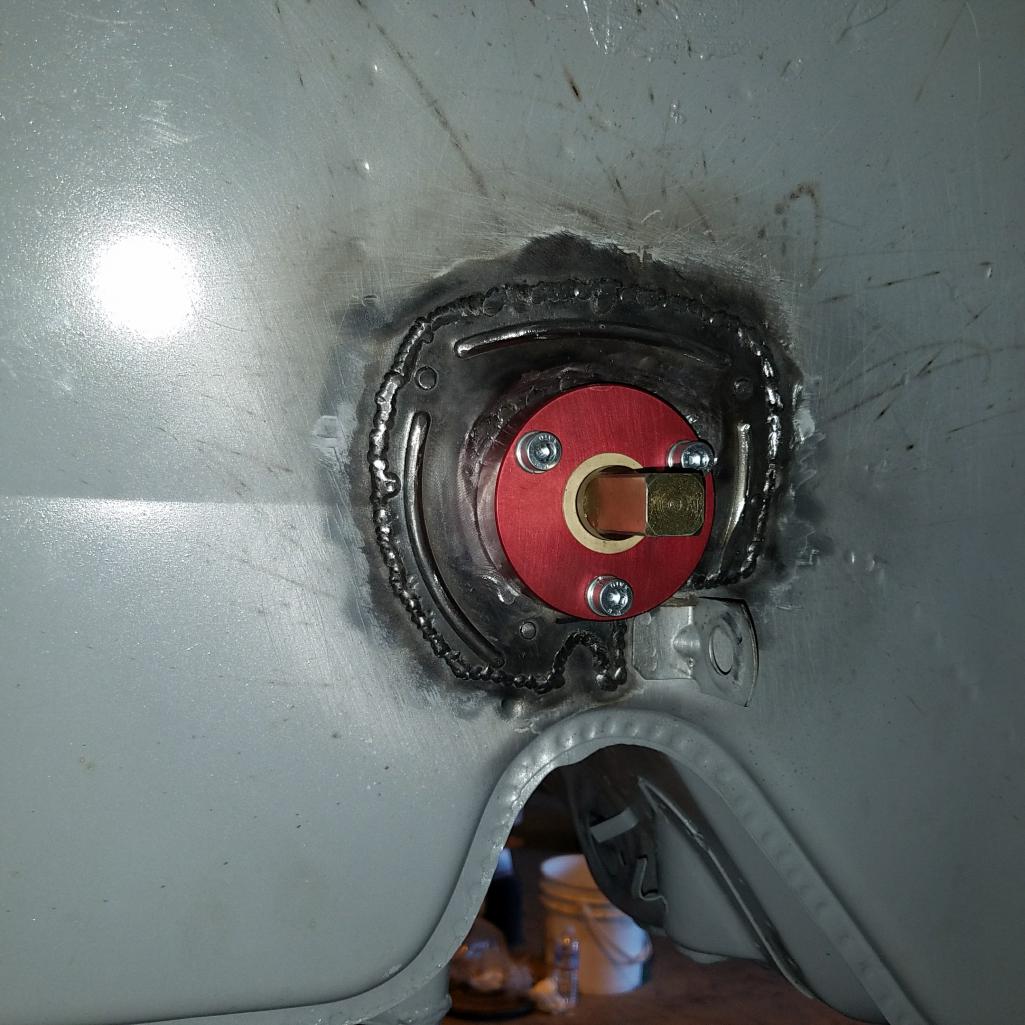 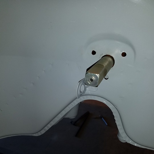 It took me a while but I can finally see the deviation in the tolerance as it come thru the bearing block. Josh at Rothsport had to beat on me a while. This allows you to know which way to tweak the tub. I will say its a little easier with the square cut end. Two corners will be tight. Two will show just the slightest gap. Ever so slight, 1000ths. |
|
|
|
| cary |
May 26 2017, 10:35 PM
Post
#224
|
|
Advanced Member Group: Members Posts: 3,900 Joined: 26-January 04 From: Sherwood Oregon Member No.: 1,608 Region Association: Pacific Northwest |
Here's a couple better shots of what I was trying to describe. The bar is being held by the left bearing but it is perfectly centered in the right hole.
  Here's the install of the left stiffener and bearing. 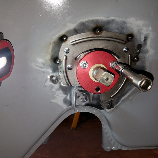 I used my factory sway bar support to pull the center pieces nice and tight. 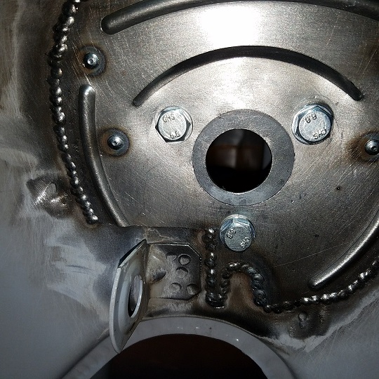 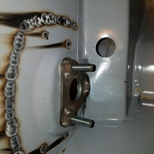 |
|
|
|
| cary |
May 26 2017, 10:47 PM
Post
#225
|
|
Advanced Member Group: Members Posts: 3,900 Joined: 26-January 04 From: Sherwood Oregon Member No.: 1,608 Region Association: Pacific Northwest |
After lunch it was time to start welding in the hell hole / wheel house patch panel.
It takes a lot of tuning and tinkering to get to a nice and tight fit. The bottom is tied back to the long. The rest I'll get to in the AM. 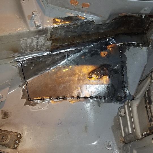 |
|
|
|
| cary |
May 28 2017, 09:34 AM
Post
#226
|
|
Advanced Member Group: Members Posts: 3,900 Joined: 26-January 04 From: Sherwood Oregon Member No.: 1,608 Region Association: Pacific Northwest |
Wheelhouse welded in and covered with cold galvanizing spray.
Slow and steady keeps it nice and flat. Used a 3" 36gr RoLoc on a 2" holder to smooth down the seam. Finish it with 80gr on a 3" mini DA. 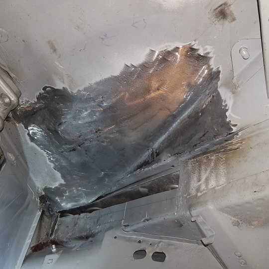 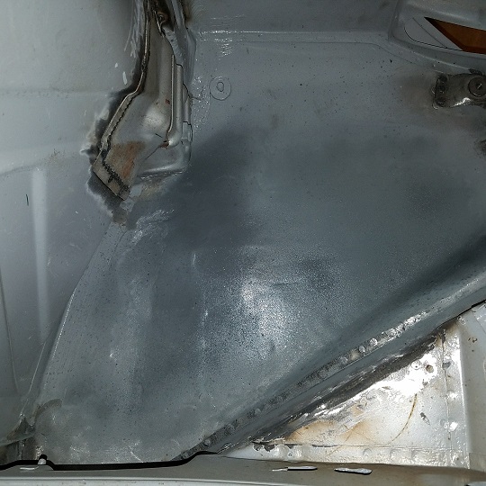 The hell hole ramp is about half way welded in. Forgot to shoot any pictures. Left early so I could stop at Immediate Care. (IMG:style_emoticons/default/mad.gif) Have some kind of cold I can't shake. |
|
|
|
| mb911 |
May 28 2017, 12:35 PM
Post
#227
|
|
914 Guru Group: Members Posts: 7,794 Joined: 2-January 09 From: Burlington wi Member No.: 9,892 Region Association: Upper MidWest |
Just did the exact same repair the same way. Great job.
|
|
|
|
| cary |
May 29 2017, 09:23 PM
Post
#228
|
|
Advanced Member Group: Members Posts: 3,900 Joined: 26-January 04 From: Sherwood Oregon Member No.: 1,608 Region Association: Pacific Northwest |
Took most of Sunday off to try and beat this virus ..............
Here's where we started this am (Monday). 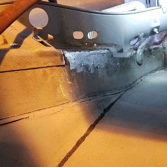 The top of the engine tray patch needs a little more polishing. But I won't get too carried away with it, it will all get covered up with seam sealer. 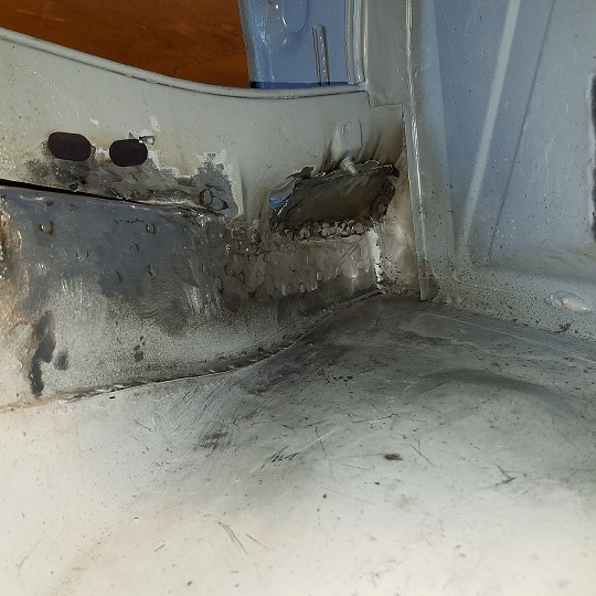 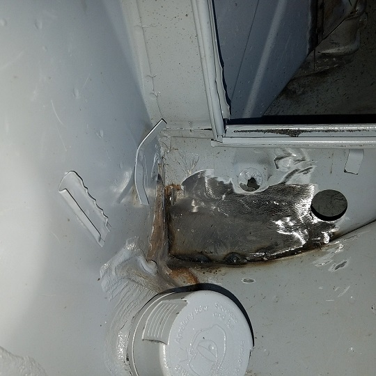 After a quick coating of cold galvanizing spray ...................... 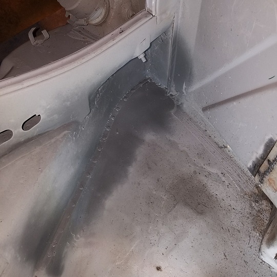 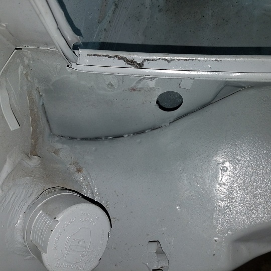 |
|
|
|
| cary |
Jun 10 2017, 12:10 AM
Post
#229
|
|
Advanced Member Group: Members Posts: 3,900 Joined: 26-January 04 From: Sherwood Oregon Member No.: 1,608 Region Association: Pacific Northwest |
Back from WCR and back to work.
Time to install the new battery tray combo.I decided to give Adam from RD's technique a shot. I usually install it in two pieces. This will make for an easier removal if needed in the future. https://www.youtube.com/watch?v=6ExKXK0UXpI 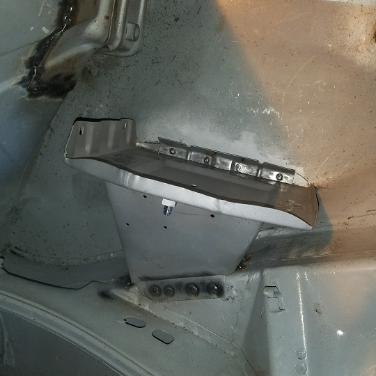 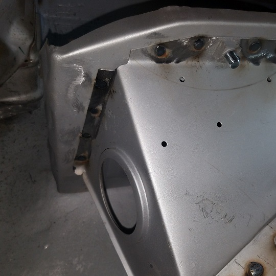 Trickiest part is the weld on the upper right side. Looked at 3 or 4 cars here at the shop and all had had their battery trays replaced. All had some pretty ugly welds on the right side. So I kept it pretty simple. Two long stick welds. Started the puddle on the long and pulled it up to the battery tray. 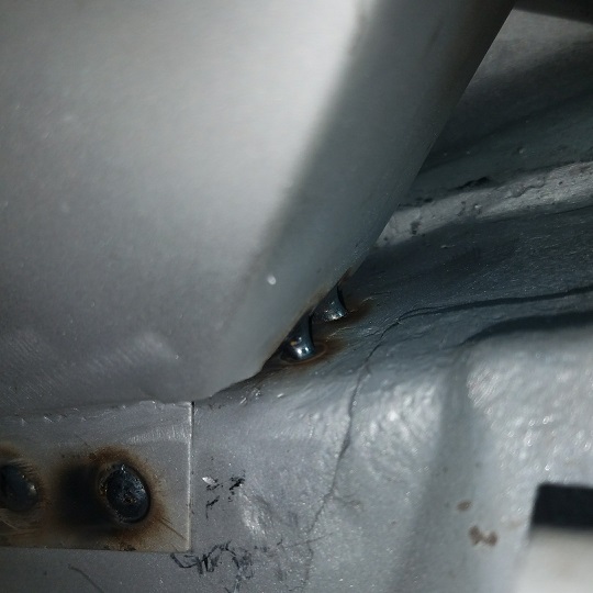 The RD pile of new parts is getting smaller. Plus the 1/2 floor pan. I'll start with the 6 cylinder motor mount in the am. 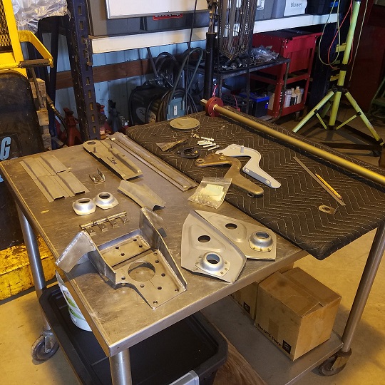 |
|
|
|
| cary |
Jun 10 2017, 11:23 PM
Post
#230
|
|
Advanced Member Group: Members Posts: 3,900 Joined: 26-January 04 From: Sherwood Oregon Member No.: 1,608 Region Association: Pacific Northwest |
Started the day with pulling out the plasma cutter. I cut the door seal channel section I need to replace/repair Doug's door from one of the doors off my POS parts car.
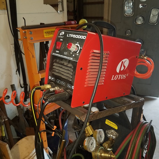 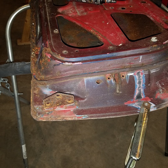 Took a bit of work but I got what I needed cut out. 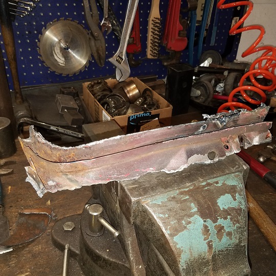 Then I trimmed it down some more ............... 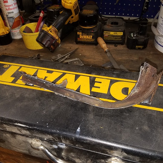 Here's what I ended up with. It will need a couple patches. But much better that what was there. Didn't look like much before I ran it thru the blast cabinet. 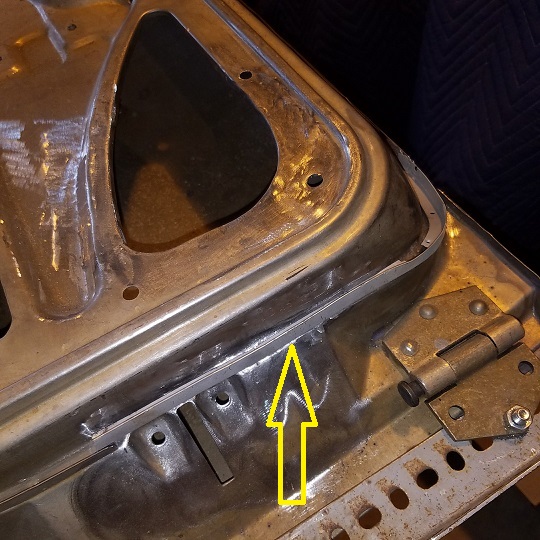 This piece was removed by drilling a hole thru the spot welds and slowly and softly chiseling off/out the spot welds without twisting the small piece. It takes a bit of patience. |
|
|
|
| cary |
Jun 11 2017, 09:16 AM
Post
#231
|
|
Advanced Member Group: Members Posts: 3,900 Joined: 26-January 04 From: Sherwood Oregon Member No.: 1,608 Region Association: Pacific Northwest |
Next Saturday Project :
Getting the parts car prepared to remove the cowl. Frunk hood, wiper motor, dash and misc. tidbits. After everything is cleared out of the way and I take the time to look at the spot welding. Getting the part out is going to be a bit tricky. The welded on fenders create quite dilemma. By itself, not a real issue with the Sawzall. But I might need the top of the fender too. Yet too be determined. 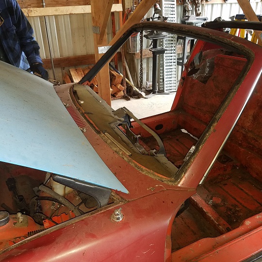 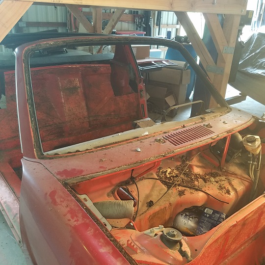 Here is the location I keep staring at. This is one of the worst spots for rust creeping back up and destroying a $10k plus paint job. The body tie is a fairly solid piece. But moisture gets in between the fender and cowl and the cancer begins. I remember when Jeff Hail was there on his project. But his fenders were off. http://www.914world.com/bbs2/index.php?s=&...t&p=1032628 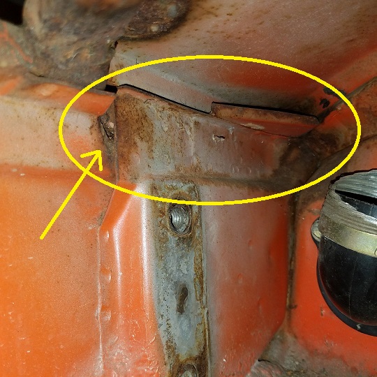 The problem is I want to save this portion too ................. We did this portion on my project car many years ago. But not both the fender and the cowl. 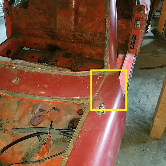 |
|
|
|
| cary |
Jun 11 2017, 09:31 AM
Post
#232
|
|
Advanced Member Group: Members Posts: 3,900 Joined: 26-January 04 From: Sherwood Oregon Member No.: 1,608 Region Association: Pacific Northwest |
Time to dive into the deep end .................
Went back and looked at the cowl on the project car. 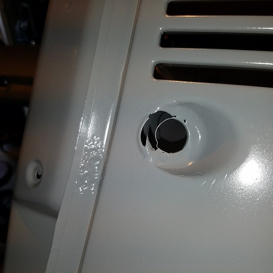 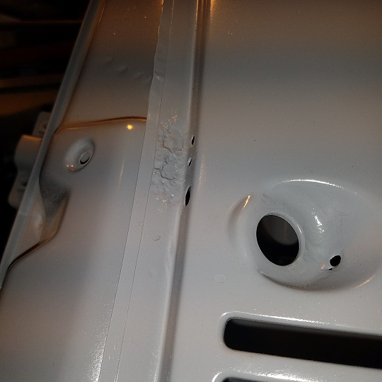 Wiper pivot holes ................ Its amazing what Bondo can cover up ............. (IMG:style_emoticons/default/mad.gif) 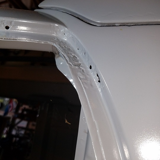 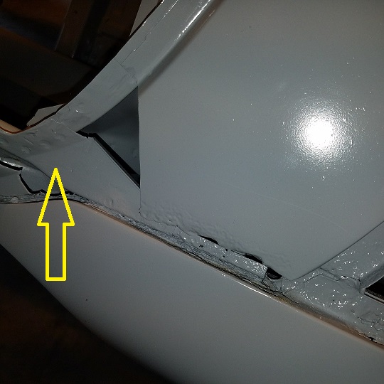 Tie in looks nice and solid. So out she came. 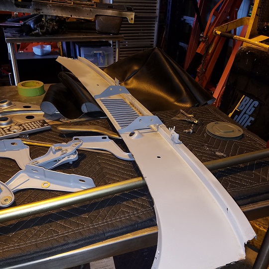 Cut line ................ 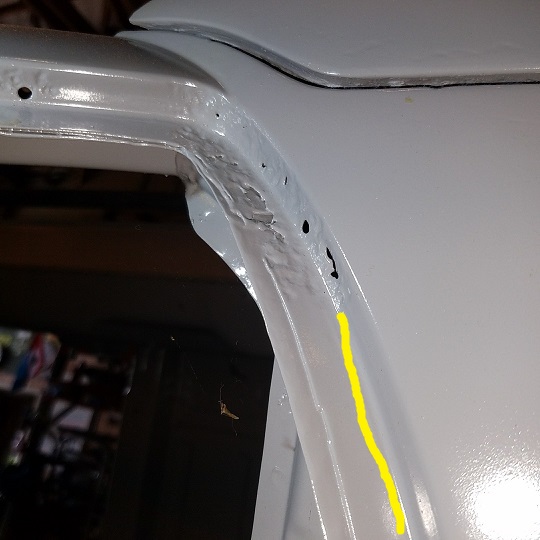 Time to walk out of the trauma center ............. |
|
|
|
| cary |
Jun 11 2017, 09:46 AM
Post
#233
|
|
Advanced Member Group: Members Posts: 3,900 Joined: 26-January 04 From: Sherwood Oregon Member No.: 1,608 Region Association: Pacific Northwest |
So lets go burn some metal ...............
Time for the 6 cylinder motor mount. 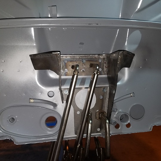 I did go back and grind down the welds in the center after the photo. 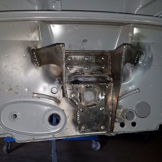 Went back and read Mark's comments on the alignment. Pretty straight forward, side to side centered (arrows). Then used the other two straight lines for the vertical. 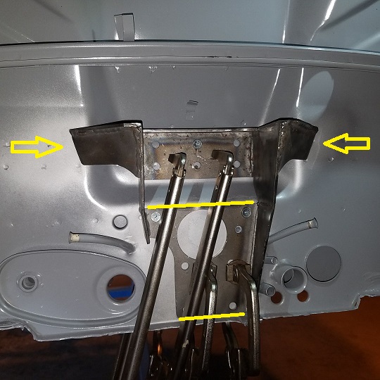 That was fun .................. (IMG:style_emoticons/default/welder.gif) |
|
|
|
| cary |
Jun 11 2017, 10:00 AM
Post
#234
|
|
Advanced Member Group: Members Posts: 3,900 Joined: 26-January 04 From: Sherwood Oregon Member No.: 1,608 Region Association: Pacific Northwest |
Back to trimming off/out the portion of the cowl I left on the dash flange.
This is what needs to come off ............. 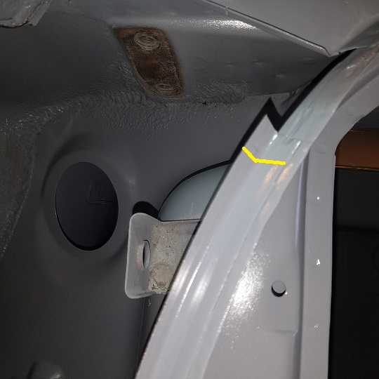 On we go ............ 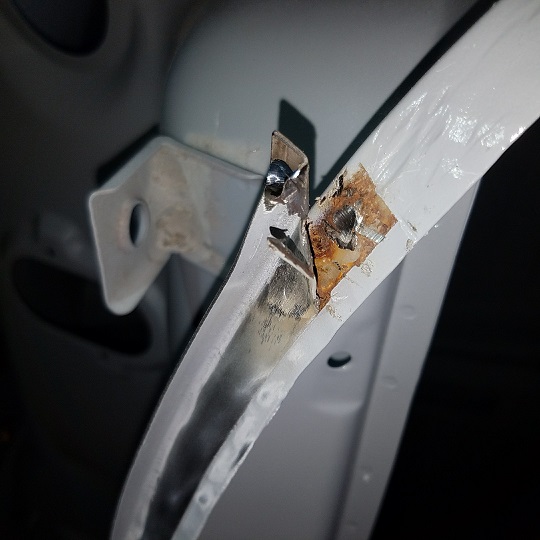 Ground off the primer to expose the spot welds. This time I used the nose of the belt sander to dig a hole in the spot weld. Didn't drill any holes. 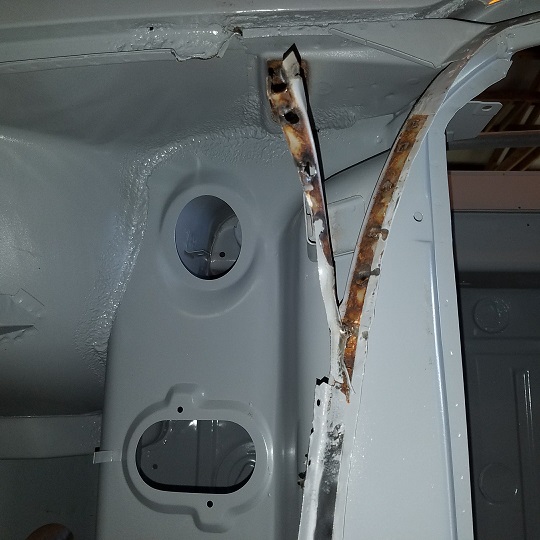 Took off about 6 inches at a time. |
|
|
|
| raynekat |
Jun 15 2017, 09:35 AM
Post
#235
|
|
Advanced Member Group: Members Posts: 2,171 Joined: 30-December 14 From: Coeur d'Alene, Idaho Member No.: 18,263 Region Association: Pacific Northwest |
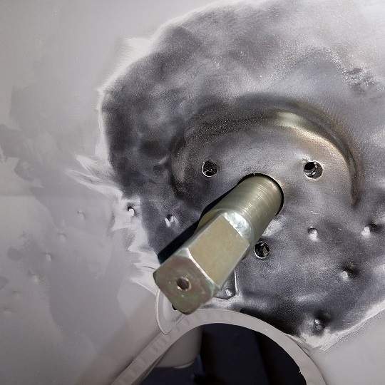
Finished up the engine side of the front 914-6 engine mount.
Rubber mount from URO (we'll give it a try as it's looks decent enough), main mount from Ben (of 914-6 SS heat exchanger fame) that was powder coated satin black and the 2 sandwich blocks from another Ben (thenewgarage 1970 914-6 - #2401 build thread). Ben's sandwich blocks are very nice and put to shame the shoddy set I received from Freisinger Motorsport in Germany....for a fraction of the cost too. Also all new hardware. 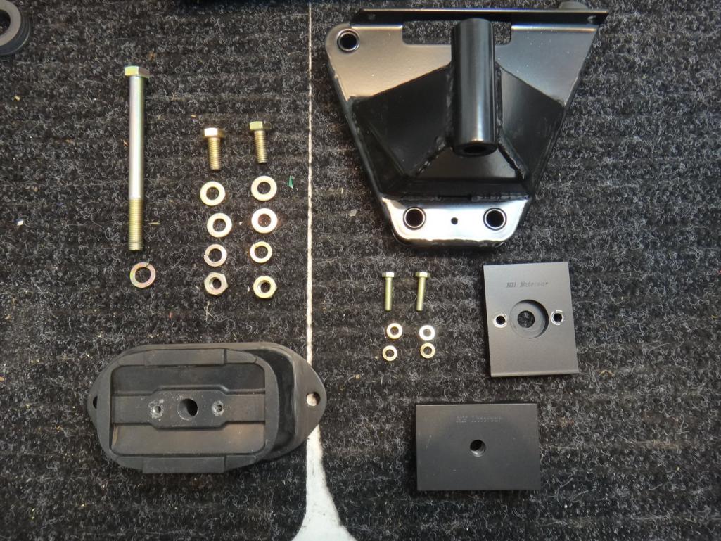 Fully assembled.... 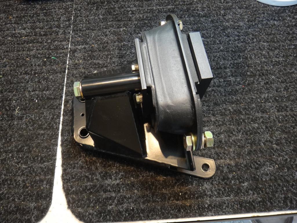 |
|
|
|
| raynekat |
Jun 15 2017, 09:40 AM
Post
#236
|
|
Advanced Member Group: Members Posts: 2,171 Joined: 30-December 14 From: Coeur d'Alene, Idaho Member No.: 18,263 Region Association: Pacific Northwest |
Quick clean up of the original jack.
Wanted a bit of patina on this one. Re-plated the springs in clear zinc and did all the bits and pieces in black oxide. Just cleaned up the main tube and gave that a quick home black oxide treatment using an Eastman kit. Painted the round base and the nose satin black. Good enough and preserves "some" of the character of the car. 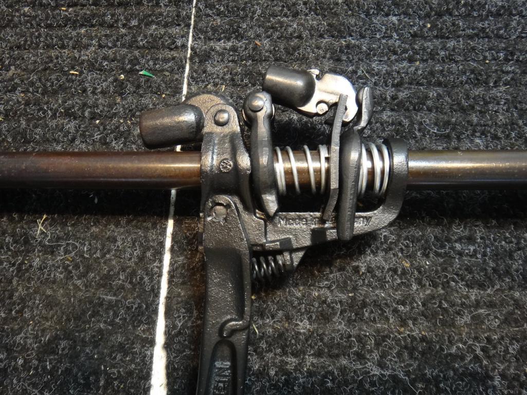 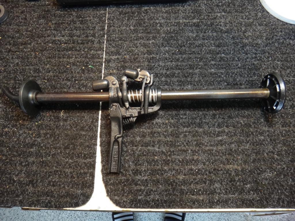 |
|
|
|
| raynekat |
Jun 15 2017, 09:49 AM
Post
#237
|
|
Advanced Member Group: Members Posts: 2,171 Joined: 30-December 14 From: Coeur d'Alene, Idaho Member No.: 18,263 Region Association: Pacific Northwest |
Just received these bad boys in the mail from Elephant Racing.
Bilstein sport shock with coil over conversion kit, 150# spring with helper. Hopefully a nice combination for predominantly street use with a bit of auto-cross and track days thrown in there as well. 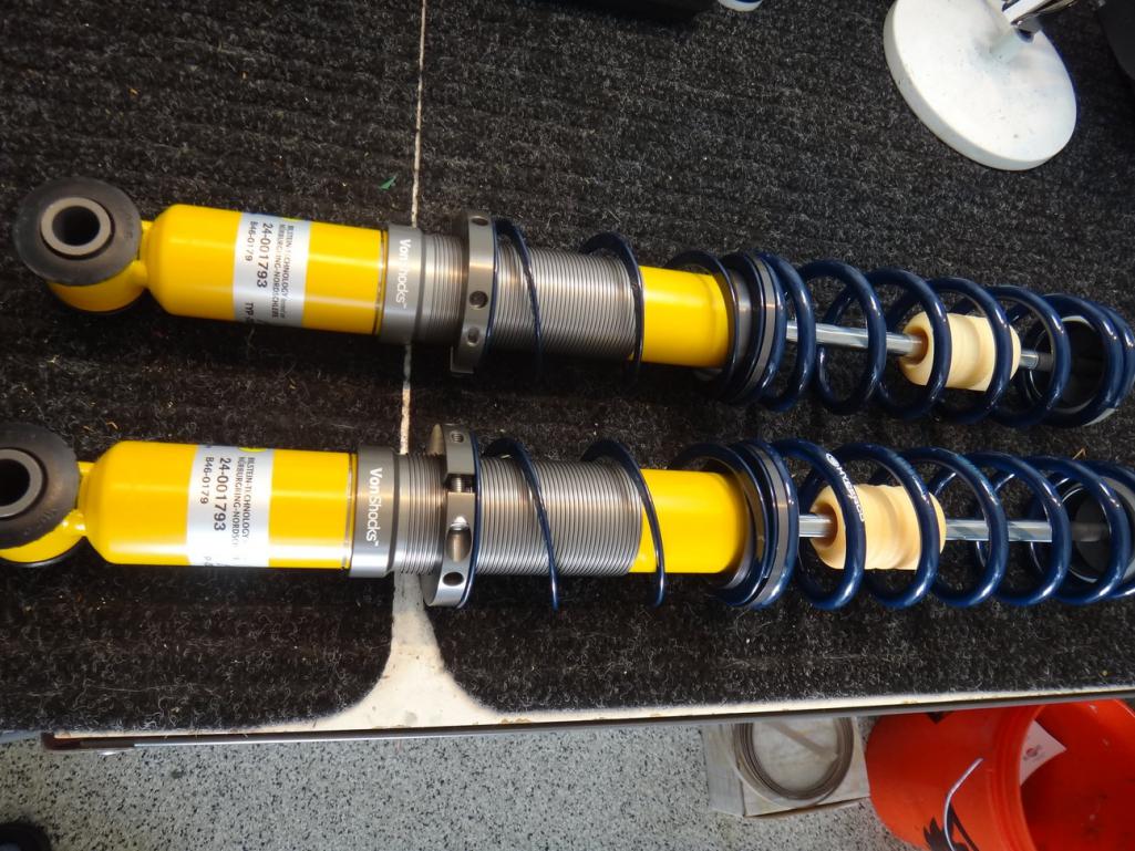 Love the decals with the Nurburgring on there.... 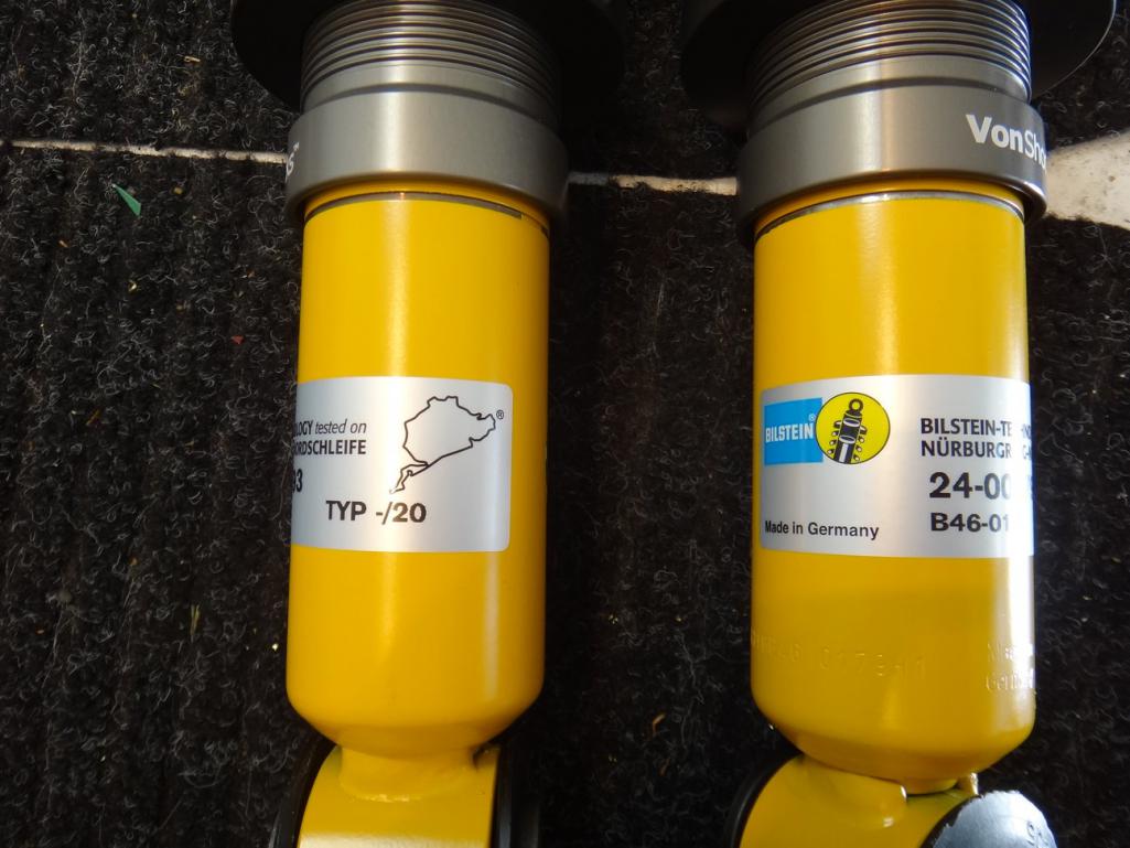 |
|
|
|
| cary |
Jun 16 2017, 08:56 AM
Post
#238
|
|
Advanced Member Group: Members Posts: 3,900 Joined: 26-January 04 From: Sherwood Oregon Member No.: 1,608 Region Association: Pacific Northwest |
Thursday 6.15.17
Welded in Super In Laws tuned up door seal channel. I'm pondering using JB Weld the seal channels on both door to eliminate the possibility of moisture getting back behind them again. Create a nice smooth surface. 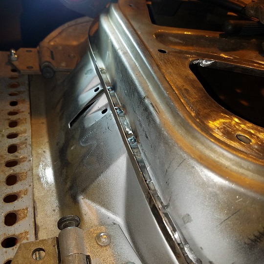 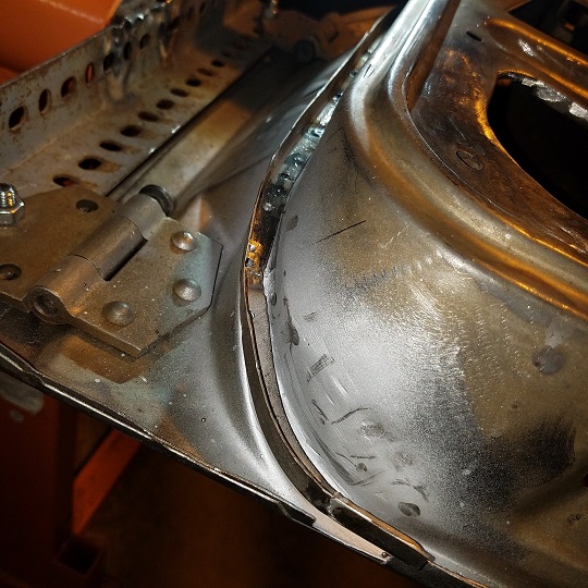 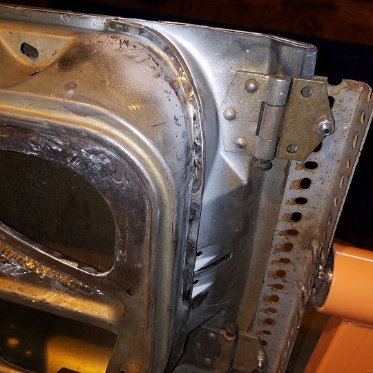 Next onto to cutting out the cowl. Kind of sacrificing a good fender to learn how its layered together. Because this was a CA car the channel looks to be solid all the way down. We'll melt the seam sealer out of the way once we get it completely removed. Then dig down to the cowl. Looks to be three layers deep. Trying to figure out which came first, the chicken or the egg. Then figure out how to recreate it. If I can without having to remove a section of the fender. (IMG:style_emoticons/default/barf.gif) 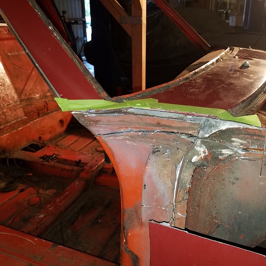 |
|
|
|
| mb911 |
Jun 16 2017, 10:43 AM
Post
#239
|
|
914 Guru Group: Members Posts: 7,794 Joined: 2-January 09 From: Burlington wi Member No.: 9,892 Region Association: Upper MidWest |
Looking good.. Tackling many of the same things on my car.
|
|
|
|
| cary |
Jun 16 2017, 10:51 PM
Post
#240
|
|
Advanced Member Group: Members Posts: 3,900 Joined: 26-January 04 From: Sherwood Oregon Member No.: 1,608 Region Association: Pacific Northwest |
(IMG:style_emoticons/default/sawzall-smiley.gif)
Out came the cowl/windshield frame. 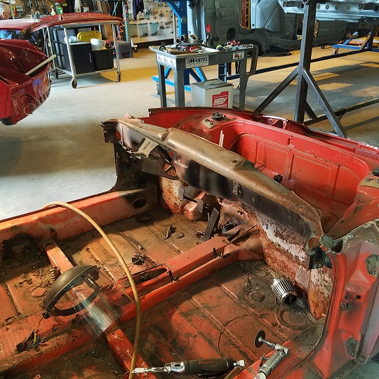 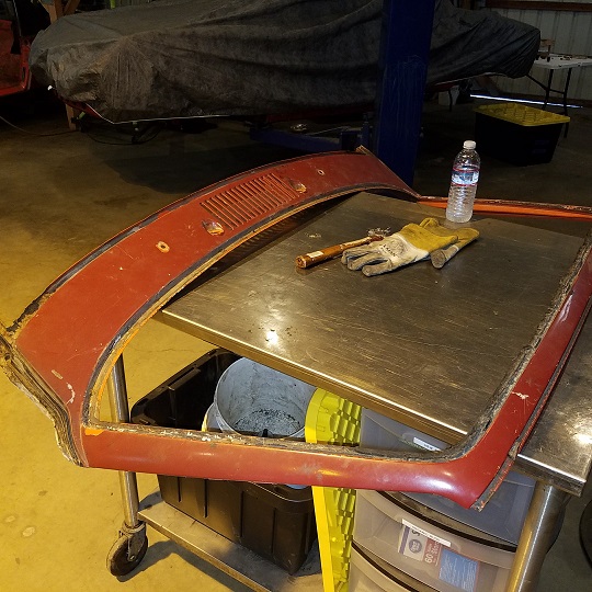 More info to come ............ forgot to shoot the pictures 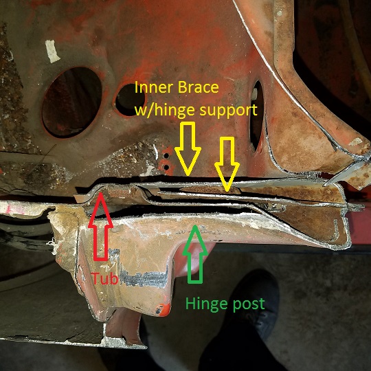 |
|
|
|
|
1 User(s) are reading this topic (1 Guests and 0 Anonymous Users)
0 Members:

|
Lo-Fi Version | Time is now: 17th July 2026 - 07:34 PM |
Invision Power Board
v9.1.4 © 2026 IPS, Inc.