|
|
|
Porsche, and the Porsche crest are registered trademarks of Dr. Ing. h.c. F. Porsche AG.
This site is not affiliated with Porsche in any way. Its only purpose is to provide an online forum for car enthusiasts. All other trademarks are property of their respective owners. |
|
|

  |

| cary |
 Jun 18 2017, 05:49 AM Jun 18 2017, 05:49 AM
Post
#241
|
|
Advanced Member  Group: Members Posts: 3,900 Joined: 26-January 04 From: Sherwood Oregon Member No.: 1,608 Region Association: Pacific Northwest |
Trimming down the cowl removed from the parts car. Trying to determine the assembly process as I'm peeling back the layers.
Starting point. Removing the fender portion first. The fender has a stiffener on the outside it supports an unknown air/drain gap that I didn't know existed. There's a 6 inch gap with no weld. 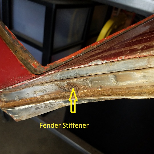 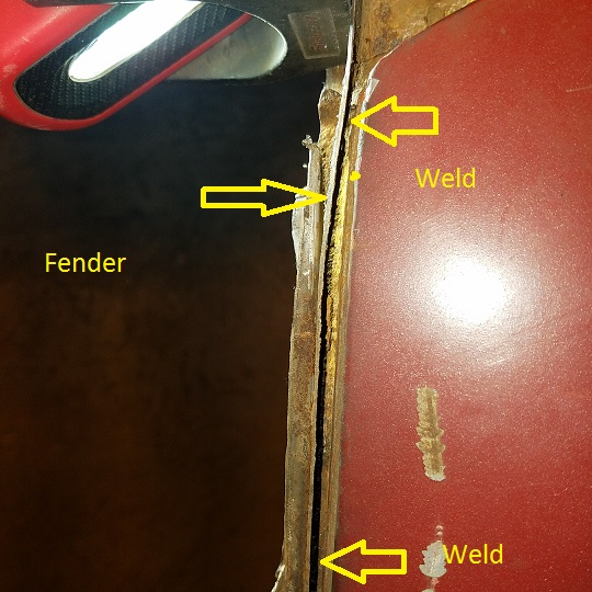 After fender portion removed ................. 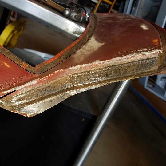 Lots more cut down pictures if someone needs more detail in the future. Cut off the window frame. 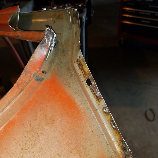 On to trimming the remaining dash portion off the cowl. 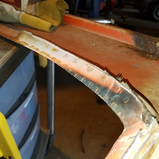 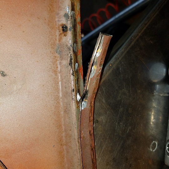 About ready for blasting ................ 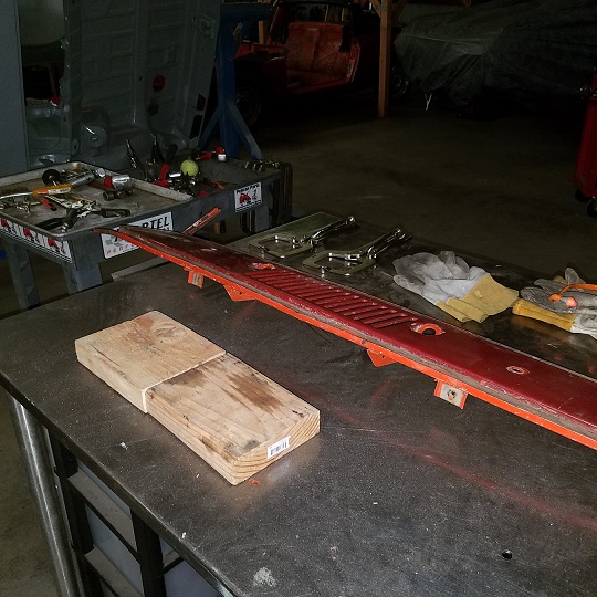 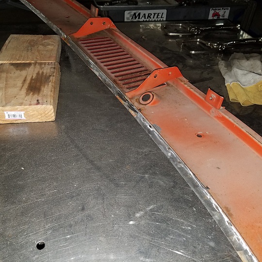 Working on cleaning out the gap on the project car. It's there, filled with debris and bondo. (IMG:style_emoticons/default/sad.gif) 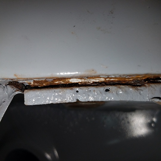 Next engineering issuse. What to fabricate to weld in the cowl at the fender joint. |
   |

 
|
| cary |
Jun 22 2017, 09:16 PM
Post
#242
|
|
Advanced Member Group: Members Posts: 3,900 Joined: 26-January 04 From: Sherwood Oregon Member No.: 1,608 Region Association: Pacific Northwest |
Thursday 6/22/17
First task before it gets too hot. Blast the replacement cowl. 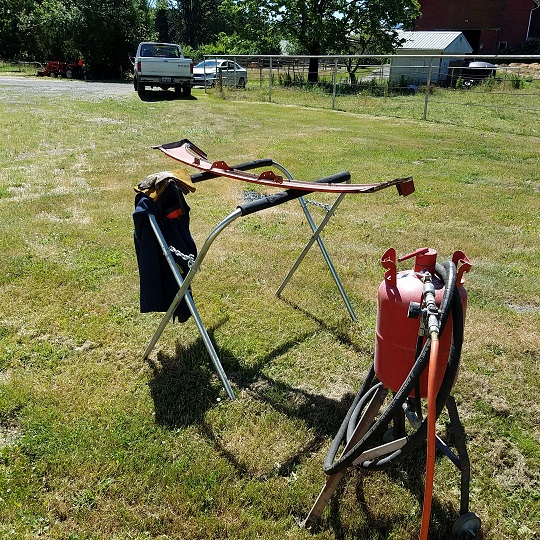 Then pulled the major dents out of the spare Leistritz muffler. It's ready to head to its new home after Doug gives it a paint job. 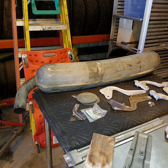 Then went to work on the 914-6 engine tin. This is the real deal. So it will need some tuning up. First obstacle to overcome is the attempt to repair with brazing years ago. 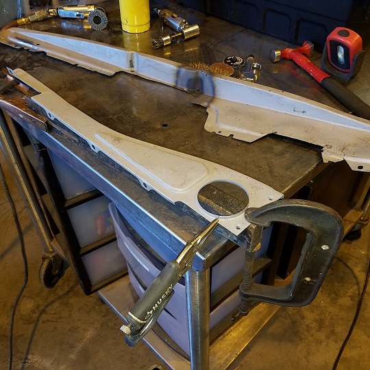 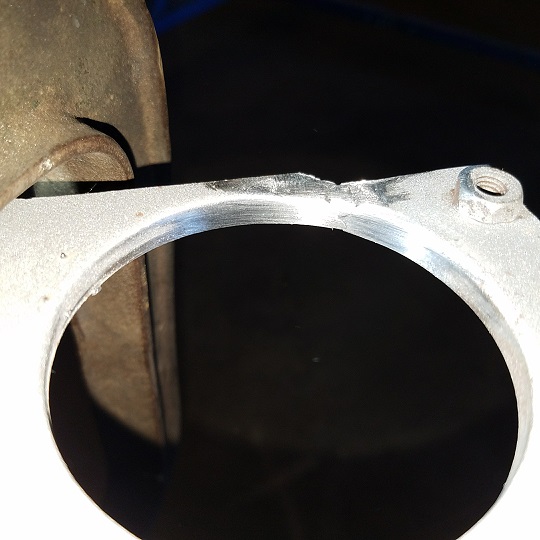  |
|
|
|
| cary |
Jun 24 2017, 07:16 AM
Post
#243
|
|
Advanced Member Group: Members Posts: 3,900 Joined: 26-January 04 From: Sherwood Oregon Member No.: 1,608 Region Association: Pacific Northwest |
As I wait for a couple inquiries Matt sent out on a nicer cowl I decided it was time to
R & R the pedal support. Like always I take it out in small sections so I don't rip the parent material underneath. I also used the RotoCut on this application. Didn't want to damage the floor pan. I did drill thru in one spot ................ (IMG:style_emoticons/default/sad.gif) 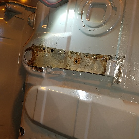 Prior to the application of cold galvanizing I welded up the pedal box water inlet. Things that make you go hmmmm. 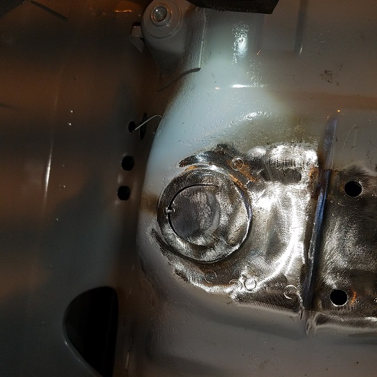 Bolted in then used 6 self tappers to snug it down tight. Still find the gas pedal holes in the new piece are a bit off. Have to elongate towards the pedal box. Cold galvanizing on the floor pan. U-Pol weld thru primer on the pedal support. I do remove the cold galvanizing with a squared off drill bit. I'm thinking much better penetration and a hell of a lot less weld thru primer splatter. (IMG:style_emoticons/default/smile.gif) 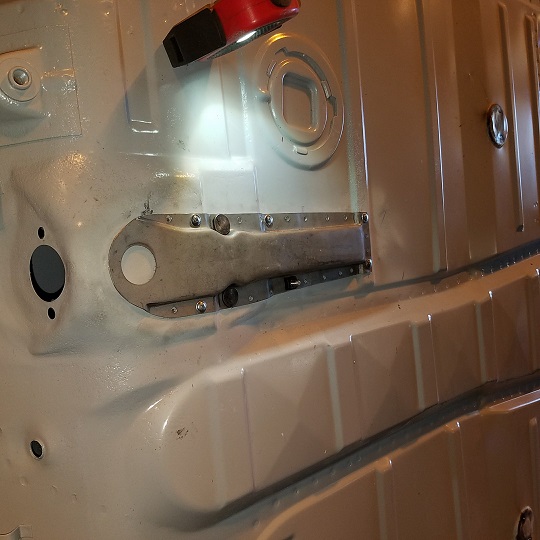 So while I'm burning metal I decide to weld up the other four water inlets on the front floor pan. Two had no cover and no seam sealer. Two had covers and a half ass application of seam sealer. So I glued them shut with the electric glue gun. 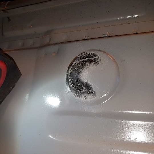 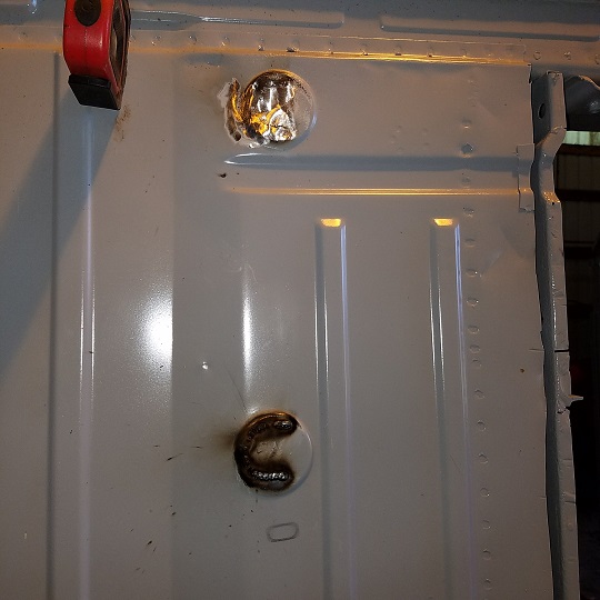 All tidied up ................... 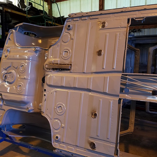 |
|
|
|
| cary |
Jun 24 2017, 07:26 AM
Post
#244
|
|
Advanced Member Group: Members Posts: 3,900 Joined: 26-January 04 From: Sherwood Oregon Member No.: 1,608 Region Association: Pacific Northwest |
Next project.
I'll have Super In Law build a new CDI hanger to hang it off the side of the battery tray. New one needs to turn 90 degrees. Plus we'll add a couple supports back to the battery tray base. This will give him a good chance to play with the bead roller. I just ordered the Woodward stand from Summit Racing. I have a feeling I'll have to buy the large set of dies too. 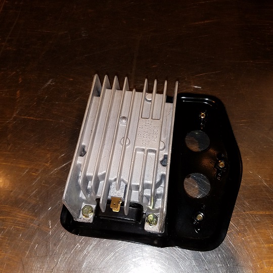 His next project will be carving a couple 3 or 4 wooden bucks to straighten out the trunk waves. I'll need to go shopping for a couple wooden mallets. |
|
|
|
| cary |
Jul 1 2017, 10:47 PM
Post
#245
|
|
Advanced Member Group: Members Posts: 3,900 Joined: 26-January 04 From: Sherwood Oregon Member No.: 1,608 Region Association: Pacific Northwest |
Today was the big day .................
Decided it was time to dig into fender to cowl rust. I'd been kind of dreading it. Seems I'm always cutting on a perfectly good car (words of Jeff Gamroth). And it I'm always the bearer of bad news when it comes to finding rust. Plus I have this long term since of responsibility to the paint that will cover my work. Decided I'd start with a small point of entry in case I get lucky and the tin worm hadn't started eating the second support layer of fender and the top of the hinge pillar. 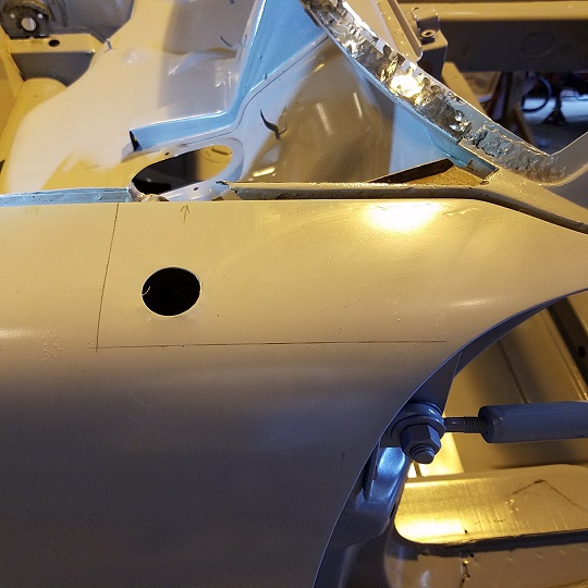 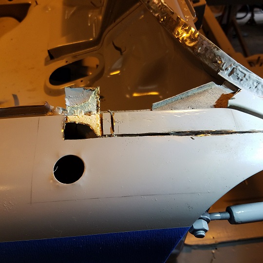 Looks like my conservative swing at it paid off ................ No rust in the usual places. (IMG:style_emoticons/default/biggrin.gif) The cleaned portion is the inner/lower layer of the fender. It doesn't seem to get much attention. 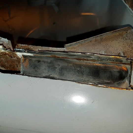 Cut out the top of the inner fender to get down to the channel where the rust is hiding. 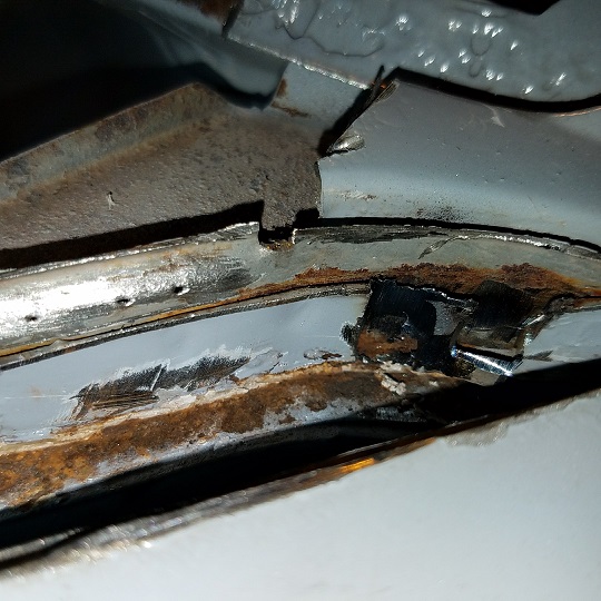 Keep cutting and digging. 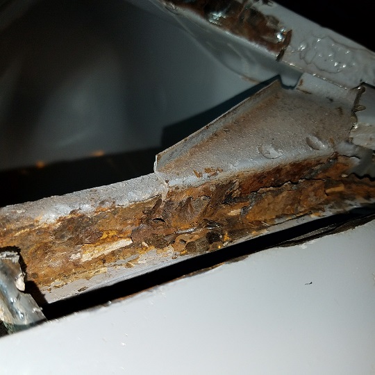 After peeling back the layers I got both sides opened up and treated with OSPHO. 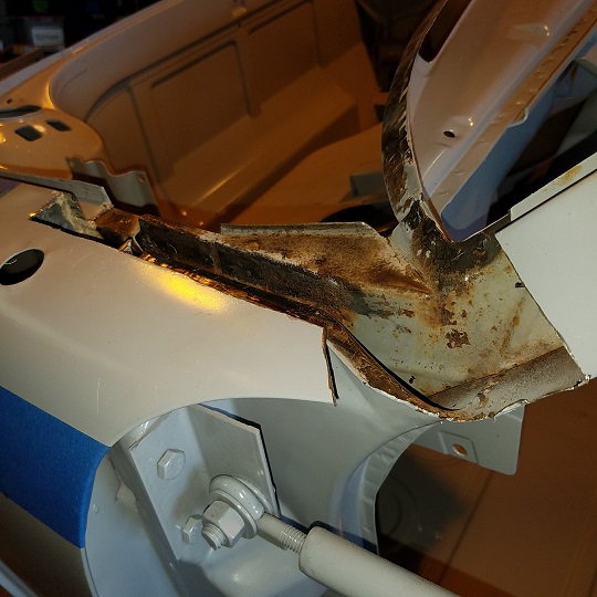 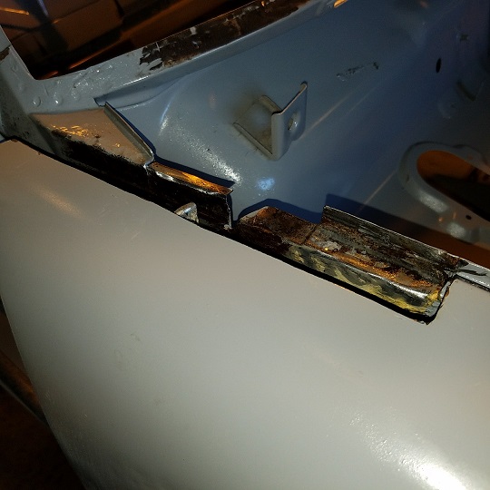 (IMG:style_emoticons/default/cheer.gif) (IMG:style_emoticons/default/cheer.gif) (IMG:style_emoticons/default/cheer.gif) (IMG:style_emoticons/default/cheer.gif) |
|
|
|
| cary |
Jul 7 2017, 10:08 PM
Post
#246
|
|
Advanced Member Group: Members Posts: 3,900 Joined: 26-January 04 From: Sherwood Oregon Member No.: 1,608 Region Association: Pacific Northwest |
Taking a break from the cowl/fender. Applied cold galvanizing spray to the cut out section after the OSPHO had dried.
It's time to install the back half of floor. 1st order of business is installing the seat adjuster mount for the right seat. NA on a 71. 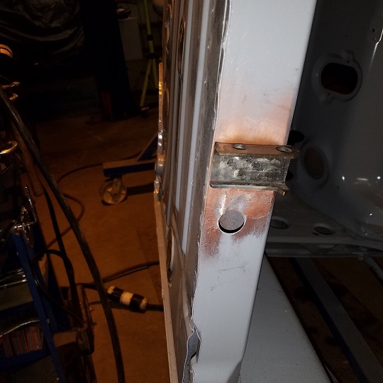 Then I sealed up the weld penetration from the 6 motor mount with cold galvanizing spray. 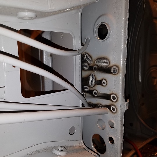 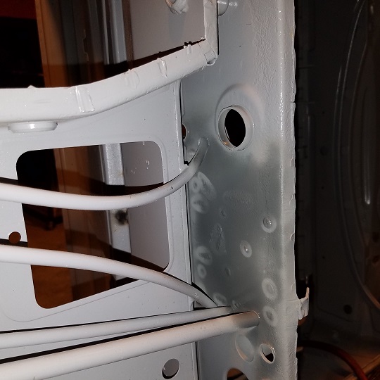 Then it was time to start tuning up all the nicks and cuts on the floor pan flange. 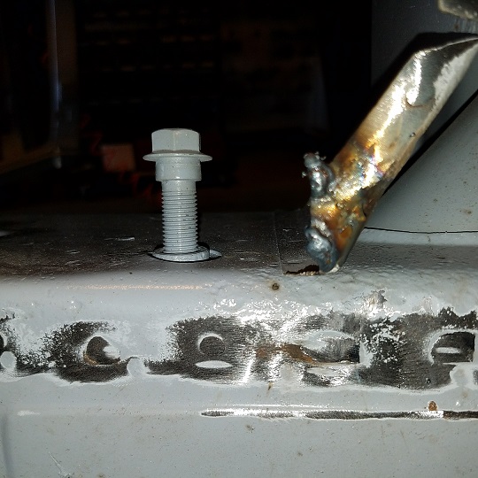 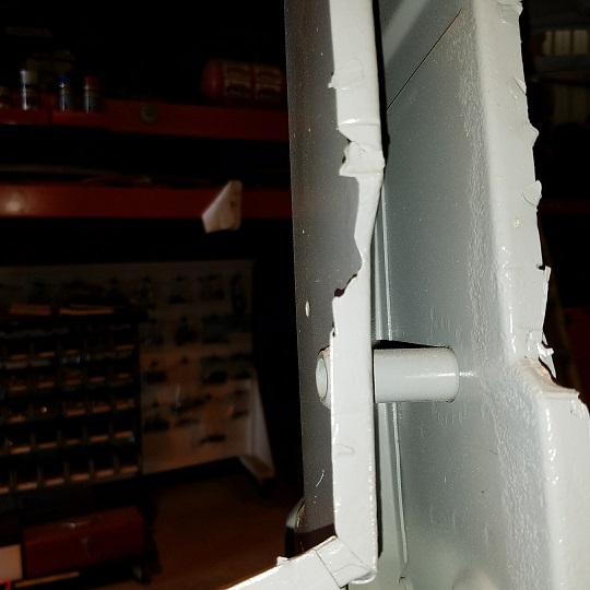 What couldn't be blipped in and welding is getting patched up. 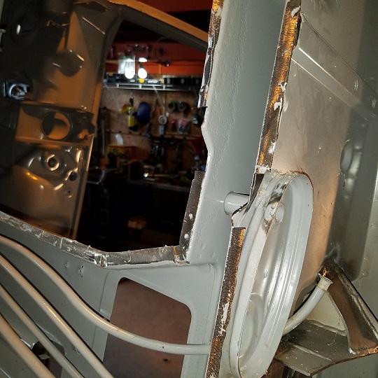 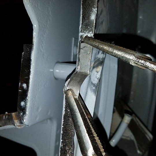 Tomorrows the day .................... 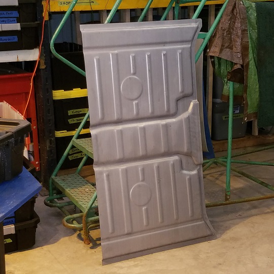 |
|
|
|
| Cairo94507 |
Jul 8 2017, 07:10 AM
Post
#247
|
|
Michael Group: Members Posts: 10,706 Joined: 1-November 08 From: Auburn, CA Member No.: 9,712 Region Association: Northern California |
Terrific work. (IMG:style_emoticons/default/beerchug.gif)
|
|
|
|
| cary |
Jul 8 2017, 08:52 AM
Post
#248
|
|
Advanced Member Group: Members Posts: 3,900 Joined: 26-January 04 From: Sherwood Oregon Member No.: 1,608 Region Association: Pacific Northwest |
Thank You .................
Today should be a big day. The rear floor pan is visually a big piece of the project. Then on to all the brake and seat tidbits ............. As I'm standing in the shower preparing for the day ahead. Forgot to mention that prepping the tunnel both the new rear bottom and the enclosed front is the first thing on the days agenda. I'll let that dry as I finishing the remaining patches. |
|
|
|
| cary |
Jul 11 2017, 08:19 AM
Post
#249
|
|
Advanced Member Group: Members Posts: 3,900 Joined: 26-January 04 From: Sherwood Oregon Member No.: 1,608 Region Association: Pacific Northwest |
Saturdays work ................ didn't quite get it welded in.
1st. Sprayed the new bottom with cold galvanizing spray. 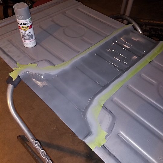 Then after some close inspection of the remaining tunnel I decided that it will need to be treated/sealed up. 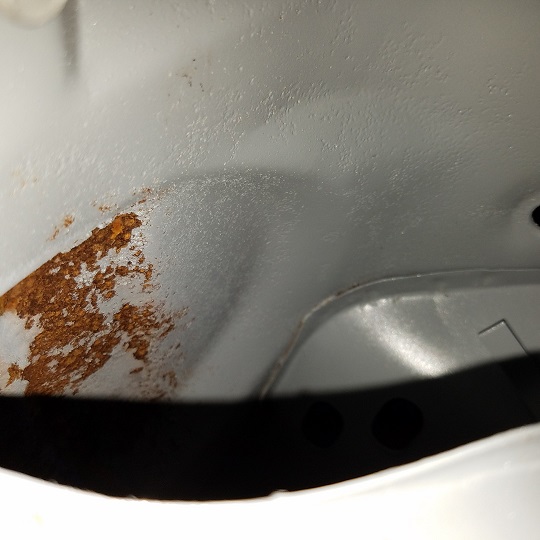 The blasting and epoxy primer didn't quite get in there. So I'd going to build a couple plugs for the cable tubes and we'll treat it with OSPHO then seal it up with frame coating. http://www.eastwood.com/eastwood-internal-...oz-aerosol.html Continued with bringing the flange back to 100%. A couple more patches and a few more nicks and cuts. 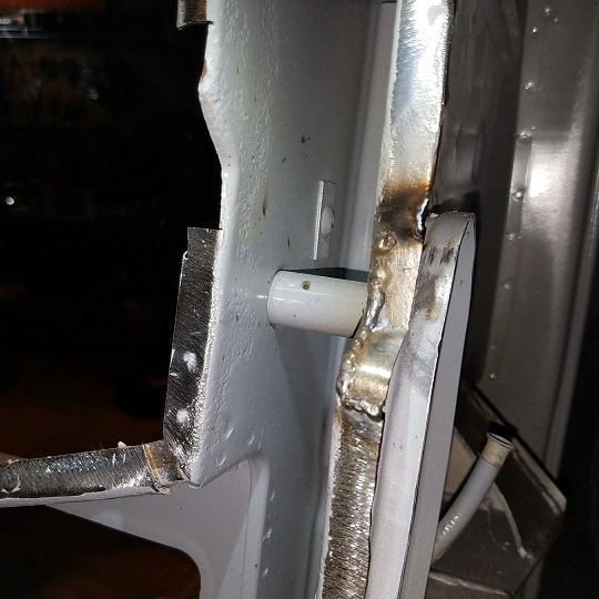 Before it gets smoothed down with the RoLoc disk. I'd decided that the 1/2" of excess material on the outside of the floor pan wasn't going to cut it on this car. So Super In Law built me a fence for my Jet band saw. 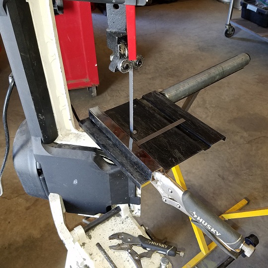 Forgot the before shot. But here's the after 1/2" was trimmed off. (IMG:style_emoticons/default/biggrin.gif) 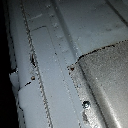 Now it fits into the recess like it should. Shot of the recess under the rear jack point. 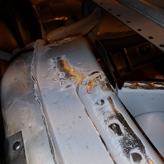 Now for the money cut. I like to put it under the cross member so its not seen. But it takes a bit of patience not to cut the tubes. 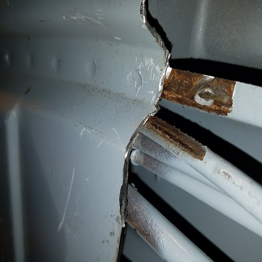 When it comes time to weld I'll pound out a piece of copper pipe to create a plate between the pipe and the weld. More on that later. Ready to be welded in after the tunnel gets treated.  |
|
|
|
| raynekat |
Jul 11 2017, 12:11 PM
Post
#250
|
|
Advanced Member Group: Members Posts: 2,171 Joined: 30-December 14 From: Coeur d'Alene, Idaho Member No.: 18,263 Region Association: Pacific Northwest |
That Eastwood internal frame coating system looks like a good way to go.
|
|
|
|
| Fatboy007 |
Jul 11 2017, 01:50 PM
Post
#251
|
|
Member Group: Members Posts: 62 Joined: 23-May 17 From: San Diego, ca. Member No.: 21,124 Region Association: Southern California |
Very nice...looks clean. (IMG:style_emoticons/default/biggrin.gif)
|
|
|
|
| cary |
Jul 21 2017, 10:17 PM
Post
#252
|
|
Advanced Member Group: Members Posts: 3,900 Joined: 26-January 04 From: Sherwood Oregon Member No.: 1,608 Region Association: Pacific Northwest |
Seems like I've been gone forever ....................
Thursday and Friday's work. 1. Finished up the muffler that Doug is selling to a friend here in PDX. 2. Blasted the remaining bondo from the donor cowl. (IMG:style_emoticons/default/sad.gif) . Not real pretty, but it can be fixed. Doug is going to scour the web for a new one. I asked Gary Emory at Parts Obsolete to dig thru his stash.  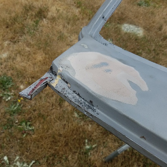 I could measure the bondo with a yardstick ................. pretty lazy work. 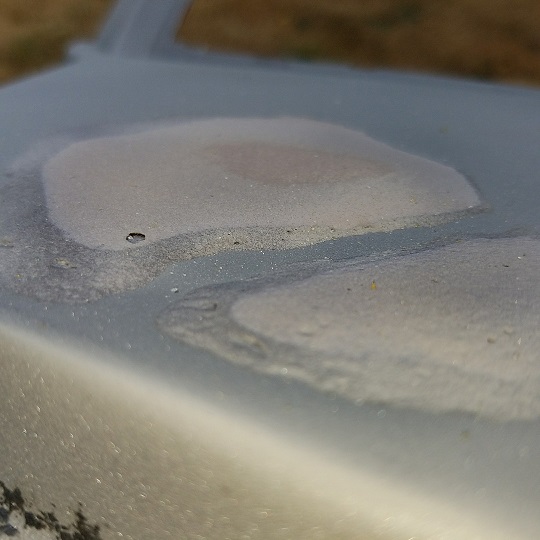 Super In law starting to work on the patch patterns ................. In Case It Needs To Be Used. 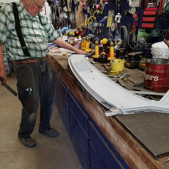 |
|
|
|
| cary |
Jul 21 2017, 10:39 PM
Post
#253
|
|
Advanced Member Group: Members Posts: 3,900 Joined: 26-January 04 From: Sherwood Oregon Member No.: 1,608 Region Association: Pacific Northwest |
Now the fun stuff, new metal.
Prepped the flanges with U-Pol Copper Weld Thru Primer. Way less splatter. 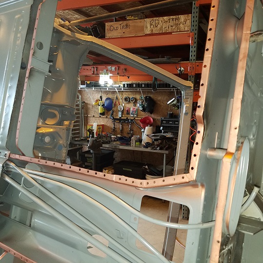 Built a removalable copper backer to protect the accelerator tube. 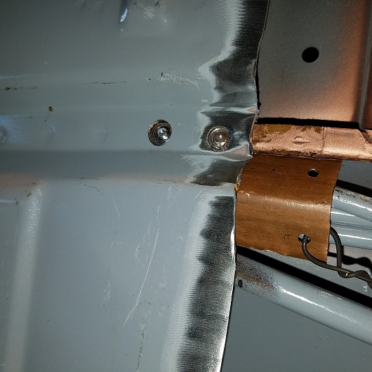 I like putting the seam under the center support. 1. I don't have to grind down the backside penetration which makes it stronger. 2. The obvious, its hidden. Both the center support and tunnel will be coated with Eastwood Frame Coating. Downside you can't use butt weld clamps so its pretty tedious and slow going. Basically I tune the butt weld perfectly flat one inch at a time. Making a stitch about every inch. Then come back and link the stitches. Used self taping screws in every other rosette hole. 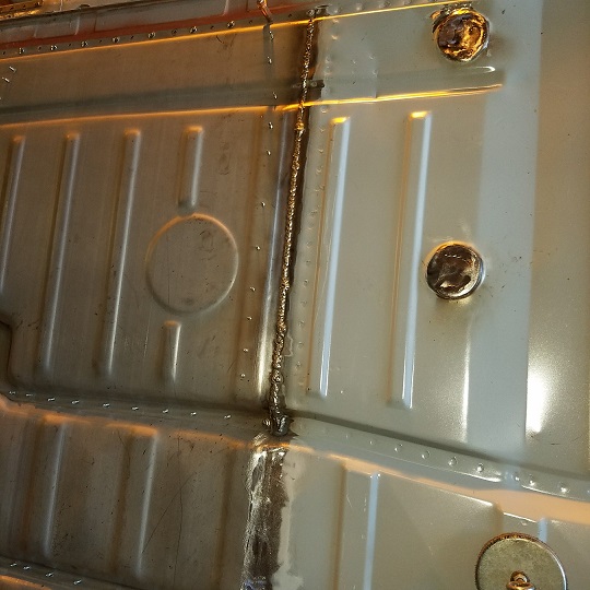 Butt weld complete and finished up ................... (IMG:style_emoticons/default/biggrin.gif) 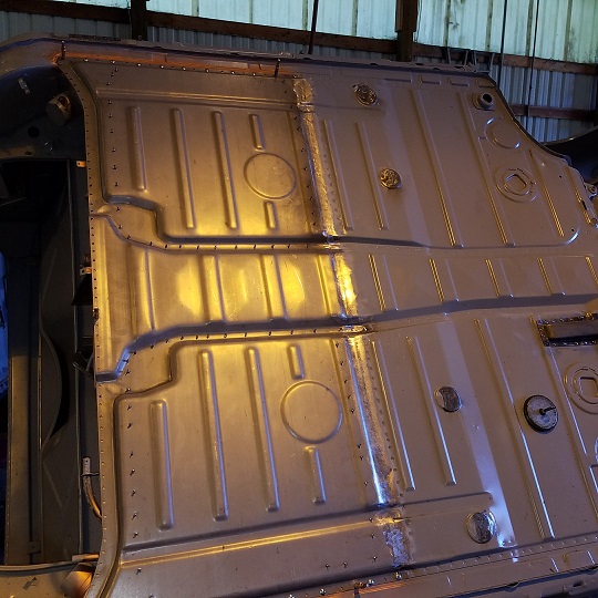 You don't need to over grind, this will be schutzed. |
|
|
|
| raynekat |
Jul 22 2017, 03:44 PM
Post
#254
|
|
Advanced Member Group: Members Posts: 2,171 Joined: 30-December 14 From: Coeur d'Alene, Idaho Member No.: 18,263 Region Association: Pacific Northwest |
Just received back some parts from Burnham Performance out of Camarillo, CA.
Can highly recommend them. The turnaround wasn't much over 2 weeks time. First were my MFI throttle bodies that were bored out to S/RS spec (engine will be a 2.7 RS MFI). Larger butterflies installed. Everything re-plated with a Dow coating for the throttle bodies themselves. Works of art I think. Love the detail. 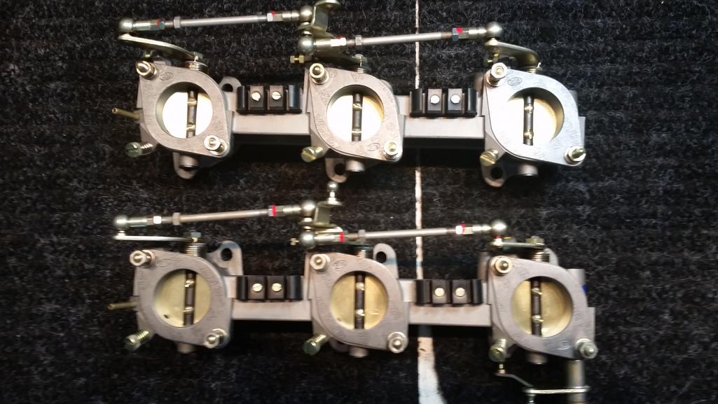 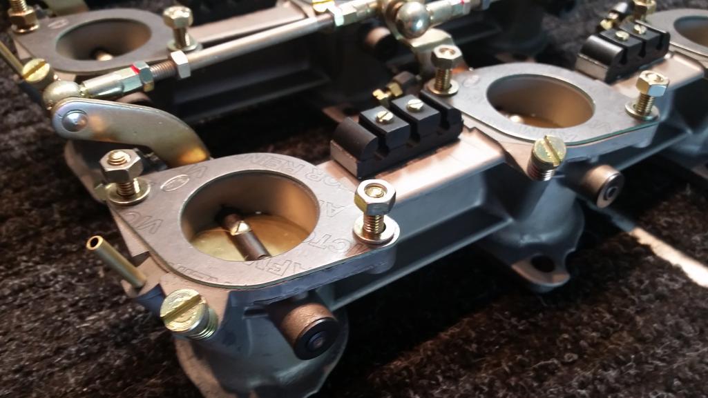 |
|
|
|
| raynekat |
Jul 22 2017, 03:46 PM
Post
#255
|
|
Advanced Member Group: Members Posts: 2,171 Joined: 30-December 14 From: Coeur d'Alene, Idaho Member No.: 18,263 Region Association: Pacific Northwest |
Secondly, Burnham Performance restored and recurved my Bosch distributor again to RS specs.
Another great job by them. I added a set of Pertronix magnetic points to finish it up. 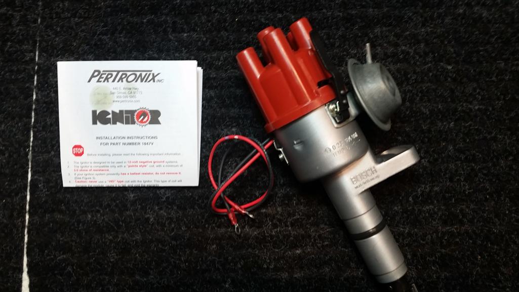 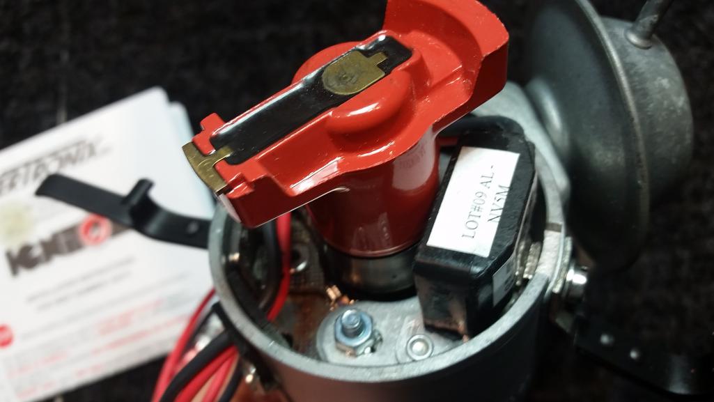 |
|
|
|
| raynekat |
Jul 23 2017, 08:30 PM
Post
#256
|
|
Advanced Member Group: Members Posts: 2,171 Joined: 30-December 14 From: Coeur d'Alene, Idaho Member No.: 18,263 Region Association: Pacific Northwest |
One of the fun parts about doing a 914-6 conversion is coming up with a game plan for the wiring harness action in the engine bay.
Going from a 914-4 wiring harness through a 914-6 engine relay board and interfacing it all with an MFI engine does have it's challenges. I wanted to make use of as much of the existing wiring in the 914-4 wiring harness as possible. Also needed to use the 914-6 relay as there is something called an RPM transducer (or speed switch) that is nice to have with an MFI system to eliminate backfiring on deaccerlation. Plus I'm going "old school" and using the on board voltage regulator vs. a built-in regulator in the alternator (newer ones are this way). 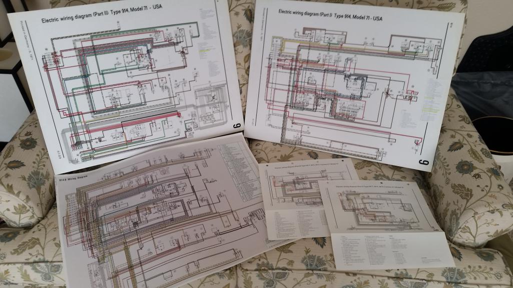 So here's me with wiring diagrams for a 1971 914-4, 914-6, and 1973 911 E,S,RS trying to figure out what goes where. This was made all the more challenging by the fact that my wife and I just had twins. Talk about reinventing the wheel a couple of times. I'd get so far with my plan of action then it was time for the twins. Then where was I? How far did I get? Maddening really, but eventually I got there. Had to learn how the std Porsche round relays worked, how the cold start relay and accompanying thermo-time switch works, and how the RPM transducer and fuel shutoff solenoid on the MFI pump worked. After that....simple as connecting the dots. I'll have to add a couple of additional wires down the tunnel for the different 911 gauges I'll be using....oil pressure/oil temp. But everything else can be dovetailed into the existing wiring. Even on the 914-6 engine relay board, I'm repurposing the rear window heater relay as the fuel pump relay. Eventually, I put together my own 914-6 relay panel current flow/wiring diagram. |
|
|
|
| raynekat |
Jul 23 2017, 08:36 PM
Post
#257
|
|
Advanced Member Group: Members Posts: 2,171 Joined: 30-December 14 From: Coeur d'Alene, Idaho Member No.: 18,263 Region Association: Pacific Northwest |
All the various switches and relays attached.
Nice NOS 1971 914-4 chassis wiring harness that I purchased from Aase Porsche many moons ago. Of course laying this all out in the comfort of my air-conditioned office at home. 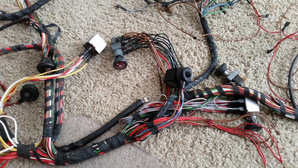 |
|
|
|
| raynekat |
Jul 23 2017, 08:37 PM
Post
#258
|
|
Advanced Member Group: Members Posts: 2,171 Joined: 30-December 14 From: Coeur d'Alene, Idaho Member No.: 18,263 Region Association: Pacific Northwest |
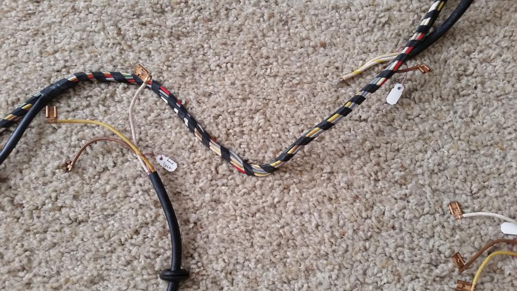
Every wire connection identified, traced, confirmed and labeled for later installation into the chassis.
 |
|
|
|
| cary |
Aug 1 2017, 07:52 AM
Post
#259
|
|
Advanced Member Group: Members Posts: 3,900 Joined: 26-January 04 From: Sherwood Oregon Member No.: 1,608 Region Association: Pacific Northwest |
It's time for the throw down to begin ............
I'm taking a couple weeks off from Rothsport to focus on getting Doug's car finished up. Looks like a I could have timed it a little better. PDX forecast for the next few days, over 100. (IMG:style_emoticons/default/welder.gif) |
|
|
|
| tygaboy |
Aug 1 2017, 07:56 AM
Post
#260
|
|
914 Guru Group: Members Posts: 5,844 Joined: 6-October 15 From: Petaluma, CA Member No.: 19,241 Region Association: Northern California |
Beautiful work... I could watch it all day.
|
|
|
|
|
1 User(s) are reading this topic (1 Guests and 0 Anonymous Users)
0 Members:

|
Lo-Fi Version | Time is now: 17th July 2026 - 08:22 PM |
Invision Power Board
v9.1.4 © 2026 IPS, Inc.