|
|
|
Porsche, and the Porsche crest are registered trademarks of Dr. Ing. h.c. F. Porsche AG.
This site is not affiliated with Porsche in any way. Its only purpose is to provide an online forum for car enthusiasts. All other trademarks are property of their respective owners. |
|
|

  |

| cary |
 Oct 17 2017, 10:54 PM Oct 17 2017, 10:54 PM
Post
#361
|
|
Advanced Member  Group: Members Posts: 3,900 Joined: 26-January 04 From: Sherwood Oregon Member No.: 1,608 Region Association: Pacific Northwest |
Won't be too many pictures the next couple days. Lots of itty bitty detail work.
Starting with the fit on the outside edge. Its the first place I look on every car. 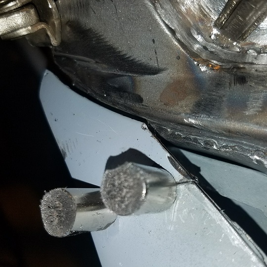 Shot for Doug ................ 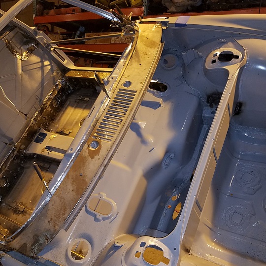 Decided to clean off the flash rust with Ospho and a red 3m pad. 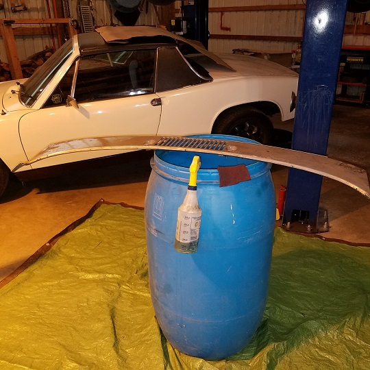 |
   |

 
|
| cary |
Oct 17 2017, 11:19 PM
Post
#362
|
|
Advanced Member Group: Members Posts: 3,900 Joined: 26-January 04 From: Sherwood Oregon Member No.: 1,608 Region Association: Pacific Northwest |
Go back to post #241 to look at the cut out/back of the fender to cowl joint.
|
|
|
|
| cary |
Oct 18 2017, 01:22 PM
Post
#363
|
|
Advanced Member Group: Members Posts: 3,900 Joined: 26-January 04 From: Sherwood Oregon Member No.: 1,608 Region Association: Pacific Northwest |
Thursday 10/18/2017
We begin the reverse engineering of the cowl to fender joint. Started with a shot from the Metal Surgeons first 914 World 914-6 restoration I believe. 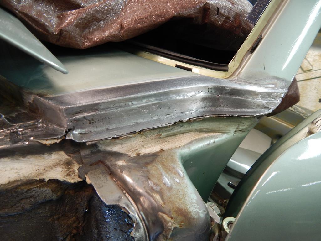 Emailed Pete at RD to see if they have a cowl/windshield in the NOS stash. If so, if he could send me some detail on the joint. Then I dug into my own stash of harvested parts and found some more detail. 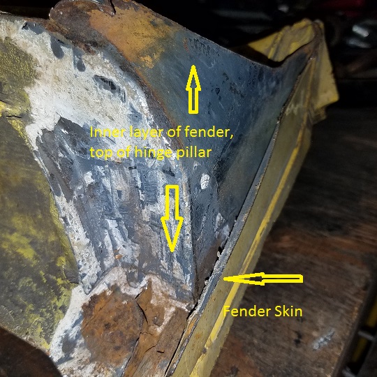 Super In Law has his thinking cap on ............ 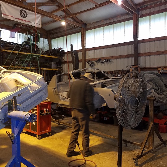 First thing this AM I red padded the Ospho'd cowl and paint the under side with cold galvanized in case it gets missed on the epoxy touch up before paint. 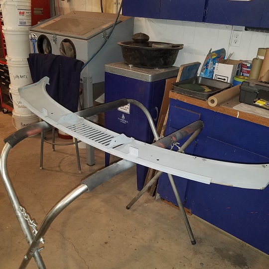 |
|
|
|
| cary |
Oct 19 2017, 08:52 AM
Post
#364
|
|
Advanced Member Group: Members Posts: 3,900 Joined: 26-January 04 From: Sherwood Oregon Member No.: 1,608 Region Association: Pacific Northwest |
The hinge post gave me all the info I needed for the reverse engineering.
Here's a shot of the backside of the hinge post after all the seam sealer was removed with the torch. 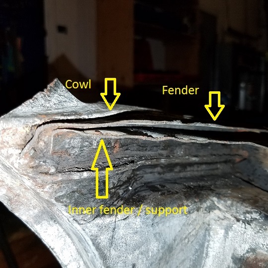 Here's a shot of what some have called the inner layer. It's actually the front fender support. 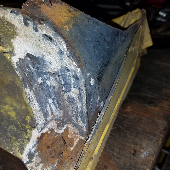 Here's a shot of the backside of that piece. Circled in yellow. Photo is the Metal Surgeons created part. 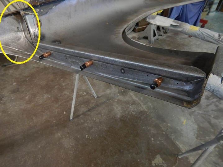 Here's my poor use of Paint giving you an idea of what we're going to recreate to replace the rotten section I cut out back in July. 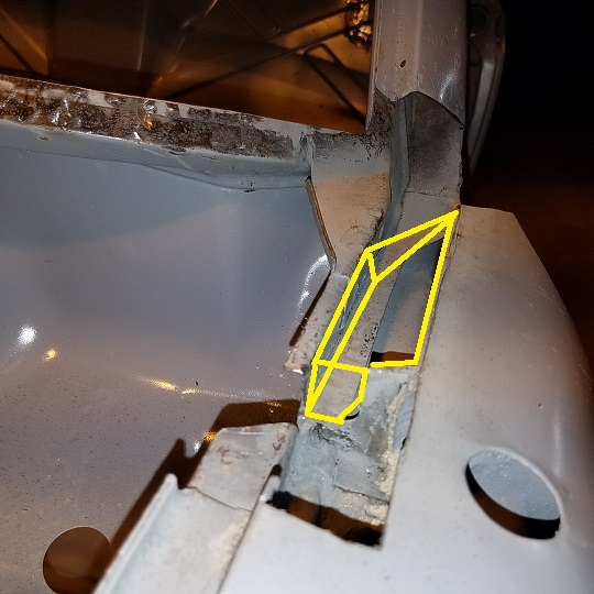 Super In Law top pieces he's been working on in the other room. 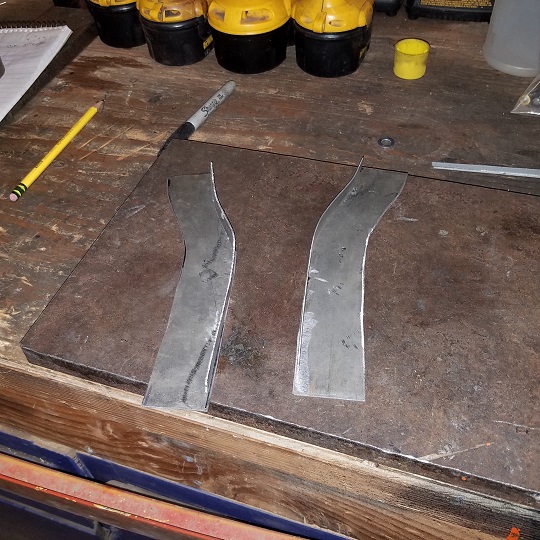 With the plan all set in our minds it was time to fit the cowl to the windshield frame. The frame had to be opened up earlier so I could get it to lay the flat. Here's a shot of the extension added back on. 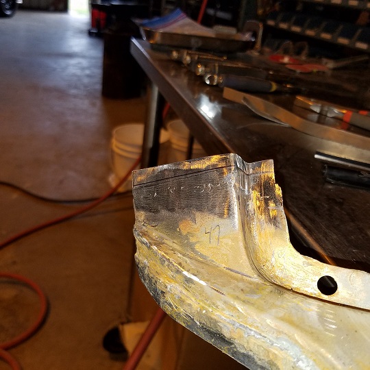 After a couple hours of taking the frame in and out about 10 times. Her she is fitted nice and tight. 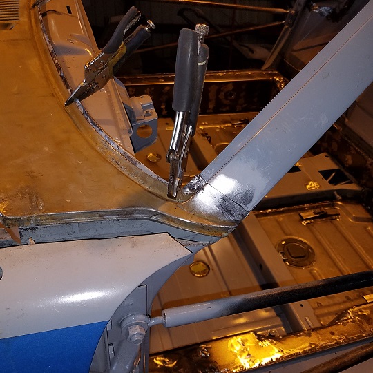 |
|
|
|
| cary |
Oct 19 2017, 09:02 AM
Post
#365
|
|
Advanced Member Group: Members Posts: 3,900 Joined: 26-January 04 From: Sherwood Oregon Member No.: 1,608 Region Association: Pacific Northwest |
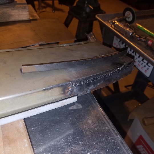
Then it was time to add the flange back on the cowl so it can be welded to the tub. It will be created in 2 pieces, the vertical and then the horizontal. This will take a little tinkering. This piece sets depth and the angle on the cowl.
Measurements down from the pressed out top roll on the cowl down to the plate. 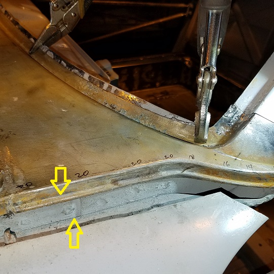 The work begins ............. 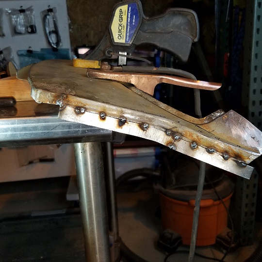 Fell asleep last night while writing this and watching the Blazer game |
|
|
|
| cary |
Oct 19 2017, 09:08 AM
Post
#366
|
|
Advanced Member Group: Members Posts: 3,900 Joined: 26-January 04 From: Sherwood Oregon Member No.: 1,608 Region Association: Pacific Northwest |
When time allows I'll try do a line drawing on how I'm putting this thing back together.
|
|
|
|
| mbseto |
Oct 19 2017, 04:09 PM
Post
#367
|
|
Senior Member Group: Members Posts: 1,257 Joined: 6-August 14 From: Cincy Member No.: 17,743 Region Association: North East States |
There are hardly any detailed threads on how the cowl is put together. This is great info.
|
|
|
|
| cary |
Oct 19 2017, 10:32 PM
Post
#368
|
|
Advanced Member Group: Members Posts: 3,900 Joined: 26-January 04 From: Sherwood Oregon Member No.: 1,608 Region Association: Pacific Northwest |
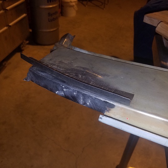
Today seemed like it was slow going. I think I reset the cowl 50 times before I tacked the first horizontal flange into place. The location of the flange sets the up and down orientation of the cowl.
 I also peeled back the fender a bit to give me a little more room to weld in the new inner fender support. This also gives you a better look at the two layers. Tomorrow I'll shoot some shots of how and where I'm measuring. Both front corners of the cowl were patched by Super In Law due to someone forgetting to latch the hood before they drove down the road. I started the day with adding back the end of the cowl that was ate by the tin worm and finish welding in the vertical flange. 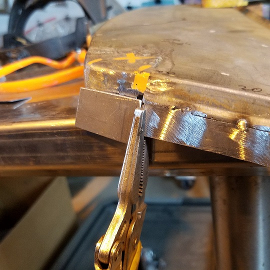 |
|
|
|
| cary |
Oct 20 2017, 10:21 PM
Post
#369
|
|
Advanced Member Group: Members Posts: 3,900 Joined: 26-January 04 From: Sherwood Oregon Member No.: 1,608 Region Association: Pacific Northwest |
While I'm working on the cowl repairs Super In Law is getting after the bumps and bruises in the frunk floor pan.
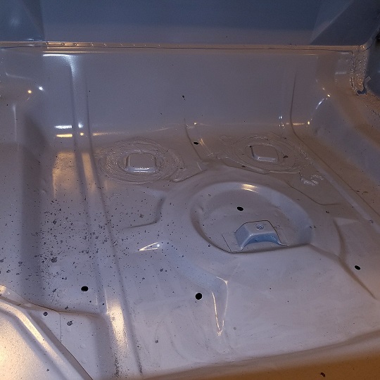 Two rails, some all thread and some steel blocks to pull the bumps down. 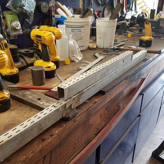 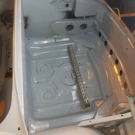 |
|
|
|
| cary |
Oct 21 2017, 08:36 AM
Post
#370
|
|
Advanced Member Group: Members Posts: 3,900 Joined: 26-January 04 From: Sherwood Oregon Member No.: 1,608 Region Association: Pacific Northwest |
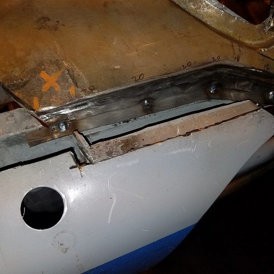
Before I attempt to weld in the cowl flange on the right I go ahead and set/hold the correct depth on the left with a self tapping screw.
 Having that done that I went ahead and got to right side all set and tacked on the flange. 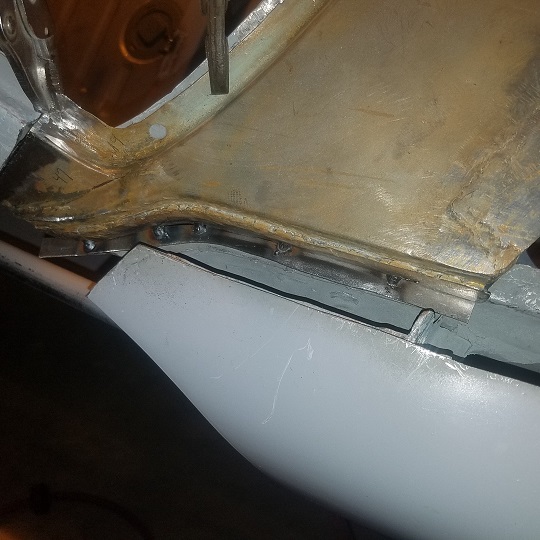 As I begin the vertical repairs on the cowl to hood channel I determine that I might need some more 20ga so I make a run to the Industrial Supply store here in Forest Grove and raid the scrap pile. Which is all you need for most of our repairs. On to the vertical portion of the what I'll call the cowl to hood channel. The big one at the top of the hood. Back to the workbench. I'll start with the right side. 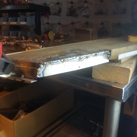 Slow going. Blip. Blip. Blip. Good solid steel all way across. 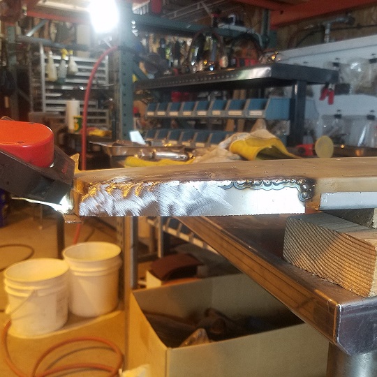 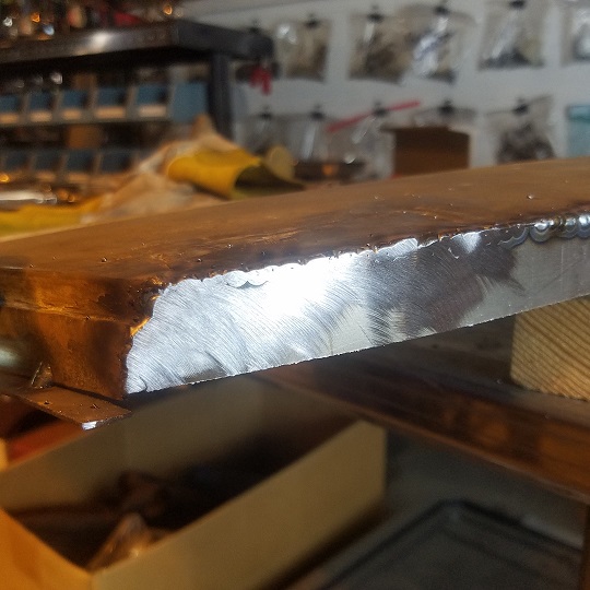 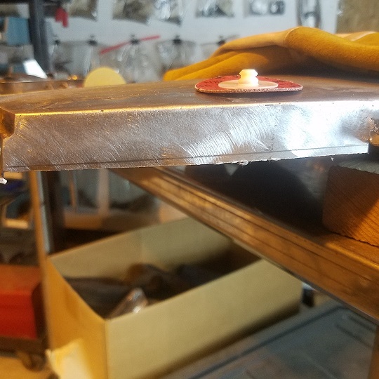 Tool Whore moment : Roloc Discs. I've progressed from Hf/Chinese to Norton and finally to 3m Cubitron II. This was done with 80gr on a Snap On 2 speed prep tool. Run at the low 6k speed as to not cut to fast. Bought both of mine on Ebay $50 and $70. The Cubritron cut the cleanest and the edge lasts the longest. Amazon. Last box of 50, $38 on sale. https://store.snapon.com/Micro-Sander-and-P...t--P648542.aspx Both Eastwood and TP Tools are making their own version now. The line on the bottom is my sanding line. I'll grind/sand up to that line for a starting point for the next right angle channel portion. 20mm down from the top. On to the left side. 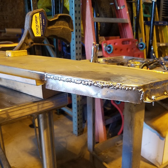 As you can see I ran into some bumpy stuff. I had about an inch of less that stellar steel. This is where Super In Law gets really frustrated. If you blow up a stitch. STOP. Cool yourself and the steel down. Then go back and try and put super small blips on the edge of the hole. Circle the hole. Then fill in the top, from the bottom up if you can. Hard to do. But it looks better after you sand/grind it down. End of the day ............. Typical work day at MiddleMotors is 10am till 5pm with an hour lunch away from the shop. I have to keep Super In Law fed and filled up. LOL. So we have a 6 hour work day. With me usually tinkering with shop stuff for an hour, so most work days are 5 hours. But until we get both Doug and Taylor's cars done, it will be 6 days per week. 3 at Rothsport and 3 at MiddleMotors. I hoping I can go play hooky from Rothsport another week. Gamroth will be heading to SEMA. He'll be in/on the 400R display. http://www.motortrend.com/news/guntherwerk...93-porsche-911/ http://www.motortrend.com/news/guntherwerk...93-porsche-911/ Rothsport 4.0 with over 400+ reliable long term horse power. Some day we'll build both a 1977 and a 2056 Rothsport MOTEC 914 Type 4. Wont be cheap if we use this as a starting point. https://type4store.com/engine-kits/2056-120-porsche-kit.html |
|
|
|
| bbrock |
Oct 21 2017, 03:56 PM
Post
#371
|
|
914 Guru Group: Members Posts: 5,269 Joined: 17-February 17 From: Montana Member No.: 20,845 Region Association: Rocky Mountains |
Thank you for all your welding and tool whore tips! They help me immensely.
When I blow through a patch of substandard steel, I'm finding I have better luck circling the hole with blips as you describe, then grinding the circle down a bit before filling it in. I think it just compensates for my lack of skill striking an arc at the bottom of the hole, but I'll take it. |
|
|
|
| raynekat |
Oct 21 2017, 09:14 PM
Post
#372
|
|
Advanced Member Group: Members Posts: 2,171 Joined: 30-December 14 From: Coeur d'Alene, Idaho Member No.: 18,263 Region Association: Pacific Northwest |
Piddle day for me, as you don't get much done with 5 month old twins in the house.
I finally assembled my speakers today. Since I'm using a vintage Becker stereo, it doesn't have much power. So I picked up a set of efficient Alpine 5.25" speakers to go into the 914 Rubber speaker housings I have. These are Alpine SPS-510 speakers. Not exactly "high fidelity" to the max, but should be sufficient for the few times I want to listen to some cruising tunes. I found the speaker grills on the internet and the 5.25" to 6.5" adapter rings on Ebay. I ended up using JB Weld for plastic (2 part epoxy) to glue the adapter ring into the backside of the speaker enclosure. Then just mounted the speaker and grill in from the front side using the holes that were predrilled in the adapter ring. Easy peasy. The majority of the time, I'll be listening to the 2.7 MFI RS engine winding out to seven grand plus I'll bet. (IMG:style_emoticons/default/w00t.gif) 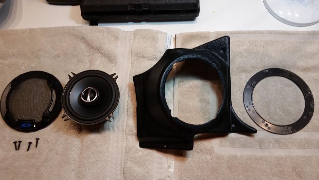 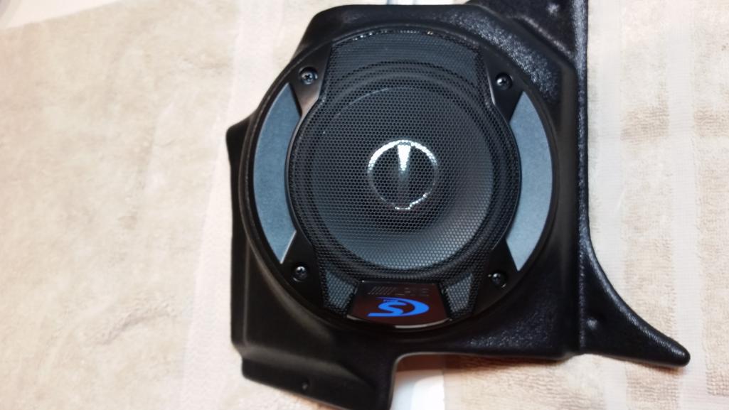 |
|
|
|
| raynekat |
Oct 21 2017, 09:20 PM
Post
#373
|
|
Advanced Member Group: Members Posts: 2,171 Joined: 30-December 14 From: Coeur d'Alene, Idaho Member No.: 18,263 Region Association: Pacific Northwest |
2nd micro job I got accomplished today was the installation of my torsion bars in the front suspension members.
These are Sway-A-Way hollow 21mm bars and they had been backordered through Elephant Racing for about 3 months time. Finally arrived at my home today. Since I'm still using the 914-4 front suspension, the spline count are different than what a 911 comes with....perhaps 914-6? The A-arms had been stripped and powdered coated. The adjuster caps had been given a black oxide coating. The bars slid in nicely; on went the foam sealing ring, and adjuster. Now all I need is a freshly painted car in which to install them. Coming.... 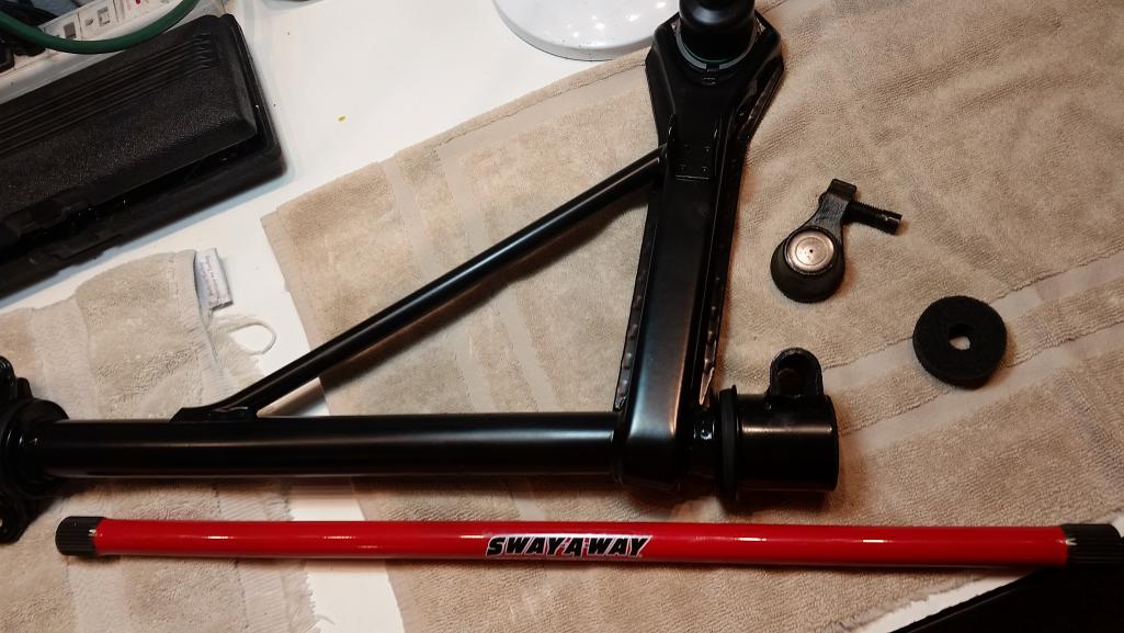 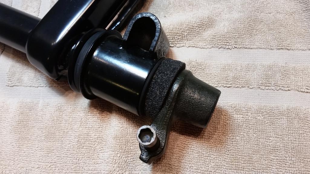 |
|
|
|
| cary |
Oct 21 2017, 11:18 PM
Post
#374
|
|
Advanced Member Group: Members Posts: 3,900 Joined: 26-January 04 From: Sherwood Oregon Member No.: 1,608 Region Association: Pacific Northwest |
While I was getting dirty under Mike's car. Super In Law was busy creating the channel for the cowl to hood area.
  |
|
|
|
| cary |
Oct 24 2017, 11:47 PM
Post
#375
|
|
Advanced Member Group: Members Posts: 3,900 Joined: 26-January 04 From: Sherwood Oregon Member No.: 1,608 Region Association: Pacific Northwest |
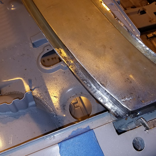
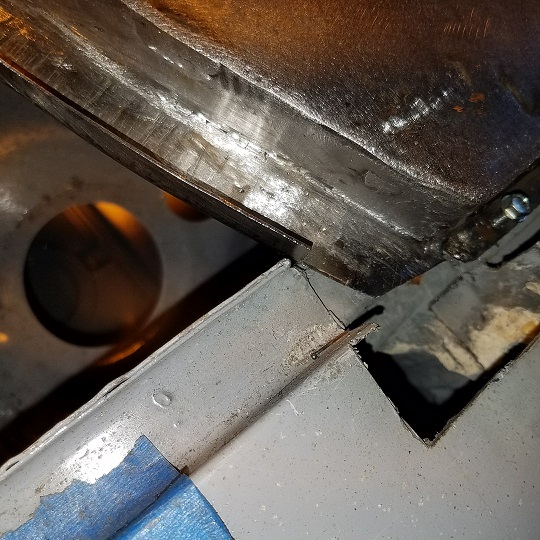
Tuesday 10/15/17
Taking off from Rothsport till 11/7 to get Doug's car finished. Jeff been good about it. He has Doug's engine and transmission projects going. Plus rally car number 3 is at the body shop getting a new roof. And the Desert Flyer is on my lift getting a few engineering enhancements. On we go to the cowl to hood channel recreations. 20ga and 20mm down from the flat cowl surface. A couple tacks to put it in the right place. 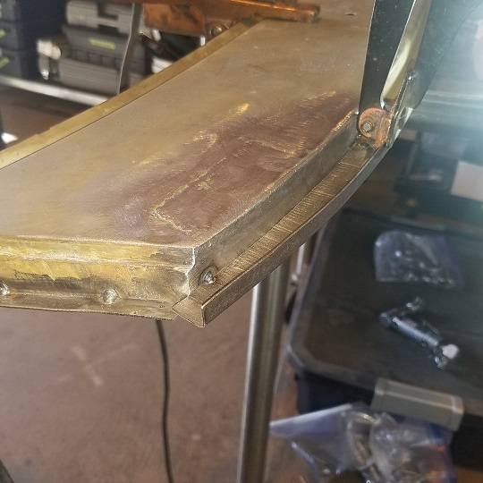 Part flipped over and the excess vertical portion sanded down to match the channel. 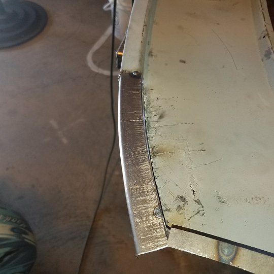 Weld penetrations from the back/bottom to the inside of the channel. 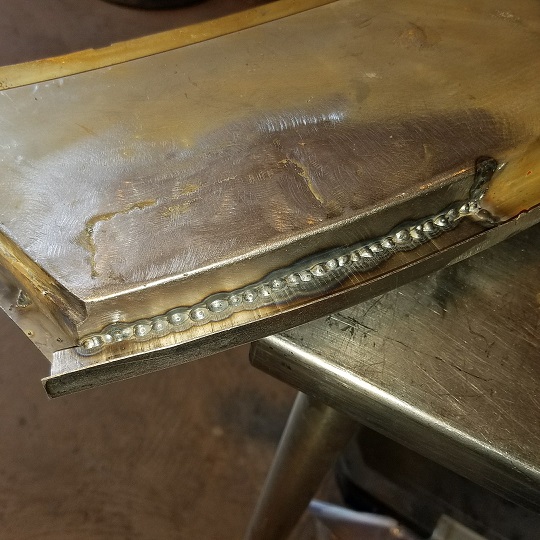 I use a thin cutting wheel to delicatley knock down the weld. Then a couple differnet RoLoc disks to finish. So in she went for a test fit. That was enough frustration for today. Prior to the test fit I did blow thru a couple three times while sanding/grinding the left side vertical portion that will be filled with the foam seal. Can't leave well enough alone. (IMG:style_emoticons/default/sad.gif) Now that my patience has been recharged it will get inspected for over sanding pin holes prior to giving the backside a re-treatment on cold galvanizing. 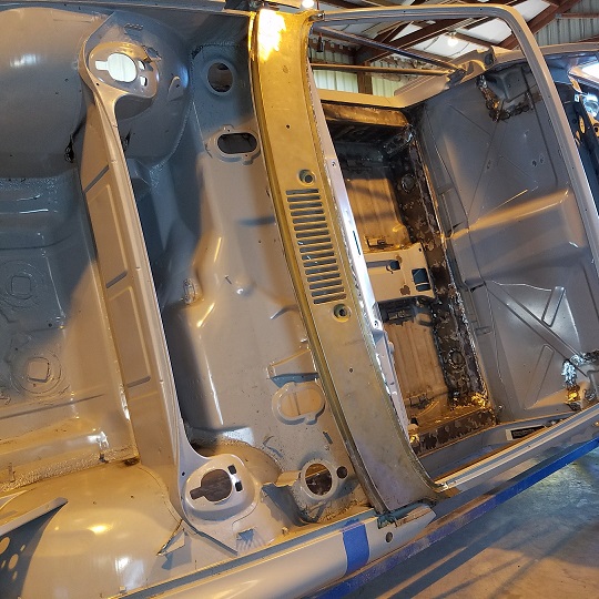 |
|
|
|
| mepstein |
Oct 25 2017, 04:54 AM
Post
#376
|
|
914-6 GT in waiting Group: Members Posts: 20,819 Joined: 19-September 09 From: Landenberg, PA/Wilmington, DE Member No.: 10,825 Region Association: MidAtlantic Region |
QUOTE(raynekat @ Oct 21 2017, 11:20 PM)  2nd micro job I got accomplished today was the installation of my torsion bars in the front suspension members. These are Sway-A-Way hollow 21mm bars and they had been backordered through Elephant Racing for about 3 months time. Finally arrived at my home today. Since I'm still using the 914-4 front suspension, the spline count are different than what a 911 comes with....perhaps 914-6? The A-arms had been stripped and powdered coated. The adjuster caps had been given a black oxide coating. The bars slid in nicely; on went the foam sealing ring, and adjuster. Now all I need is a freshly painted car in which to install them. 914-6 & 911 spline count are the same. Sounds like you got the proper 914-4 bars, just thicker than stock. |
|
|
|
| cary |
Oct 25 2017, 07:31 AM
Post
#377
|
|
Advanced Member Group: Members Posts: 3,900 Joined: 26-January 04 From: Sherwood Oregon Member No.: 1,608 Region Association: Pacific Northwest |
Back to checking things off the list.
Filled some screw holes in the engine compartment and on the fire wall. I'm beginning to use a paint stripper wheel for removing the epoxy. Works pretty good. 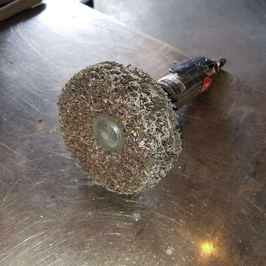 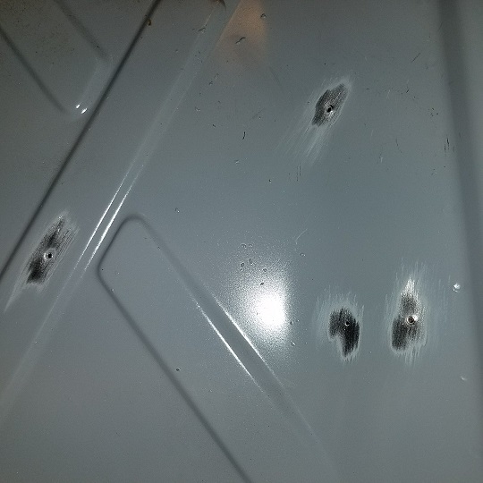 The spot weld cutter work on the MPS mount. 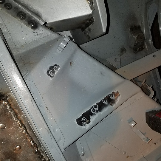 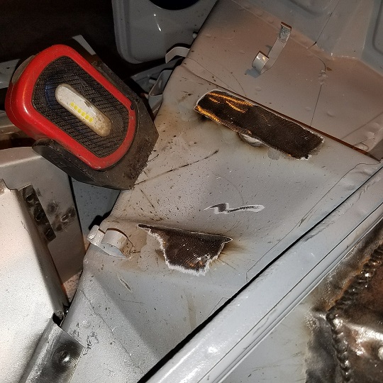 After all the discussion about Eastwood Internal Frame Coating. Here she is in action. Man that stuff is thin. The push button, tube and nozzle work really well. It will get a once over with the camera to make sure I have the coverage that I what. 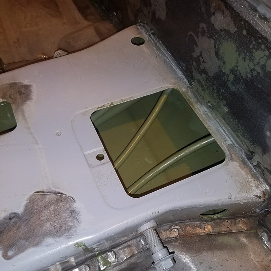 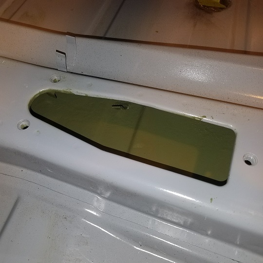 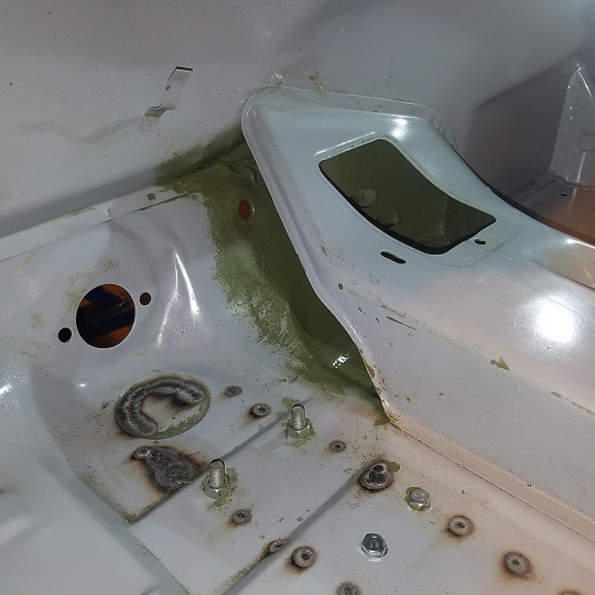 |
|
|
|
| cary |
Oct 25 2017, 08:53 AM
Post
#378
|
|
Advanced Member Group: Members Posts: 3,900 Joined: 26-January 04 From: Sherwood Oregon Member No.: 1,608 Region Association: Pacific Northwest |
I missed a couple shots of the left end all trimmed up.
  |
|
|
|
| cary |
Oct 25 2017, 04:29 PM
Post
#379
|
|
Advanced Member Group: Members Posts: 3,900 Joined: 26-January 04 From: Sherwood Oregon Member No.: 1,608 Region Association: Pacific Northwest |
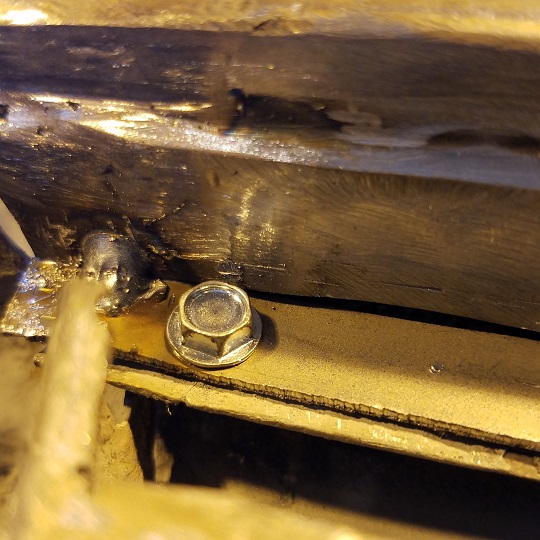
Did you want a matching set of harness hold downs on the bottom
side of the engine shelf for the MFI stuff? You were right, there were quite a few missing. 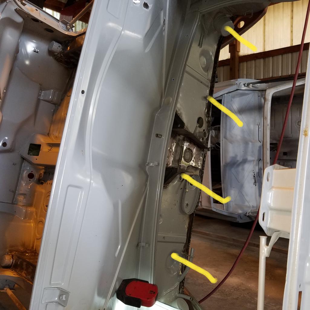 7 7 |
|
|
|
| raynekat |
Oct 25 2017, 04:43 PM
Post
#380
|
|
Advanced Member Group: Members Posts: 2,171 Joined: 30-December 14 From: Coeur d'Alene, Idaho Member No.: 18,263 Region Association: Pacific Northwest |
QUOTE(cary @ Oct 25 2017, 03:29 PM) Did you want a matching set of harness hold downs on the bottom side of the engine shelf for the MFI stuff? You were right, there were quite a few missing. 7Yes please. I'll be out on Friday bearing gifts. BTW....the big 63 today. Made it another year. (IMG:style_emoticons/default/biggrin.gif) |
|
|
|
|
2 User(s) are reading this topic (2 Guests and 0 Anonymous Users)
0 Members:

|
Lo-Fi Version | Time is now: 17th July 2026 - 10:49 PM |
Invision Power Board
v9.1.4 © 2026 IPS, Inc.