|
|
|
Porsche, and the Porsche crest are registered trademarks of Dr. Ing. h.c. F. Porsche AG.
This site is not affiliated with Porsche in any way. Its only purpose is to provide an online forum for car enthusiasts. All other trademarks are property of their respective owners. |
|
|


| 91422.7 |
 Mar 25 2015, 12:36 PM Mar 25 2015, 12:36 PM
Post
#1
|
|
Newbie  Group: Members Posts: 36 Joined: 8-October 14 From: Eugene, Oregon Member No.: 17,991 Region Association: Upper MidWest |
I'm in the process of installing a L-Jetronic Fuel Injection System on a 1975 Porsche 914 2.0L engine, which I'm installing the engine etc. in a 1970 914 body. The FI system was reportedly from a 1975 914 engine along with the engine. I'm needing some good photos or good diagrams that will help locate where all the wiring goes.
Items I've been working from: 1) Haynes 914 Owners Workshop Manual 2) Internet flow charts and electrical charts From the attached photos, you can see on the FI wiring harness I have several wires that are hanging loose. I believe the ones on the p/s the 4 wires together go to the MPC Sensor in the picture. Anyhow any help would be appreciated. From the picture you can see I have the wires going to the 4 injectors hooked up, not sure if they are going to the correct injector but I don't think it matters! When I purchased the 2.0L Engine it had twin carbs on it, it possibly had some parts removed. I think some of the wires go to the following items: 1) Cylinder head temp sensor 2) EGR Valve (which isn't going to be used on exhaust) 3) MPC Sensor (4 wire plug in) 4) Intake Manifold Temp Sensor 5) Thermostat Switch 6) Cold Start Valve 7) Engine Speed Relay 8) Throttle Valve Switch 9) Vacuum advance Disconnection 2-way valve 10) To starter terminal .....Maybe I've answered my own questions? (IMG:style_emoticons/default/driving.gif) Attached image(s) 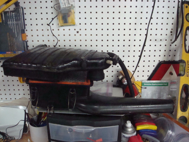 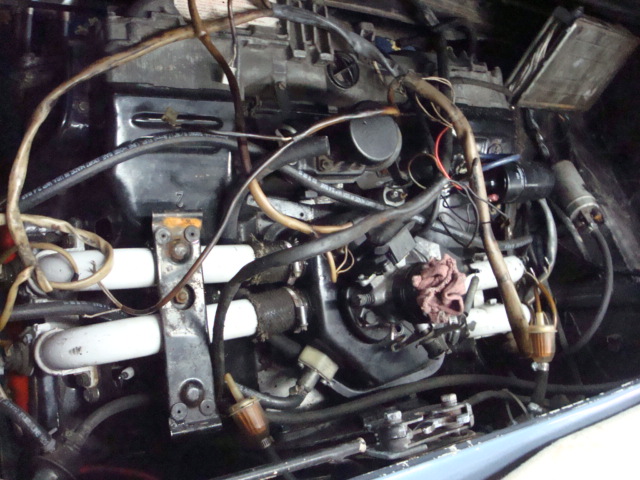 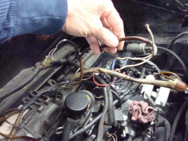 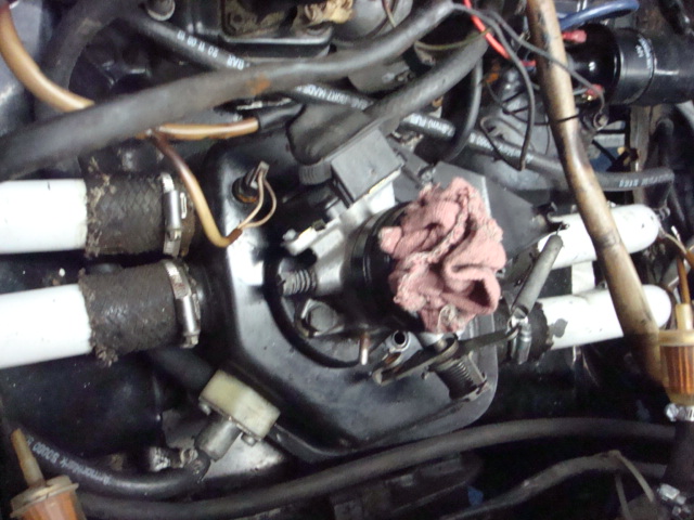 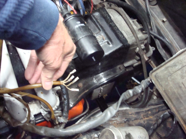 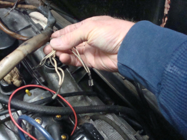 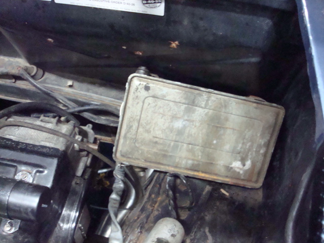 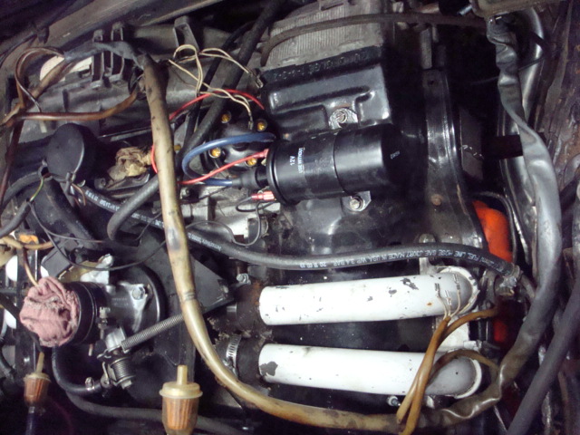 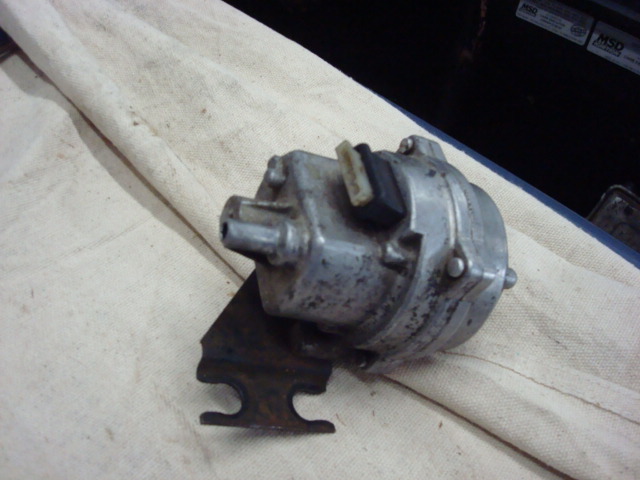 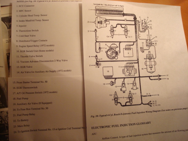 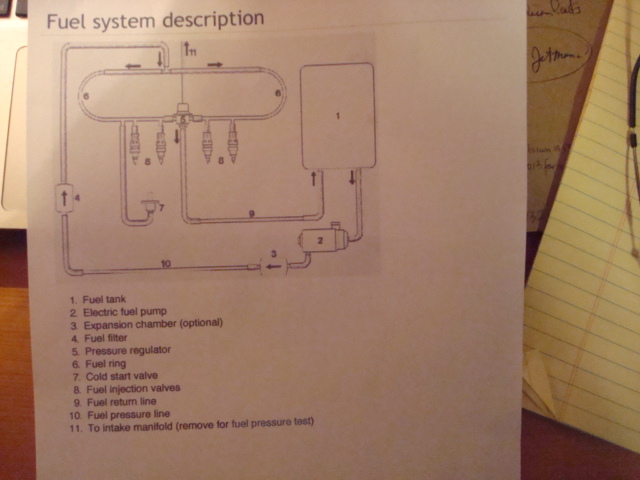
|
   |

 
|
  |
Replies(1 - 10)
| KELTY360 |
Mar 25 2015, 12:50 PM
Post
#2
|
|
914 Neferati Group: Members Posts: 5,031 Joined: 31-December 05 From: Pt. Townsend, WA Member No.: 5,344 Region Association: Pacific Northwest |
Looks like you have a D-jet system, not L-jet. D-jet would be correct for a '75 2.0L, L-jet was used on the 1.8.
|
|
|
|
| BeatNavy |
Mar 25 2015, 12:53 PM
Post
#3
|
|
Certified Professional Scapegoat Group: Members Posts: 2,924 Joined: 26-February 14 From: Easton, MD Member No.: 17,042 Region Association: MidAtlantic Region |
(IMG:style_emoticons/default/agree.gif) You will have better luck using D-Jet manuals / references. For example, L-Jet doesn't use the MPS you have there.
Very good reference: D-Jet Parts and Troubleshooting |
|
|
|
| montoya 73 2.0 |
Mar 25 2015, 12:54 PM
Post
#4
|
|
Lack of consideration to others, and Selfish! Group: Members Posts: 1,791 Joined: 27-October 04 From: Paso Robles, Ca. Member No.: 3,016 Region Association: Central California |
I don't know if this book will help but it's good to know;
Introduction....page 4 Chapter 1....Electricity and Electronics....page 5 Chapter 2....Emissions....page 26 Chapter 3....Tools....page31 Chapter 4....Tuning the Bosch-Injected Car....page 36 Chapter 5....The Lambda Sensor....page 42 Chapter 6....D-Jetronic Fuel Injection....page 44 Chapter 7....L-Jetronic System....page 64 Chapter 8....LH-Jetronic System....page 87 Chapter 9....K-Jetronic Fuel Injection....page 101 Chapter 10....K-Jetronic with Lambda....page 129 Chapter 11....KE-Jetronic System....page 148 Chapter 12....Motronic System....page 159 Chapter 13....The Asian Connection....page 162 Chapter 14....Fuel-Injection Performance Modifications....page 172 Index....page 175 CLICK HERE for "How to Tune and Modify Bosch Fuel Injection" |
|
|
|
| 91422.7 |
Mar 25 2015, 12:58 PM
Post
#5
|
|
Newbie Group: Members Posts: 36 Joined: 8-October 14 From: Eugene, Oregon Member No.: 17,991 Region Association: Upper MidWest |
Thanks for the update on the D-Jetronic identification....I will look into the reference book you mentioned! Thanks again
|
|
|
|
| JeffBowlsby |
Mar 25 2015, 01:25 PM
Post
#6
|
|
914 Wiring Harnesses Group: Members Posts: 8,485 Joined: 7-January 03 From: San Ramon CA Member No.: 104 Region Association: None |
See the FI wiring harness diagram on my wiring harness website
|
|
|
|
| Dave_Darling |
Mar 25 2015, 01:50 PM
Post
#7
|
|
914 Idiot Group: Members Posts: 14,981 Joined: 9-January 03 From: Silicon Valley / Kailua-Kona Member No.: 121 Region Association: Northern California |
General comments: Remove the plug for the FI wiring harness from the ECU. The pins in there are numbered from one end or the other. You can use a continuity tester to tell what the other end of the wire is connected to. Look up that number on the wiring diagram, and that's the component that the wire connects to.
First pic: 2-liter D-jet air cleaner. Second pic: Get rid of those low-pressure fuel filters; D-jet's 29 PSI will pop them and spray fuel on your engine. Not good. Third pic: Three wires cut off--could go to the trigger points down in the base of the distributor. If so, they would go into a 3-pin plastic plug body and have female spade terminals on the end. Fourth pic: Intake air temp and throttle position switches plugged in. Fifth pic: Four wires with 3mm female spades on the end. Very possibly the MPS connections. The should go into a four-connector plastic plug. Sixth pic: Three doubled wires with 6mm female spades. The grounds. They go onto a washer with three tabs sticking out that goes on one of the case through-bolts near the flywheel end of the top of the engine. Seventh pic: The ECU. Unplug it to check the circuit numbers for the wires you can't figure out. It should mount onto the front of the battery tray, unless the car was cut for A/C, in which case it would get mounted on the firewall. Eighth pic: Uhh, stuff. There's stuff in that picture... Ninth pic: MPS. Manifold Pressure Sensor. The bracket (should have two rubber grommets in those C-shaped cutouts) bolts to a bracket on the right side of the engine bay. Tenth and eleventh pics: Documentation. Good to have. More is also available here: http://bowlsby.net/914/Classic/TechNotebook.htm --DD |
|
|
|
| 91422.7 |
Mar 25 2015, 01:57 PM
Post
#8
|
|
Newbie Group: Members Posts: 36 Joined: 8-October 14 From: Eugene, Oregon Member No.: 17,991 Region Association: Upper MidWest |
QUOTE(Jeff Bowlsby @ Mar 25 2015, 12:25 PM)  See the FI wiring harness diagram on my wiring harness website Thank you Jeff, your website was helpful! Roy |
|
|
|
| 91422.7 |
Mar 25 2015, 01:59 PM
Post
#9
|
|
Newbie Group: Members Posts: 36 Joined: 8-October 14 From: Eugene, Oregon Member No.: 17,991 Region Association: Upper MidWest |
Dave, that helps a lot, I'm on it! (IMG:style_emoticons/default/driving.gif)
|
|
|
|
| Bleyseng |
Mar 26 2015, 08:03 AM
Post
#10
|
|
Aircooled Baby! Group: Members Posts: 13,034 Joined: 27-December 02 From: Seattle, Washington (for now) Member No.: 24 Region Association: Pacific Northwest |
Buy all the rubber boots for the plugs as without them the FI plugs will come off. Or send the FI harness to Jeff with all the pieces to be rebuilt.
What ECU do you have? look for the model numbers What MPS do you have? What injectors do you have? They need to match year wise. (IMG:style_emoticons/default/chair.gif) |
|
|
|
| 91422.7 |
Mar 26 2015, 03:33 PM
Post
#11
|
|
Newbie Group: Members Posts: 36 Joined: 8-October 14 From: Eugene, Oregon Member No.: 17,991 Region Association: Upper MidWest |
QUOTE(Bleyseng @ Mar 26 2015, 07:03 AM) Buy all the rubber boots for the plugs as without them the FI plugs will come off. Or send the FI harness to Jeff with all the pieces to be rebuilt. What ECU do you have? look for the model numbers What MPS do you have? What injectors do you have? They need to match year wise. (IMG:style_emoticons/default/chair.gif) Bleyseng; Thanks for the additional info about the FI plugs and I will have to check the numbers on the FI parts! |
|
|
|
|
1 User(s) are reading this topic (1 Guests and 0 Anonymous Users)
0 Members:

|
Lo-Fi Version | Time is now: 29th April 2024 - 12:57 PM |
Invision Power Board
v9.1.4 © 2024 IPS, Inc.