|
|
|
Porsche, and the Porsche crest are registered trademarks of Dr. Ing. h.c. F. Porsche AG.
This site is not affiliated with Porsche in any way. Its only purpose is to provide an online forum for car enthusiasts. All other trademarks are property of their respective owners. |
|
|


| peteyd |
 May 28 2015, 08:10 PM May 28 2015, 08:10 PM
Post
#1
|
|
Senior Member  Group: Members Posts: 743 Joined: 27-March 08 From: Elora, Ontario, Canada Member No.: 8,858 Region Association: Canada |
I had my car on the road for only two summers until I wanted to get a more reliable engine. I was not too familiar with the microsquirt, or megasquirt system, but when Mark started to offer a kit I knew that it would be a great starting point. I also had followed the progress of McMarks, rwilner and Zachs conversions and figured they had done enough trail blazing that it would be a piece of cake.
I started to piece together my own little manuel of pictures and notes from other threads and came up with my own little DIY powerpoint. So hopefully this thread can benefit others and hopefully these guys dont mind that I am reposting some of their photos. I didnt just decide to buy the system on a whim though. It all started one night when I was driving home on the highway and I heard a pretty large bang. I had just replaced my oil pressure relief valve with the new tangerine product and thought my engine had just exploded! I pulled over and realized after digging around that my #3 spark plug blew out of the threads. I have a head temp sensor under the plug, so Im thinking that it wasnt turned in all the way and the pressure was too great for the threads to hold the plug. BTW the pressure relief valve is a great product 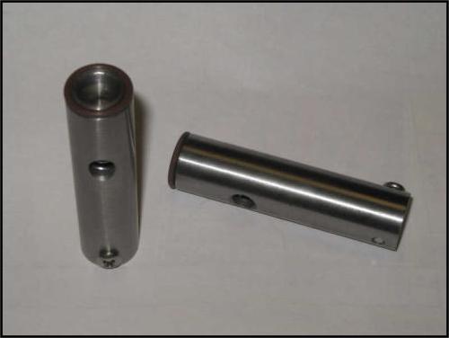 That winter I pulled the engine and then the head and put a time-sert in #3 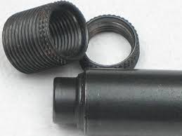 After bolting the heads back up, I noticed that my valve train geometry was off. So at that point I decided to measure and cut custom pushrods for the proper geometry. https://www.youtube.com/watch?v=aE-TJxlE7Ck And since I had the engine out, and Chris had just come out with another great engine product, I figured what the Hell, and bought his SS pushrod tubes and installed them. 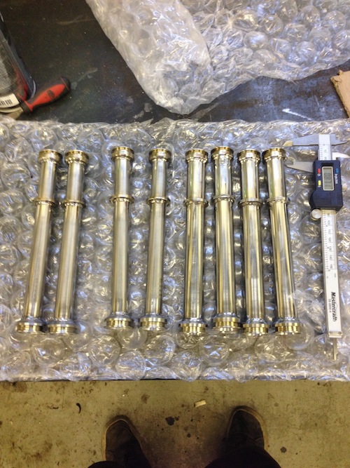 At this point I had been thinking about McMarks EFI kit seriously, and decided to pull the trigger. I ordered the kit from Mark @ Original Customs. I patiently waited and my kit finally came! Im using the stock 2L plenums and throttle body. Here is what came in the kit. (photos from Zach) I got the same stuff. 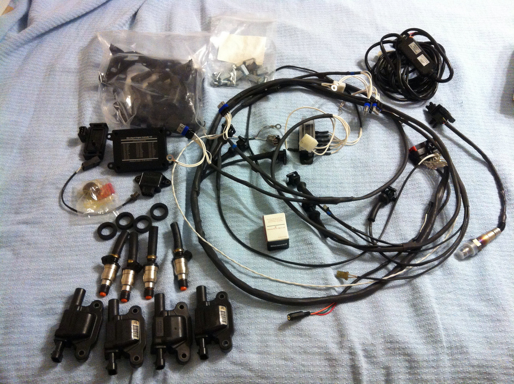 |
   |

 
|
Posts in this topic
peteyd 2056 microsquirt May 28 2015, 08:10 PM peteyd I started off by putting on the 36-1 trigger wheel... May 28 2015, 08:20 PM peteyd The next thing was pretty simple and cleaned up th... May 28 2015, 08:30 PM JmuRiz Ever thought of a /6 kit Mark :D May 28 2015, 08:40 PM
 McMark Glad to see you're getting started Pete. :thum... May 29 2015, 02:24 PM peteyd My next step was to start putting the plenums and ... May 28 2015, 08:45 PM porsche913b_sp Nice log, cant wait to see more, subscribed to you... May 28 2015, 08:45 PM peteyd Mark sent a brand new TPS sensor that needed to be... May 28 2015, 08:57 PM peteyd Plugging in some of the remaining wires was pretty... May 28 2015, 09:05 PM peteyd Thats all for tonight, and pretty much brings you ... May 28 2015, 09:27 PM altitude411 Fantastic write-up Pete. Very clean & nice w... May 28 2015, 09:38 PM Spoke Mark,
I looked on your website for this kit but d... May 29 2015, 02:38 PM JmuRiz I understand Mark...3.2 intakes are CRAZY money th... May 29 2015, 02:59 PM mepstein
I understand Mark...3.2 intakes are CRAZY money t... May 29 2015, 03:42 PM peteyd I got back to work on my car and was able to get q... Jun 16 2015, 01:26 PM peteyd After getting all the wiring and fuel lines hooked... Jun 16 2015, 02:06 PM ConeDodger Just heard my old 2432 Raby Kit motor that Mark an... Jun 16 2015, 10:28 PM falcor75 Just a thought, whats the pressure rating on that ... Jun 17 2015, 04:07 AM peteyd
Just heard my old 2432 Raby Kit motor that Mark a... Jun 17 2015, 06:07 AM Vacca Rabite Ahhh, you are about where I was last month now.
F... Jun 17 2015, 07:01 AM peteyd
Ahhh, you are about where I was last month now.
... Jun 17 2015, 07:43 AM aircooledtechguy Good write-up!! It's cool to watch yo... Jun 17 2015, 07:35 AM McMark Glad to see the progress Pete!
This sort of ... Jun 17 2015, 08:45 AM Vacca Rabite I have not touched it since Herb came over. I let... Jun 17 2015, 06:51 PM McMark
Literally every time I work on it now I think it... Jun 17 2015, 07:39 PM peteyd I got a little further along last night too. It tu... Jun 18 2015, 10:11 AM Vacca Rabite If you suspect firmware, follow the links in my th... Jun 18 2015, 11:05 AM McMark Even better. Teach a man to fish:
http://www.useas... Jun 18 2015, 11:06 AM aircooledtechguy One thing that I have found that will cause nothin... Jun 18 2015, 12:59 PM jd74914
For this reason, I add a simple terminal block an... Jun 18 2015, 01:54 PM McMark All sensor grounds go to the ECU. All non-sensor ... Jun 18 2015, 02:21 PM McMark Confirm this setting. Jun 18 2015, 03:06 PM peteyd
Confirm this setting.
I have done this step sev... Jun 18 2015, 07:47 PM McMark Microsquirt.com Jun 18 2015, 10:29 PM peteyd With the help of two buddies, I was able to put in... Jun 20 2015, 08:22 PM JamesM Been trying to avoid posting here as it is fun to ... Jun 21 2015, 12:19 AM peteyd
Been trying to avoid posting here as it is fun to... Jun 21 2015, 07:46 AM MrHyde Following this one Pete.. Can't wait to hear i... Jun 23 2015, 04:49 PM peteyd I have resorted to connecting with a desktop compu... Jul 8 2015, 09:00 AM McMark A few more months, and I'll just take a nice d... Jul 8 2015, 10:22 AM peteyd
A few more months, and I'll just take a nice ... Jul 8 2015, 10:27 AM McMark
A few more months, and I'll just take a nice... Jul 8 2015, 10:59 AM Michelj13 The project will be waiting for you when you are r... Jul 9 2015, 07:26 PM peteyd yipee! Im pumped now!
Last night my buddy... Aug 1 2015, 07:54 AM ConeDodger
yipee! Im pumped now!
Last night my budd... Aug 1 2015, 04:58 PM McMark Awesome!!! :boing: Aug 1 2015, 10:22 AM Ian Stott Hey Peter! Have been following this with great... Aug 2 2015, 05:30 AM peteyd
Hey Peter! Have been following this with grea... Aug 2 2015, 08:51 AM peteyd I have finally got my car running and driving... May 4 2018, 12:31 PM 913B
I have finally got my car running and driving... Aug 6 2021, 11:17 PM rudedude Pete, Any further updates? Would love to hear it... Oct 5 2018, 11:16 AM peteyd @rudedude
My car is running great! It fires ... Dec 28 2018, 11:29 AM rudedude Really glad to hear this. I have started to accum... Dec 29 2018, 09:44 AM Superhawk996 This is an awesome post. I'll bookmark for fu... Dec 29 2018, 10:07 PM VaccaRabite
This is an awesome post. I'll bookmark for f... Dec 30 2018, 08:42 AM peteyd @913B
In hind sight, the brass mounting plate wa... Aug 16 2021, 10:31 AM
McMark Glad to see you're getting started Pete. :thum... May 29 2015, 02:24 PM peteyd My next step was to start putting the plenums and ... May 28 2015, 08:45 PM porsche913b_sp Nice log, cant wait to see more, subscribed to you... May 28 2015, 08:45 PM peteyd Mark sent a brand new TPS sensor that needed to be... May 28 2015, 08:57 PM peteyd Plugging in some of the remaining wires was pretty... May 28 2015, 09:05 PM peteyd Thats all for tonight, and pretty much brings you ... May 28 2015, 09:27 PM altitude411 Fantastic write-up Pete. Very clean & nice w... May 28 2015, 09:38 PM Spoke Mark,
I looked on your website for this kit but d... May 29 2015, 02:38 PM JmuRiz I understand Mark...3.2 intakes are CRAZY money th... May 29 2015, 02:59 PM mepstein
I understand Mark...3.2 intakes are CRAZY money t... May 29 2015, 03:42 PM peteyd I got back to work on my car and was able to get q... Jun 16 2015, 01:26 PM peteyd After getting all the wiring and fuel lines hooked... Jun 16 2015, 02:06 PM ConeDodger Just heard my old 2432 Raby Kit motor that Mark an... Jun 16 2015, 10:28 PM falcor75 Just a thought, whats the pressure rating on that ... Jun 17 2015, 04:07 AM peteyd
Just heard my old 2432 Raby Kit motor that Mark a... Jun 17 2015, 06:07 AM Vacca Rabite Ahhh, you are about where I was last month now.
F... Jun 17 2015, 07:01 AM peteyd
Ahhh, you are about where I was last month now.
... Jun 17 2015, 07:43 AM aircooledtechguy Good write-up!! It's cool to watch yo... Jun 17 2015, 07:35 AM McMark Glad to see the progress Pete!
This sort of ... Jun 17 2015, 08:45 AM Vacca Rabite I have not touched it since Herb came over. I let... Jun 17 2015, 06:51 PM McMark
Literally every time I work on it now I think it... Jun 17 2015, 07:39 PM peteyd I got a little further along last night too. It tu... Jun 18 2015, 10:11 AM Vacca Rabite If you suspect firmware, follow the links in my th... Jun 18 2015, 11:05 AM McMark Even better. Teach a man to fish:
http://www.useas... Jun 18 2015, 11:06 AM aircooledtechguy One thing that I have found that will cause nothin... Jun 18 2015, 12:59 PM jd74914
For this reason, I add a simple terminal block an... Jun 18 2015, 01:54 PM McMark All sensor grounds go to the ECU. All non-sensor ... Jun 18 2015, 02:21 PM McMark Confirm this setting. Jun 18 2015, 03:06 PM peteyd
Confirm this setting.
I have done this step sev... Jun 18 2015, 07:47 PM McMark Microsquirt.com Jun 18 2015, 10:29 PM peteyd With the help of two buddies, I was able to put in... Jun 20 2015, 08:22 PM JamesM Been trying to avoid posting here as it is fun to ... Jun 21 2015, 12:19 AM peteyd
Been trying to avoid posting here as it is fun to... Jun 21 2015, 07:46 AM MrHyde Following this one Pete.. Can't wait to hear i... Jun 23 2015, 04:49 PM peteyd I have resorted to connecting with a desktop compu... Jul 8 2015, 09:00 AM McMark A few more months, and I'll just take a nice d... Jul 8 2015, 10:22 AM peteyd
A few more months, and I'll just take a nice ... Jul 8 2015, 10:27 AM McMark
A few more months, and I'll just take a nice... Jul 8 2015, 10:59 AM Michelj13 The project will be waiting for you when you are r... Jul 9 2015, 07:26 PM peteyd yipee! Im pumped now!
Last night my buddy... Aug 1 2015, 07:54 AM ConeDodger
yipee! Im pumped now!
Last night my budd... Aug 1 2015, 04:58 PM McMark Awesome!!! :boing: Aug 1 2015, 10:22 AM Ian Stott Hey Peter! Have been following this with great... Aug 2 2015, 05:30 AM peteyd
Hey Peter! Have been following this with grea... Aug 2 2015, 08:51 AM peteyd I have finally got my car running and driving... May 4 2018, 12:31 PM 913B
I have finally got my car running and driving... Aug 6 2021, 11:17 PM rudedude Pete, Any further updates? Would love to hear it... Oct 5 2018, 11:16 AM peteyd @rudedude
My car is running great! It fires ... Dec 28 2018, 11:29 AM rudedude Really glad to hear this. I have started to accum... Dec 29 2018, 09:44 AM Superhawk996 This is an awesome post. I'll bookmark for fu... Dec 29 2018, 10:07 PM VaccaRabite
This is an awesome post. I'll bookmark for f... Dec 30 2018, 08:42 AM peteyd @913B
In hind sight, the brass mounting plate wa... Aug 16 2021, 10:31 AM  |
1 User(s) are reading this topic (1 Guests and 0 Anonymous Users)
0 Members:

|
Lo-Fi Version | Time is now: 2nd April 2026 - 10:24 AM |
Invision Power Board
v9.1.4 © 2026 IPS, Inc.